EP0354861A1 - Vorrichtung, Anwendung und Verfahren zur Herstellung eines Regulators eines mit Schallgeschwindigkeit strömenden, sehr geringen Gasdurchflusses für die Gasadsorptions- und -Desorptionsmessung - Google Patents
Vorrichtung, Anwendung und Verfahren zur Herstellung eines Regulators eines mit Schallgeschwindigkeit strömenden, sehr geringen Gasdurchflusses für die Gasadsorptions- und -Desorptionsmessung Download PDFInfo
- Publication number
- EP0354861A1 EP0354861A1 EP89430022A EP89430022A EP0354861A1 EP 0354861 A1 EP0354861 A1 EP 0354861A1 EP 89430022 A EP89430022 A EP 89430022A EP 89430022 A EP89430022 A EP 89430022A EP 0354861 A1 EP0354861 A1 EP 0354861A1
- Authority
- EP
- European Patent Office
- Prior art keywords
- pressure
- tube
- gas
- flow rate
- regulator
- Prior art date
- Legal status (The legal status is an assumption and is not a legal conclusion. Google has not performed a legal analysis and makes no representation as to the accuracy of the status listed.)
- Granted
Links
Images
Classifications
-
- G—PHYSICS
- G05—CONTROLLING; REGULATING
- G05D—SYSTEMS FOR CONTROLLING OR REGULATING NON-ELECTRIC VARIABLES
- G05D7/00—Control of flow
- G05D7/01—Control of flow without auxiliary power
- G05D7/0186—Control of flow without auxiliary power without moving parts
-
- G—PHYSICS
- G01—MEASURING; TESTING
- G01N—INVESTIGATING OR ANALYSING MATERIALS BY DETERMINING THEIR CHEMICAL OR PHYSICAL PROPERTIES
- G01N15/00—Investigating characteristics of particles; Investigating permeability, pore-volume or surface-area of porous materials
- G01N15/08—Investigating permeability, pore-volume, or surface area of porous materials
- G01N15/0806—Details, e.g. sample holders, mounting samples for testing
-
- G—PHYSICS
- G01—MEASURING; TESTING
- G01N—INVESTIGATING OR ANALYSING MATERIALS BY DETERMINING THEIR CHEMICAL OR PHYSICAL PROPERTIES
- G01N15/00—Investigating characteristics of particles; Investigating permeability, pore-volume or surface-area of porous materials
- G01N15/08—Investigating permeability, pore-volume, or surface area of porous materials
- G01N15/088—Investigating volume, surface area, size or distribution of pores; Porosimetry
- G01N15/0893—Investigating volume, surface area, size or distribution of pores; Porosimetry by measuring weight or volume of sorbed fluid, e.g. B.E.T. method
Definitions
- the present invention relates to devices, applications and methods for manufacturing a regulator capable of ensuring very low sonic flow rate for gas adsorption and desorption measurements.
- the technical sector of the invention is that of the manufacture of gas volume measurement equipment.
- An application of the invention is the determination of the specific area of an adsorbent by the continuous introduction of adsorbable gas with very high precision.
- gas adsorption retention of gases at the surface
- porous or divided solids such as catalysts, adsorbents for purifying or separating gases or liquids, pigments, hydraulic binders, fillers for rubber or plastics, phytosanitary powders, etc.
- the gases used for these characterizations are sometimes chemisorbed (in particular H2, CO, NH3, O2 as well as various hydrocarbons) sometimes physisorbed (in particular N2, Ar, Kr, CO2, H2O).
- the quantification and exploitation of the adsorption phenomenon always involves the determination of more or less complete adsorption isotherms, that is to say the curves giving, at a given temperature, the quantity of gas adsorbed at equilibrium as a function of the pressure of this gas above the adsorbent; when the gas can give rise to three-dimensional condensation at the temperature of the experiment, the equilibrium pressure is usually expressed in relation to the saturated vapor pressure at this temperature and we speak of relative equilibrium pressure.
- the quantity of adsorbed gas is usually determined either by gas volumetry, or by gravimetry, or again by measuring variations in the concentration of the adsorbable gas in a carrier gas, using a catharometric detector. These three methods are usually used for a discontinuous determination of a limited number of points of the adsorption isotherm. It has long been sought to avoid the limitations of this discontinuous procedure (limitations in resolution and limitations in experimental convenience) by the use of a procedure of slow and continuous introduction of the adsorbable gas.
- the improvement in the measurements obtained encountered, up to the present invention the need to operate at adsorption flow rates of between 0.03 and 3 mm 3 (at normal temperature and pressure conditions: TPN) per second in order to to ensure satisfactory quasi-equilibrium conditions: it is indeed difficult to on the one hand to obtain such a flow, on the other hand to keep it stable for the duration of an experiment (between 15 min and 15 h) taking into account the variations of the atmospheric pressure and the increase in the pressure of almost balance during adsorption, and finally to be able to measure it.
- TPN normal temperature and pressure conditions
- adjustable high-precision leakage valves such as those used for calibrating mass spectometers, sintered metal powder filters, drawn capillary tubes (of glass or metal), laser drilled diaphragms with a diameter of the order of m.
- adjustable high-precision leakage valves such as those used for calibrating mass spectometers, sintered metal powder filters, drawn capillary tubes (of glass or metal), laser drilled diaphragms with a diameter of the order of m.
- the problem is to be able to produce a sonic gas flow regulator, allowing a flow as low and stable as 0.03 mm3 / sec, and remaining constant with an accuracy better than 1% for a fixed and constant upstream pressure, and a pressure downstream varying between vacuum and at least a tenth of the upstream pressure.
- a device comprising a regulator of low gas flow rate with a sonic flow rate usable in any known device for gas adsorption and desorption measurements, characterized in that it consists of a metal tube.
- ductile of small cross section, for example copper of which a small part of its length is crushed so that the internal wall of said tube is in contact with itself, which tube is mounted on a connection means ensuring on the one hand the seal around it, and on the other hand its mounting in said gas adsorption and desorption measuring device, so that it ensures the continuous supply of a very low gas flow rate in this device despite a variable back pressure therein between the vacuum and at least one tenth of the upstream supply pressure.
- a method of manufacturing a regulator of very low gas flow rate at sonic flow rate usable in any known device for gas adsorption and desorption measurements operating at given operating pressures and in which one wants to introduce a gas at a very low chosen flow rate characterized in that: - We take a ductile metal tube of small section, for example copper with a wall thickness sufficiently strong to support said differences in gas pressure of use; - Said tube is mounted on a connection means ensuring on the one hand the seal around it, and on the other hand its mounting in said device, which means is mounted near one end of said tube at sufficient distance to allow the following operation which can also be carried out beforehand; - Said tube is crushed over a short length between said flange and the corresponding end above; - Connect said connection means and said tube to any calibrated and known volumetric device, and send a gas at a given calibration pressure through one end of the tube and measure for example the pressure increase in the known volume where the other end opens and the initial pressure of which is chosen as
- the flow rate thus obtained is continuously determined and it is checked that it is constant and corresponds at most to the value chosen over the whole range of measurements of the desired downstream pressure variation and if this is not the case, continues the crushing operation by slightly increasing the nipping of the tube and the calibration is checked until the desired flow rate is obtained at the most, taking into account said operating pressures initially retained.
- the result is a new manufacturing process for a new sonic regulator that can provide very low flow rates for gas adsorption and desorption measurements.
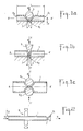
- FIG. 1a represents a section view of a tube 1 of ductile metal of small section, for example copper, but which can also be made of ductile steel, platinum, silver or gold, and of a length L such that these 2 ends 2.1 and 2.2 can be connected to a measuring device as described in figures 2 and 4.
- Said tube 1 is placed in a clamping means allowing it to be able to crush a small part of its length 1 so that the internal wall of the tube comes practically into contact with itself and can leave a free passage section 7 less than square micrometer.
- the latter is then crushed with the ball which is brought closer to anvil 4.1 by any clamping means 8 up to a distance d corresponding to the maximum sonic flow rate chosen, and following the calibration and the process already described above.
- This distance is a function of the thickness of said tube (ie at most equal to twice its thickness), operating pressures selected and the maximum flow required. If necessary, the deformed part is annealed between two tightening and calibration operations to stabilize the deformation obtained.
- FIG. 1b represents a sectional view of a second means of manufacturing, by crushing, of a flow regulator according to the invention: the tube 1 is in this example pinched between on one side a surface 4.2 forming an anvil and the other side a dihedral 5, which dihedral is brought closer to the surface 4.2 by any means 8 and as described in FIG. 1a.
- the surface 4.2 can be arbitrary it suffices that its intersection with the plane XX ′ passing through the edge of said dihedral and in which the displacement necessary for crushing takes place, is a convex line with radius of curvature greater than that of said tube 1.
- the advantage of using such a dihedral crushing means and that the length 1 thus pinched is small, or the smaller it is, the smaller the passage section 7 and the more the sonic operating range of the nozzle thus formed is broad.
- Figure 1c shows a sectional view of another means of manufacture, by crushing the tube 1 between on one side a roller 6.1, and on the other side a second roller 6.2; in fact, this second roller can be replaced by any surface making a stop and whose intersection with the plane YY ′ passing through the roller axis 6.1 and in which the displacement necessary for crushing takes place, is a convex line radius of curvature greater than that of said tube (1).
- Any clamping means 8 allows the rollers 6.1 and 6.2 to be brought together and the calibration manufacturing method already described previously is applied as in FIGS. 1a and 1b.
- the three crushing means above are not limiting and are cited by way of example: it is indeed possible to crush the tube also either by an annular constriction created by hydraulic pressure or the circular displacement of a roller either by several geometric shapes, such as 4 cylinders parallel to the axis of said tube.
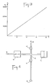
- FIG. 2 represents a regulator assembly produced for example according to one of the methods described in FIGS. 1a, 1b, 1c, which regulator consists of the tube 1 of which a part 7 is crushed to constitute the sonic flow nozzle and all connection means 9 for example an ultra-high vacuum flange with metal seals.
- This flange 9 ensures on the one hand the tightness around the tube 1 and on the other hand allows the assembly of the assembly on any measurement circuit as described in FIG. 4; this flange can be mounted prior to the clamping operation on the tube and at a sufficient distance from the end 2.1 to allow said clamping and crushing operation.
- the other end 2.2 is connected to a supply of pressurized gas 10 to be sent at constant flow rate into the enclosure 11 where the pressure and adsorption volume measurements are made.
- FIG. 3 shows an example of a pressure curve obtained by mounting a flow regulator as described and produced according to the method of the present invention on a continuous volumetric apparatus allowing adsorption desorption measurements.
- the pressure P10 upstream of supplying a regulator with nitrogen and for the use selected for this test is 350,000 pascals and the volume of the enclosure 11 closed in which the vacuum was previously produced and then in which is sent the gas flow rate according to the description of Figure 2 is 25 cm3: the curve of Figure 3 then gives the pressure increase P11 as a function of time T expressed in hours; this is perfectly regular, therefore proving that the flow rate is indeed constant and stable; this is 0.25 mm3 / sec and in fact remains constant at 0.5% close to the maximum variation for the upstream pressure P10 retained for use of 350,000 Pa and for a downstream pressure P11 varying from 0 to 30,000 Pa.
- FIG. 4 represents a diagram of assembly of a sonic regulator in a known measuring device for gas desorption adsorption that is as simple as one can imagine.
- This device comprises in a known manner: - a vial 12 containing a sample of the adsorbent material and maintained at the desired temperature (by example 77 K for nitrogen adsorption for a specific area determination by the BET method (Brunauer-Emmett-Teller) known as written in the recommendations of the IUPAC (Union Internale de Chimie Pure and Applied) for the presentation of gas adsorption data.
- An absolute pressure sensor 13 allowing continuous recording of the quasi-equilibrium pressure.
- a regulator 14 supplied with adsorbable gas under constant pressure 10.
- This pressure should, in theory at least equal (and, in practice, higher) to the quotient of the maximum downstream pressure by the "critical ratio" corresponding to the transition from sub regime -sonic at the sonic flow regime for the gas considered.
- Said regulator 14 or constant flow meter is a regulator such as for example that described in FIG. 2 and to ensure a chosen maximum flow comprised between 0.25 and 25 mm 3 / sec, constant at 1% near maximum variation for a pressure downstream in said apparatus or device varying from 0 to 100,000 Pa. - a reference volume 15 (or device volume) of constant value and limited by the regulator 14, the pressure sensor 13 and the valves 16 and 17.
- the plotting of an adsorption isotherm is as follows: - At the start, the bulb 12 containing the adsorbent is under vacuum and the valve 16 is closed. - The valve 17 (towards the vacuum 18) is open and creates in the reference volume 15 a dynamic vacuum with an initial residual pressure Pi resulting from a balance between the flow of gas entering through the regulator 14 (the pressure upstream of the latter being kept constant by a suitable pressure regulator) and the gas flow pumped through the valve 17. - This pressure Pi is measured, as well as the temperature at which the volume 15 is maintained and the amount of initial gas present in this volume is deduced therefrom. - The pressure signal as a function of time is recorded on a graphic recorder or in the memory of a microcomputer.
- An interesting application of the device described in FIG. 4 is the rapid measurement of specific area by the BET method with nitrogen which uses the known method known as "at 1 point". Instead of determining the 3 to 5 points of the adsorption isotherm generally recommended for the application of the method, only one point of the isotherm is determined for a chosen equilibrium pressure. a priori in the vicinity of one third of the saturated vapor pressure of nitrogen (itself close to 100,000 Pa at the usual temperature of adsorption). By making the double assumption that the adsorption energy is high on the first layer and that the BET equation applies correctly on all this first part of the isotherm (of which we only know one point) we end up with a value of the specific area.
- This value can differ by several tens of% from that which is calculated using several points of the adsorption isotherm, especially when it turns out that the BET equation only applies to a limited portion of the isotherm or when the adsorption energy is not much higher on the first layer than on the following (as is the case for nitrogen adsorption on organic polymers or for the adsorption of argon - also usable for the BET method - on very many).
- the device according to the invention allows the following procedure:
- the adsorbable gas is introduced at a constant but relatively rapid speed until the pressure for forming the monolayer is reached as it has was determined in the previous paragraph.
- the introduction is stopped and waiting for the desired balance to be obtained, characterized by a predetermined value of the slope of the recording of the pressure as a function of time. Ideally, this slope should be chosen to be zero, but the time requirements lead to assigning it a finite value (for example: variation of the pressure read less than 1/1000 of its value over 30 seconds).
- the quantity then adsorbed is most often not discernible from that which would be adsorbed for a perfect balance, itself difficult to achieve in all rigor since it supposes the total overpressure of any temperature fluctuation of the volumetric apparatus ( whatever it is), any fluctuation in the level of the cryogenic bath making it possible to maintain the temperature of the adsorbent and any variation in atmospheric pressure capable of modifying the boiling temperature of the latter.
- the quantity adsorbed at this instant is determined, the final equilibrium pressure necessarily being a little lower than the exact pressure for forming the monolayer.
- the duration of the routine experiment may typically be, after cooling of the adsorbent, from 5 to 10 minutes to obtain the final adsorption equilibrium, ie a duration of the order of 1/4 d time, as expected from a quick routine measurement.
- Another interesting use of the regulating device according to the invention relates to gas desorption measures.
- the operation of the flow rate regulator at sonic flow speed according to the invention is different for a desorption experiment, itself necessary, mainly in the case of nitrogen, for the evaluation of the size distribution of the mesopores ( pore opening between 2 and 50 nm). These pores play an important role in most adsorbents of technological interest (excluding molecular sieves, all of whose pores, less than 2 nm, can then be studied from the single adsorption branch of the isothermal).
- the size of the mesopores is deduced from the relation (based on Kelvin's law) which links the pressure at which a given category of pores empties (in desorption) with the radius of curvature of the liquid meniscus located at the opening of these pores (provided that they have previously been saturated with adsorbable by capillary condensation).
Landscapes
- Chemical & Material Sciences (AREA)
- General Physics & Mathematics (AREA)
- Physics & Mathematics (AREA)
- Biochemistry (AREA)
- Dispersion Chemistry (AREA)
- Health & Medical Sciences (AREA)
- Life Sciences & Earth Sciences (AREA)
- Analytical Chemistry (AREA)
- General Health & Medical Sciences (AREA)
- Immunology (AREA)
- Pathology (AREA)
- Automation & Control Theory (AREA)
- Engineering & Computer Science (AREA)
- Measuring Volume Flow (AREA)
- Separation Of Gases By Adsorption (AREA)
Applications Claiming Priority (2)
| Application Number | Priority Date | Filing Date | Title |
|---|---|---|---|
| FR8810972 | 1988-08-12 | ||
| FR8810972A FR2635383B1 (fr) | 1988-08-12 | 1988-08-12 | Dispositif, application et procede de fabrication d'un regulateur de tres faible debit gazeux a vitesse d'ecoulement sonique pour les mesures d'adsorption et de desorption gazeuse |
Publications (2)
| Publication Number | Publication Date |
|---|---|
| EP0354861A1 true EP0354861A1 (de) | 1990-02-14 |
| EP0354861B1 EP0354861B1 (de) | 1992-05-20 |
Family
ID=9369380
Family Applications (1)
| Application Number | Title | Priority Date | Filing Date |
|---|---|---|---|
| EP89430022A Expired - Lifetime EP0354861B1 (de) | 1988-08-12 | 1989-08-10 | Vorrichtung, Anwendung und Verfahren zur Herstellung eines Regulators eines mit Schallgeschwindigkeit strömenden, sehr geringen Gasdurchflusses für die Gasadsorptions- und -Desorptionsmessung |
Country Status (6)
| Country | Link |
|---|---|
| US (1) | US4967591A (de) |
| EP (1) | EP0354861B1 (de) |
| JP (1) | JPH0288963A (de) |
| DE (1) | DE68901593D1 (de) |
| ES (1) | ES2031703T3 (de) |
| FR (1) | FR2635383B1 (de) |
Cited By (1)
| Publication number | Priority date | Publication date | Assignee | Title |
|---|---|---|---|---|
| CN106092820A (zh) * | 2016-06-24 | 2016-11-09 | 中国石油天然气股份有限公司 | 一种基于密度的泥页岩气体吸附气量校正方法及装置 |
Families Citing this family (4)
| Publication number | Priority date | Publication date | Assignee | Title |
|---|---|---|---|---|
| US5342580A (en) * | 1990-04-17 | 1994-08-30 | Alan Brenner | Apparatus and method for measuring the amount of gas adsorbed on or desorbed from a solid and reactions of a gas with a solid |
| JP3580645B2 (ja) * | 1996-08-12 | 2004-10-27 | 忠弘 大見 | 圧力式流量制御装置 |
| JP5991834B2 (ja) * | 2012-03-26 | 2016-09-14 | アズビルTaco株式会社 | 極微細絞り機構と極微細絞り部の形成方法 |
| EP2672247B1 (de) * | 2012-06-05 | 2018-04-04 | Sciemetric Instruments Inc. | Leckprüfungsverfahren und -systeme |
Citations (5)
| Publication number | Priority date | Publication date | Assignee | Title |
|---|---|---|---|---|
| US2664111A (en) * | 1949-01-19 | 1953-12-29 | Sinclair Res Lab Inc | Fluid flow control |
| US3139747A (en) * | 1961-07-03 | 1964-07-07 | Continental Oil Co | Flow regulator |
| US3211007A (en) * | 1963-03-29 | 1965-10-12 | Cabot Corp | Measurement of surface areas of solids |
| FR1515676A (fr) * | 1967-03-28 | 1968-03-01 | Siemens Ag | Dispositif pour régler et maintenir constant le débit massique des gaz |
| US4489593A (en) * | 1982-09-09 | 1984-12-25 | Omicron Technology Corporation | Method and apparatus for determining the amount of gas adsorbed or desorbed from a solid |
Family Cites Families (4)
| Publication number | Priority date | Publication date | Assignee | Title |
|---|---|---|---|---|
| US2729969A (en) * | 1951-04-26 | 1956-01-10 | American Cyanamid Co | Method for automatic measurement of surface area and pore volume |
| US3255122A (en) * | 1962-01-02 | 1966-06-07 | Chevron Res | Control of surface area in a catalyst manufacturing process |
| FR2080194A5 (de) * | 1970-02-26 | 1971-11-12 | Commissariat Energie Atomique | |
| JPS61102538A (ja) * | 1984-10-23 | 1986-05-21 | オミクロン・テクノロジ−・コ−ポレイシヨン | 固体により吸着または固体から脱着される気体の量を決定するための方法および装置 |
-
1988
- 1988-08-12 FR FR8810972A patent/FR2635383B1/fr not_active Expired - Lifetime
-
1989
- 1989-08-07 US US07/390,212 patent/US4967591A/en not_active Expired - Fee Related
- 1989-08-10 ES ES198989430022T patent/ES2031703T3/es not_active Expired - Lifetime
- 1989-08-10 EP EP89430022A patent/EP0354861B1/de not_active Expired - Lifetime
- 1989-08-10 DE DE8989430022T patent/DE68901593D1/de not_active Expired - Lifetime
- 1989-08-11 JP JP1207072A patent/JPH0288963A/ja active Pending
Patent Citations (5)
| Publication number | Priority date | Publication date | Assignee | Title |
|---|---|---|---|---|
| US2664111A (en) * | 1949-01-19 | 1953-12-29 | Sinclair Res Lab Inc | Fluid flow control |
| US3139747A (en) * | 1961-07-03 | 1964-07-07 | Continental Oil Co | Flow regulator |
| US3211007A (en) * | 1963-03-29 | 1965-10-12 | Cabot Corp | Measurement of surface areas of solids |
| FR1515676A (fr) * | 1967-03-28 | 1968-03-01 | Siemens Ag | Dispositif pour régler et maintenir constant le débit massique des gaz |
| US4489593A (en) * | 1982-09-09 | 1984-12-25 | Omicron Technology Corporation | Method and apparatus for determining the amount of gas adsorbed or desorbed from a solid |
Cited By (2)
| Publication number | Priority date | Publication date | Assignee | Title |
|---|---|---|---|---|
| CN106092820A (zh) * | 2016-06-24 | 2016-11-09 | 中国石油天然气股份有限公司 | 一种基于密度的泥页岩气体吸附气量校正方法及装置 |
| CN106092820B (zh) * | 2016-06-24 | 2019-03-15 | 中国石油天然气股份有限公司 | 一种基于密度的泥页岩气体吸附气量校正方法及装置 |
Also Published As
| Publication number | Publication date |
|---|---|
| FR2635383B1 (fr) | 1990-11-23 |
| FR2635383A1 (fr) | 1990-02-16 |
| EP0354861B1 (de) | 1992-05-20 |
| JPH0288963A (ja) | 1990-03-29 |
| ES2031703T3 (es) | 1992-12-16 |
| US4967591A (en) | 1990-11-06 |
| DE68901593D1 (de) | 1992-06-25 |
Similar Documents
| Publication | Publication Date | Title |
|---|---|---|
| EP1336843B1 (de) | Schutz eines chromatographischen Bettes in Chromatographievorrichtungen mit dynamischer axialer Kompression | |
| CA2838187C (fr) | Dispositif et procede de test d'un echantillon, en particulier de discrimination d'un gaz d'un echantillon | |
| EP0354861B1 (de) | Vorrichtung, Anwendung und Verfahren zur Herstellung eines Regulators eines mit Schallgeschwindigkeit strömenden, sehr geringen Gasdurchflusses für die Gasadsorptions- und -Desorptionsmessung | |
| FR3047067B1 (fr) | Systeme de mesure de debit d'un liquide et son utilisation | |
| WO2001098751A1 (fr) | Procede pour determiner l'energie de surface d'un solide finement divise | |
| FR2791434A1 (fr) | Procede et dispositif d'analyse thermodynamique d'un melange de fluides | |
| FR2683043A1 (fr) | Dispositif et procede de mesure integrale et continue d'adsorption et de desorption gazeuse. | |
| FR2583876A1 (fr) | Procede et dispositif de mesure des caracteristiques de cisaillement d'un sol | |
| EP3405762B1 (de) | Fluiddrucksensor und verwendung davon | |
| EP1036313A1 (de) | Verfahren und vorrichtung zur untersuchung der auswirkung einer superkritischen flüssigkeit auf den übergang der einen in die andere von zwei kondensierten phasen eines materials und deren anwendung für ein polymer | |
| EP2456562B1 (de) | Aerodynamischer zerhacker zum pulsieren einer gasströmung | |
| FR2546301A1 (fr) | Methode et appareil de mesure dynamique des aires massiques (surfaces specifiques) et de determination d'isothermes par adsorption et desorption d'un melange gazeux de composition constante | |
| CA2835021A1 (fr) | Procede de mesure de la viscosite d'un fluide et viscosimetre | |
| EP1336831B1 (de) | Vorrichtung zum Messen der Leckmenge einer abgedichteten Anordnung | |
| FR2686696A1 (fr) | Procede de determination de la permeabilite a l'eau liquide d'un materiau poreux non sature d'eau et appareil pour sa mise en óoeuvre. | |
| CN116559030B (zh) | 一种多孔薄膜表界面张力的测量方法 | |
| FR2653884A1 (fr) | Procede et dispositif de caracterisation de la texture d'un materiau poreux. | |
| CN101539513B (zh) | 塑料油箱表层氟化效果的检测方法 | |
| FR2830939A1 (fr) | Dispositif et procede de mesure et/ou detection d'un taux et debit de gaz dans l'haleine | |
| FR2688826A1 (fr) | Procede et dispositif de prelevement d'un echantillon de fluide. | |
| FR2971844A1 (fr) | Dispositif pour determiner la qualite de l'etancheite d'un caisson | |
| FR2568373A1 (fr) | Permeametre | |
| FR2487067A1 (fr) | Appareil pour la mesure des debits de fluide, particulierement de gaz sous pression | |
| FR2736717A1 (fr) | Procede de controle d'un debit de fuite et application du procede a la mesure du taux de gaz dans un liquide | |
| BE568201A (de) |
Legal Events
| Date | Code | Title | Description |
|---|---|---|---|
| PUAI | Public reference made under article 153(3) epc to a published international application that has entered the european phase |
Free format text: ORIGINAL CODE: 0009012 |
|
| AK | Designated contracting states |
Kind code of ref document: A1 Designated state(s): BE CH DE ES GB IT LI NL |
|
| 17P | Request for examination filed |
Effective date: 19900417 |
|
| 17Q | First examination report despatched |
Effective date: 19910612 |
|
| GRAA | (expected) grant |
Free format text: ORIGINAL CODE: 0009210 |
|
| AK | Designated contracting states |
Kind code of ref document: B1 Designated state(s): BE CH DE ES GB IT LI NL |
|
| REF | Corresponds to: |
Ref document number: 68901593 Country of ref document: DE Date of ref document: 19920625 |
|
| ITF | It: translation for a ep patent filed | ||
| GBT | Gb: translation of ep patent filed (gb section 77(6)(a)/1977) | ||
| REG | Reference to a national code |
Ref country code: ES Ref legal event code: FG2A Ref document number: 2031703 Country of ref document: ES Kind code of ref document: T3 |
|
| PLBE | No opposition filed within time limit |
Free format text: ORIGINAL CODE: 0009261 |
|
| STAA | Information on the status of an ep patent application or granted ep patent |
Free format text: STATUS: NO OPPOSITION FILED WITHIN TIME LIMIT |
|
| 26N | No opposition filed | ||
| PGFP | Annual fee paid to national office [announced via postgrant information from national office to epo] |
Ref country code: NL Payment date: 19950725 Year of fee payment: 7 |
|
| PGFP | Annual fee paid to national office [announced via postgrant information from national office to epo] |
Ref country code: ES Payment date: 19950802 Year of fee payment: 7 |
|
| PGFP | Annual fee paid to national office [announced via postgrant information from national office to epo] |
Ref country code: GB Payment date: 19950804 Year of fee payment: 7 |
|
| PGFP | Annual fee paid to national office [announced via postgrant information from national office to epo] |
Ref country code: CH Payment date: 19950816 Year of fee payment: 7 |
|
| PGFP | Annual fee paid to national office [announced via postgrant information from national office to epo] |
Ref country code: DE Payment date: 19950821 Year of fee payment: 7 |
|
| PGFP | Annual fee paid to national office [announced via postgrant information from national office to epo] |
Ref country code: BE Payment date: 19950906 Year of fee payment: 7 |
|
| PG25 | Lapsed in a contracting state [announced via postgrant information from national office to epo] |
Ref country code: GB Effective date: 19960810 |
|
| PG25 | Lapsed in a contracting state [announced via postgrant information from national office to epo] |
Ref country code: ES Free format text: LAPSE BECAUSE OF EXPIRATION OF PROTECTION Effective date: 19960812 |
|
| PG25 | Lapsed in a contracting state [announced via postgrant information from national office to epo] |
Ref country code: LI Effective date: 19960831 Ref country code: CH Effective date: 19960831 Ref country code: BE Effective date: 19960831 |
|
| BERE | Be: lapsed |
Owner name: CENTRE NATIONAL DE LA RECHERCHE SCIENTIFIQUE CNRS Effective date: 19960831 |
|
| PG25 | Lapsed in a contracting state [announced via postgrant information from national office to epo] |
Ref country code: NL Effective date: 19970301 |
|
| GBPC | Gb: european patent ceased through non-payment of renewal fee |
Effective date: 19960810 |
|
| REG | Reference to a national code |
Ref country code: CH Ref legal event code: PL |
|
| NLV4 | Nl: lapsed or anulled due to non-payment of the annual fee |
Effective date: 19970301 |
|
| PG25 | Lapsed in a contracting state [announced via postgrant information from national office to epo] |
Ref country code: DE Effective date: 19970501 |
|
| REG | Reference to a national code |
Ref country code: ES Ref legal event code: FD2A Effective date: 19990601 |
|
| PG25 | Lapsed in a contracting state [announced via postgrant information from national office to epo] |
Ref country code: IT Free format text: LAPSE BECAUSE OF NON-PAYMENT OF DUE FEES;WARNING: LAPSES OF ITALIAN PATENTS WITH EFFECTIVE DATE BEFORE 2007 MAY HAVE OCCURRED AT ANY TIME BEFORE 2007. THE CORRECT EFFECTIVE DATE MAY BE DIFFERENT FROM THE ONE RECORDED. Effective date: 20050810 |