EP0354895B1 - Elément de mesure à sens unique - Google Patents
Elément de mesure à sens unique Download PDFInfo
- Publication number
- EP0354895B1 EP0354895B1 EP89890203A EP89890203A EP0354895B1 EP 0354895 B1 EP0354895 B1 EP 0354895B1 EP 89890203 A EP89890203 A EP 89890203A EP 89890203 A EP89890203 A EP 89890203A EP 0354895 B1 EP0354895 B1 EP 0354895B1
- Authority
- EP
- European Patent Office
- Prior art keywords
- sample
- measuring
- channel
- receiving member
- sensor
- Prior art date
- Legal status (The legal status is an assumption and is not a legal conclusion. Google has not performed a legal analysis and makes no representation as to the accuracy of the status listed.)
- Expired - Lifetime
Links
Images


Classifications
-
- G—PHYSICS
- G01—MEASURING; TESTING
- G01N—INVESTIGATING OR ANALYSING MATERIALS BY DETERMINING THEIR CHEMICAL OR PHYSICAL PROPERTIES
- G01N1/00—Sampling; Preparing specimens for investigation
- G01N1/28—Preparing specimens for investigation including physical details of (bio-)chemical methods covered elsewhere, e.g. G01N33/50, C12Q
-
- G—PHYSICS
- G01—MEASURING; TESTING
- G01N—INVESTIGATING OR ANALYSING MATERIALS BY DETERMINING THEIR CHEMICAL OR PHYSICAL PROPERTIES
- G01N21/00—Investigating or analysing materials by the use of optical means, i.e. using sub-millimetre waves, infrared, visible or ultraviolet light
- G01N21/75—Systems in which material is subjected to a chemical reaction, the progress or the result of the reaction being investigated
- G01N21/77—Systems in which material is subjected to a chemical reaction, the progress or the result of the reaction being investigated by observing the effect on a chemical indicator
- G01N21/7703—Systems in which material is subjected to a chemical reaction, the progress or the result of the reaction being investigated by observing the effect on a chemical indicator using reagent-clad optical fibres or optical waveguides
-
- G—PHYSICS
- G01—MEASURING; TESTING
- G01N—INVESTIGATING OR ANALYSING MATERIALS BY DETERMINING THEIR CHEMICAL OR PHYSICAL PROPERTIES
- G01N2201/00—Features of devices classified in G01N21/00
- G01N2201/12—Circuits of general importance; Signal processing
- G01N2201/128—Alternating sample and standard or reference part in one path
- G01N2201/1288—Calibration medium periodically inserted in one cell
-
- G—PHYSICS
- G01—MEASURING; TESTING
- G01N—INVESTIGATING OR ANALYSING MATERIALS BY DETERMINING THEIR CHEMICAL OR PHYSICAL PROPERTIES
- G01N33/00—Investigating or analysing materials by specific methods not covered by groups G01N1/00 - G01N31/00
- G01N33/48—Biological material, e.g. blood, urine; Haemocytometers
- G01N33/483—Physical analysis of biological material
- G01N33/487—Physical analysis of biological material of liquid biological material
Definitions
- the invention relates to a disposable measuring element which can be used for the analysis of gaseous or liquid samples in an analysis device and has a measuring channel of a sensor part filled with a calibration medium with at least one sensor arranged in a measuring range of the measuring channel, the end of a sample channel of a sampling part being on the output side connectable to the measuring channel and the sample through the input-side end of the measuring channel, displacing the calibration medium from the measuring area into a reservoir connected to the measuring channel, to which at least one sensor can be fed, and a first closure is provided at the other end of the measuring channel on the reservoir side.
- US Pat. No. 4,342,964 shows a device of the type mentioned at the outset for the electrochemical measurement of a liquid with a measuring sensor arranged in a measuring channel, and a calibration sensor.
- the calibration and measuring sensors designed as electrodes must be stored dry.
- the calibration liquid is in an additional chamber during storage and must first be passed over the electrodes by special devices. By increasing the pressure in the chamber before the actual measurement, the calibration medium is fed to the calibration and measurement sensor.
- the sample liquid is supplied via a syringe attached to the measuring channel.
- a capillary is inserted into the measuring device and plugged onto the measuring electrode in the narrow measuring channel
- Another measuring element for clinical analyzes has become known from US Pat. No. 4,654,127.
- a measuring channel designed as a measuring capillary, which has several electrochemical sensors in one measuring area.
- a container divided into two chambers is assigned to the entrance of the measuring channel, a calibration liquid being in one chamber and the sample to be measured being poured into the other chamber.
- Both chambers have openings which are closed by pierceable membranes and which can be brought into contact with the entrance of the measuring channel.
- the container After the sample has been introduced into the sample chamber, starting from a starting position in which none of the chambers is connected to the measuring channel, the container is brought into a calibration position, for example by a rotary movement, which pierces the membrane closing the calibration container and the calibration liquid the capillary forces acting in the measuring channel are sucked into the measuring range and analyzed. Then the sample chamber is brought to the entrance of the measuring channel by a further rotation of the container and, after the membrane has been pierced, the sample is introduced into the measuring channel and also analyzed. The values to be measured in the sample are used to draw conclusions from the values of the sample and calibration liquid obtained.
- EP-A 121 742 shows a device for the electrochemical analysis of electrolytic components in a sample liquid, in particular a body fluid with a measuring electrode which is selective for a type of ion to be analyzed and a reference half-cell, a voltage measuring device being provided for measuring the voltage between the measuring electrode and the reference half-cell.
- a disposable measuring cell is provided, which can be inserted into a plastic housing of the analysis device. The disposable measuring cell is filled with a reference liquid at the start of the measurement. This reference liquid must be in permanent electrical contact with the reference half cell in the analyzer shown and may be used during the actual measurement of the The sample can only be displaced to a small extent from the measuring channel. The inflow opening of the sensor part must be immersed in a sample liquid before the measurement.
- the same electrode unit for the electrochemical analysis of electrical components of a liquid is also known from EP-A 0 122 420.
- a disadvantage of all known designs is, in particular, their complicated structure and the associated complicated handling.
- a sampling element such as, for example, a plunger syringe or a capillary
- these manipulations also involve the risk that the operator will be infected by blood samples, which must be seen as a significant disadvantage in view of various blood-borne viral diseases.
- the object of the invention is to avoid these disadvantages and, in particular, to propose a disposable measuring element which also has a simple structure for mass production, and which guarantees minimal manipulation effort during sampling and measurement, with the sample transport from the removal to the measuring range of the Measuring channel should be as short and direct as possible.
- the measuring channel is already pre-filled with the calibration medium forming a protective storage medium for the sensors, with a mechanical coupling on the sensor part in the region of the input-side end of the measuring channel for direct coupling of the output-side end of the sample channel to the input-side end of the measuring channel and a second closure, which is separable when coupled through the outlet end of the sample channel and is formed by a first gas-tight membrane, so that after coupling the sample flows from the sample channel into the measuring channel, and the sampling part has a connection at the input end of the sample channel for a hollow needle.
- the measuring channel of the sensor part is already filled with the calibration medium during storage, any containers for calibration media or their means for feeding to the measuring channel can be completely dispensed with.
- the sensitive sensors are optimally protected by the storage medium while the disposable or disposable measuring element is ready and stored. Since the measuring channel is closed at both ends, a calibration gas can also be used instead of a calibration liquid.
- the calibration and storage medium can be a water vapor-saturated gas mixture which is under atmospheric pressure and contains 60 to 160, preferably 90 mm Hg O2 and 20 to 60, preferably 35 mm Hg CO2 and an inert gas, preferably nitrogen.
- the calibration and storage medium is water vapor-saturated air with the O2 and CO2 partial pressures prevailing under normal conditions.
- the packaging of the disposable measuring element advantageously does not need to be gas-tight but only impermeable to water vapor.
- An embodiment of the invention provides that the reservoir for receiving the calibration and storage medium or the sample is connected on the output side to the measuring channel.
- the quantity of sample introduced into the measuring channel displaces the calibration medium located there, which then, together with any excess sample, reaches a reservoir at the outlet of the sample channel.
- the sensor part at the outlet of the measuring channel can be closed with a second gas-tight, pierceable membrane
- a collecting chamber can be provided as a reservoir for the calibration and storage medium or for the sample between the measuring channel and the second membrane, and the sensor part after Piercing the second membrane to be connectable to a suction device of the analysis device.
- a collecting chamber adjoining the measuring channel is located within the sensor part.
- the sensor part is connected to the suction device of the analysis device via a channel leading away from the collecting chamber, which is initially closed with a pierceable membrane.
- An optical fill level measuring device can be assigned to the channel leading away from the collecting chamber, which prevents calibration or sample liquid from escaping into the analysis device.
- an elastic membrane to prevent the calibration and storage medium or the sample from exiting the measuring element from being arranged in the collecting chamber of the sensor part.
- the second pierceable membrane and any level measuring devices can thus be omitted.
- the calibration and storage medium is attached during storage by the pierceable membrane attached on the inlet side and on the outlet side by the membrane in the collecting chamber arranged elastic membrane included in the measuring element.
- the reservoir is designed as a balloon which interacts with a squeezing mechanism in the analysis device, a change in shape of the balloon resulting in an increase in the volume of the reservoir.
- parts of the suction device and the reservoir for the calibration medium are advantageously realized by a single component.
- the analysis device only has a mechanism for unfolding the balloon, which is flattened in the idle state.
- the sensor part and the sampling part form an integrated unit, the sample channel of the sampling part ending in a calibration position in front of the first pierceable membrane of the sensor part and in a measuring position after piercing the first membrane into the coupling leading to the measuring channel snaps into place.
- the entire measuring element which comes into contact with the sample thus forms a unit which enables integrated sampling and measurement.
- the sampling part is inseparable, but is connected to the sensor part so as to be displaceable or rotatable with respect to the longitudinal axis.
- the coupling of the sample channel of the sampling part to the measuring channel of the sensor part can e.g. directly in the analyzer by mechanically compressing the sensor part and the sampling part using a device in the device.
- the sampling part in the axial extension of the sample channel held by a housing, has a hollow needle provided with a removable cap, that a holder consisting of grooves and engagement elements is formed on the housing of the sensor part and on the housing of the sampling part, which the sampling part in the calibration position and after its axial displacement in holds the measuring position.
- the hollow needle is an integral part of the disposable measuring element and does not need to be thrown away separately after sampling and measurement. After sampling, the protective cap is simply put over the needle and the entire unit is placed in the analyzer. The sample passes into the sensor part at the end of the sample part opposite the needle.
- a multi-point calibration preferably a two-point calibration, can also be carried out if a calibration gas is present, if the suction system of the analysis device has a barometer connection and the calibration depends on different Pressure values is carried out.
- the sample channel consists of a glass capillary and the housing of the sample part has a ventilation opening.
- the sample channel consists of a glass tube and the housing of the sampling part has an elastic area over which the vacuum in the glass tube necessary for sampling can be achieved after actuation of the pressure.
- the sample gets into the sample channel partly due to the prevailing capillary forces and partly due to the sample pressure (blood pressure).
- the elastic area in the housing of the sample-taking part is slightly pressed in, for example with the thumb, and the negative pressure that is created after release is used to suck in the sample.
- the separate sampling part designed as a puncture kit has a glass capillary and a coupling element for receiving a hollow needle, which coupling element can be coupled to the coupling of the sensor part after the sampling and removal of the hollow needle.
- the sensor part and the sampling part are separate, only after the sampling both parts are put together manually or automatically in the device.
- the sensor part must first be placed in the analyzer in a designated chamber and the lid closed. If the coupling is to be done manually, the coupling area of the sensor part must protrude from this chamber and be accessible to the user from the outside. If the connection is made by the analyzer itself, then the sampling part is placed in a second, preferably the first adjoining chamber, and coupled by a device in the device. This ensures calibration before, during or after sampling.
- the measuring and sampling part provides that the sampling part at the end opposite the coupling element has a piston syringe which is connected to the glass capillary and, after the coupling of the sampling part to the sensor part, serves as a pressure device for introducing the sample into the measuring channel.
- the suction device in the analysis device can advantageously be omitted.
- the glass capillary is embedded in only a part of its circumference in a carrier element of the sample part and the protruding part of the glass capillary with a Thermostat the analyzer can be brought into contact.
- a very simple design of another disposable measuring element in which both ends of the measuring channel filled with a liquid calibration and storage medium are arranged on the same side of the sensor part, is characterized in that the input and the output of the measuring channel on the sampling part facing the side of the sensor part that the outlet of the measuring channel is assigned a further coupling provided with a gas-tight, pierceable membrane, a glass capillary of the sampling part being insertable into one of the couplings and a glass tube filled with a suction medium being insertable into the other coupling.
- the measuring channel in the sensor part can be U-shaped, the two couplings lying on an outer surface of the sensor part being closed by a common, pierceable membrane at the entrance and at the exit of the measuring channel.
- a sample part is inserted into a coupling and into the coupling manually or automatically by the analysis device glass tube filled with a suction medium, for example with filter wool, is introduced into the second coupling.
- a suction medium for example with filter wool
- the calibration and storage medium can be an aqueous solution equilibrated with O2 and CO2.
- the glass capillary of the sampling part and a glass capillary filled with filter wool can be fastened in parallel to a spacer and grip piece as a suction device.
- the glass capillary of the sampling part and the glass capillary filled with filter wool are arranged in a housing and on the housing of the sensor part and on the housing of the Sampling part is formed from a holder consisting of grooves and engaging elements, which holds the two glass capillaries in a calibration position in front of the gas-tight membranes and in a measuring position in the two couplings to the measuring channel.
- the measuring channel is already pre-filled with the calibration medium forming a protective storage medium for the sensors, both ends of the measuring channel being arranged on the same side of the sensor part, and with the sensor part in the area of the On the side of the measuring channel facing the sampling part, mechanical couplings are arranged for direct coupling of the sampling part to the sensor part, that the couplings on the input and output sides can be closed by conical extensions of the sampling part, that the sampling part has a sample channel with a connection for a hollow needle, and has a collecting chamber, and that after removal of the sampling part from the sensor part, its rotation through 180 ° and placement on the sensor part from the collecting chamber and from the sample channel, connections which engage in the couplings of the sensor part snap into place so that after coupling the sample flows from the sample channel into the measuring channel.
- the sampling part is in two positions on the sensor part having a U-shaped measuring channel attachable. In a first position, the input and output couplings of the sensor part are closed by extensions of the sampling part. In a second position, in which the sampling part is rotated by 180 ° and replaced, the entrance of the measuring channel to the sample channel and the output of the measuring channel coupled to a collecting chamber in the sampling part.
- the sampling part can have an integrated hollow needle or can be equipped with a connection for a needle to be attached by the user.
- the measuring channel of the sensor part has an area for measuring the temperature and level, which is arranged in the flow direction of the sample after the measuring area.
- the level measurement can be carried out in particular in the case of opaque samples such as blood by means of a light barrier.
- Optical detectors can also be used for optically transparent samples if, for example, differences in light refraction are used.
- a temperature sensor of the analysis device is assigned to a region of the surface of the sensor part for temperature measurement, the measurement value of which can be used to infer the temperature of the sample. It is also possible to use materials with good thermal conductivity in the temperature measuring range of the measuring element.
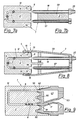
- the disposable measuring element 1 each consist of a sensor part 2 and an associated sampling part 3 as an integrated unit.
- Sensor part 2 and sampling part 3 are connected via a holder 4, which can engage in the calibration position shown and in a measuring position.
- the disposable measuring element During storage of the disposable measuring element, where it is individually packaged, there is a calibration and storage medium in the measuring channel 5 with the sensors 7 arranged in the measuring area 6, which medium is closed by closures 8, 9, 10 at the entrance and exit of the measuring channel 5 is prevented from exiting the sensor part.
- the input of the measuring channel 5, which has a coupling 11 for direct coupling of the sampling part 3, is closed by a pierceable, gas-tight membrane 8, the outlet of the measuring channel closes a deformable elastic balloon 9 in FIGS. 1 and 3 and in FIGS. 2 and 4 a further pierceable, gas-tight membrane 10.
- Grooves 13 and 14 are arranged on the housing 12 of the sensor part 2, which cooperate with engaging elements 15 on the housing 16 of the sampling part 3, the engaging elements 15 with the groove 13 also being present in the calibration position - which is also maintained during storage of the disposable measuring element the bracket 4 are engaged.
- the sample channel 17 of the sampling part 3 ends just before the pierceable membrane 8, lying coaxially to the measuring channel 5 and to the coupling 11.
- the end facing away from the membrane 8 Sample channel 17, which can be designed as a glass capillary 18 (FIGS. 1 and 2) or as a glass tube 19 (FIGS. 3 and 4), is held by the housing 16 of the sampling part 3, a connection 20 for a hollow needle 21 being present in this area .
- the hollow needle 21 is protected by a removable cap 22.
- the cap 22 of the hollow needle 21 is removed and a sample is taken.
- the sample is either sucked in by the capillary forces of the glass capillary 18 according to FIG. 1 or 2, the housing 16 having a ventilation opening 23 for pressure compensation, or actively transported by the user by pressure on an elastic region 24 of the housing 16 into the glass tube 19 .
- the cap 22 which also has a ventilation opening 25, is put back on and the measuring element 1 is inserted into an analytical device 26 shown schematically in FIG. 1, where the optical sensors 7 in the exemplary embodiment described are brought into contact with light guides 27.
- the measured values obtained via an excitation and measuring device 28 of the analysis device 26 are processed in a control and evaluation unit 29 and displayed on a display or printing unit 30.
- the individual sensors are now calibrated with the aid of the calibration medium located in the measuring channel.
- the sampling part 3 is automatically coupled to the sensor part 2 by the analysis device 26.
- a holder 33 is moved via a spindle 32 driven by a motor 31, which holder holds the sampling part 3 axially moves into the measuring position in which the engagement elements 15 of the housing 16 snap into the groove 14 of the sensor part 2.
- the glass capillary 18 of the sampling part 3 containing the sample penetrates the membrane 8 of the sensor part 2 and couples the glass capillary to the coupling 11 of the sensor part 2.
- a squeezing mechanism 25 is now operated, which causes the elastic balloon 9 to change its shape in such a way that the volume of the reservoir 36 formed by the elastic balloon 9 increases and the sample from the sample channel 17 is sucked into the measuring area 6 of the measuring channel 5.
- the reservoir 36 serves at the same time to hold the calibration medium and any excess sample.
- no calibration or sample media get into the analyzer in this embodiment.
- the disposable measuring element is removed from the analysis device 26 and thrown away.
- FIGS. 2a, b differs from that according to FIG. 1 primarily in that a further gas-tight, pierceable membrane 10 is provided at the outlet of the measuring channel 5.
- a suction device 37 shown in FIG. 2b with a suction pipe 38 is coupled to a coupling 39 of the sensor part 2.
- the suction device 37 has a piston 41 guided in a cylinder 40, the drive of which is not shown here.
- a two-point calibration can be carried out here via a barometer connection 42 of the suction pipe 38, since the calibration - when a calibration gas is present - can be carried out at two different pressure values.
- the reservoir 36 is provided here as a collecting chamber 43 between the measuring channel 5 and the membrane 10.
- areas 45, 46 are provided for temperature and level measurement.
- a further area 47 can be provided for overflow control.
- Light barriers for example, are suitable for level and overflow checks; in the simplest case, the temperature measurement takes place on the outside of the housing 12 of the sensor part 2.
- the same parts are provided with the same reference symbols.
- the sampling part 3 designed as a puncture kit and the sensor part 2 are packed separately and are only coupled together after the sampling.
- the claims are directed only to the combination of the sampling part and the sensor part.
- the sampling part 3 has a glass capillary 18 embedded in a carrier element 48 as a sample channel, which connects to a coupling element 49 for receiving a hollow needle, not shown here. After sampling and removal of the hollow needle, the sampling part 3 is connected to the coupling 11 of the sensor part 2 via the coupling element 49 and the membrane 8 is pierced.
- the glass capillary is only half-embedded in the carrier element 48 in the largest possible area of its length, the protruding part 50 of the glass capillary, which is visible above all in FIGS Thermostat comes into contact.
- the sampling part 3 has a safety volume 51, which receives excess sample accumulation during the puncture.
- the individual clutches and coupling elements 8, 49 can be designed as Luuer locks.
- the sampling part 3 shown in FIGS. 6a and 6b has a piston syringe 52 connected to the glass capillary 18 at the end opposite the coupling element 49. This is done during the sampling via the capillary necessary pressure equalization via a groove 53 between the piston 54 and cylinder 55 of the piston syringe 52. After coupling the sampling part 3 to the sensor part 2, the piston syringe is used as a pressure device for automatic or manual introduction of the sample into the measuring channel of the sensor part.
- the sensor part 2 each has a U-shaped measuring channel 5. Both the input and the output of the measuring channel 5 are on the side of the sensor part 2 facing the sampling part 3.
- the formation of an integrated unit from an interconnected measurement and sampling part is also conceivable in the embodiment variant presented last.
- the glass capillary 18 and the glass capillary 57 filled with filter wool are arranged in a housing 59 which, in the same way as shown in FIGS. 1 to 4, can be fixed in two positions with the housing 12 of the sensor part 2 via a holder 4.
- the two glass capillaries 18 and 57 are held in front of the gas-tight membrane 8, in the measuring position when the capillaries 18 and 57 snap into the couplings 11 and 56 through the membrane 8, the engagement elements 15 are connected to the groove 14. Since the sample transport depends on the suction effect of the filter wool, liquid calibration and storage media must be used.
- the input and couplings 11, 56 on the output side of the measuring channel 5 initially closed in the calibration position by conical extensions 60 of the sampling part 3.
- the sampling part 3 After removing the sampling part 3 from the sensor part 2 and rotating it by 180 °, it can be put back on the sensor part, after which - in the measuring position - connections 61 and 62 starting from the sample channel 17 or from a collecting chamber 43 in the couplings 11 or 56 engage the sensor part 2.
- the sample is then transported via suction or pumping devices, not shown here, which have already been described. With 63 a connection cone for a sampling needle is designated.
Landscapes
- Physics & Mathematics (AREA)
- Health & Medical Sciences (AREA)
- Life Sciences & Earth Sciences (AREA)
- Chemical & Material Sciences (AREA)
- Analytical Chemistry (AREA)
- Biochemistry (AREA)
- General Health & Medical Sciences (AREA)
- General Physics & Mathematics (AREA)
- Immunology (AREA)
- Pathology (AREA)
- Sampling And Sample Adjustment (AREA)
- Investigating Or Analysing Biological Materials (AREA)
- Investigating Or Analysing Materials By The Use Of Chemical Reactions (AREA)
Claims (22)
- Elément de mesure jetable qui se monte dans un appareil d'analyse pour l'analyse d'échantillons gazeux ou liquides et comporte un canal de mesure (5) rempli d'un fluide de calibrage dans une partie de capteur (2) avec au moins un capteur prévu dans la zone de mesure du canal de mesure (5), l'extrémité de sortie d'un canal d'échantillon (17) d'une partie de prélèvement d'échantillon (3) pouvant se raccorder au canal de mesure (5) et l'échantillon étant fourni par l'extrémité d'entrée du canal de mesure (5) tout en refoulant le fluide de calibrage de la zone de mesure dans un réservoir (36) relié au canal de mesure (3), pour être fourni au moins à un capteur et à l'autre extrémité du canal de mesure (5), du côté du réservoir, il est prévu un premier moyen de fermeture (9, 10), caractérisé en ce que le canal de mesure (5) est déjà pré-rempli au stockage d'un fluide de calibrage formant un fluide de conservation protecteur pour les capteurs, la partie de capteur (2) ayant, au niveau de l'extrémité d'entrée du canal de mesure (5), un moyen d'accouplement mécanique (11) pour le raccordement direct de l'extrémité de sortie du canal d'échantillon (17) à l'extrémité d'entrée du canal de mesure (5) ainsi qu'un second moyen de fermeture constitué par une première membrane (8) étanche aux gaz qui est percée par l'extrémité de sortie du canal d'échantillon (17) lors du raccordement, de sorte qu'après raccordement l'échantillon coule du canal d'échantillon (17) dans le canal de mesure (5) et la partie de prélèvement d'échantillon (3) comporte, à l'extrémité d'entrée du canal d'échantillon (17), un moyen de raccordement (20, 49) pour une canule (21).
- Elément de mesure jetable selon la revendication 1, caractérisé en ce que le réservoir (36) recevant le fluide de calibrage et de conservation ou l'échantillon, est relié en sortie au canal de mesure (5).
- Elément de mesure jetable selon la revendication 2, dont le moyen de fermeture (9, 10) à l'extrémité de sortie du canal de mesure (5) est constitué par une membrane (10) qui peut être transpercée, caractérisé en ce que le réservoir (36) pour le fluide de calibrage et de conservation ou pour l'échantillon est constitué par une chambre de réception (43) prévue entre le canal de mesure (5) et la seconde membrane (10) et la partie de capteur (2) peut être raccordée à une installation d'aspiration (37) de l'appareil d'analyse (26) après percement de la seconde membrane (10).
- Elément de mesure jetable selon la revendication 2, caractérisé en ce que le réservoir (36) est en forme de ballon (9) qui coopère avec un mécanisme d'écrasement (35) de l'appareil d'analyse (26), la modification de forme du ballon (9) provoquant une augmentation de volume du réservoir (36).
- Elément de mesure jetable selon l'une des revendications 1 à 4, caractérisé en ce que la partie de capteur (2) et la partie de prélèvement d'échantillon (3) constituent un ensemble intégré, le canal à échantillon (17) de la partie de prélèvement d'échantillon (3) se terminant dans une position de calibrage, en avant de la première membrane (8) transperçable de la partie de capteur (2) et dans une position de mesure, après percement de la première membrane (8), le canal (17) s'accroche dans le moyen d'accouplement (11) conduisant au canal de mesure (5).
- Elément de mesure jetable selon la revendication 5, caractérisé en ce que la partie de prélèvement d'échantillon (3) comporte dans le prolongement axial du canal d'échantillon (17) maintenu par le boîtier (16), une canule (21) munie d'un capuchon (22) amovible, et un dispositif de fixation (4) comprenant des rainures (13, 14) et des éléments de prise (15) étant réalisé sur le boîtier (12) de la partie de capteur (2) ainsi que sur le boîtier (16) de la partie de prélèvement d'échantillon (3), ce moyen de fixation bloquant la partie de prélèvement d'échantillon (3) dans la position de calibrage et après son coulissement axial, en position de mesure.
- Elément de mesure jetable selon la revendication 6, caractérisé en ce que le canal d'échantillon (17) est un tube capillaire en verre (18) et le boîtier (16) de la partie de prélèvement d'échantillon (3) comporte un orifice de prise d'air (23).
- Elément de mesure jetable selon la revendication 6, caractérisé en ce que le canal d'échantillon (5) est un tube de verre (19) et le boîtier (16) de la partie de prélèvement d'échantillon (3) comporte une zone élastique (24) par laquelle, par mise en oeuvre de la pression, on réalise dans le tube en verre (19), la dépression nécessaire au prélèvement de l'échantillon.
- Elément de mesure jetable selon la revendication 3, caractérisé par une membrane élastique (44) prévue dans la chambre de réception (43) de la partie de capteur (2), qui interdit au fluide de calibrage et de conservation ou à l'échantillon de sortir de l'élément de mesure (1).
- Elément de mesure jetable selon les revendications 1 à 4, caractérisé en ce que la partie de prélèvement d'échantillon (3), réalisée sous la forme d'un ensemble de ponction, comporte un tube capillaire en verre (18) et le raccord (49) pour recevoir la canule est réalisé sous la forme d'un élément d'accouplement, cet élément d'accouplement (49) pouvant être raccordé à l'élément d'accouplement (11) de la partie de capteur (2) après prélèvement de l'échantillon et enlèvement de la canule.
- Elément de mesure jetable selon la revendication 10, caractérisé en ce que la partie de prélèvement d'échantillon (3) comporte, à l'extrémité opposée à l'élément d'accouplement (49), une seringue à piston (52) et qui, après raccordement de la partie de prélèvement d'échantillon (3) sur la partie de capteur (2) constitue le dispositif de pression pour introduire l'échantillon dans le canal de mesure (5).
- Elément de mesure jetable selon la revendication 10 ou 11, caractérisé en ce que le tube capillaire en verre (18) est noyé dans une zone aussi grande que possible mais ne correspondant qu'à une partie de sa périphérie dans un élément de support (48) de la partie de prélèvement d'échantillon (3) et la partie en saillie du tube capillaire en verre (18) peut être mise en contact avec une installation thermostatique de l'appareil d'analyse.
- Elément de mesure jetable selon l'une des revendications 1 à 12, caractérisé en ce que le fluide de calibrage et de conservation est un mélange de gaz saturé de vapeur d'eau, à la pression atmosphérique, qui contient de l'oxygène à 60-160 et de préférence à 90 mm Hg en O₂ et entre 20 et 60 et de préférence 35 mm Hg en CO₂ ainsi qu'un gaz inerte, de préférence de l'azote.
- Elément de mesure jetable selon l'une des revendications 1 à 12, caractérisé en ce que le fluide de calibrage et de stockage est de l'air saturé de vapeur d'eau sous des conditions normales, aux pressions partielles de O₂ et de CO₂.
- Elément de mesure jetable selon la revendication 1, dont les deux extrémités du canal de mesure (5) rempli d'un liquide de calibrage et de conservation, sont prévues du même côté de la partie de capteur (2), caractérisé en ce que l'entrée et la sortie du canal de mesure (5) sont situées du côté de la partie de capteur (2) tournée vers la partie de prélèvement d'échantillon (3), la sortie du canal de mesure (5) comportant un autre moyen d'accouplement (56) muni d'une membrane (8) étanche aux gaz, susceptible d'être percée, et dans l'un des moyens d'accouplement (11) on peut introduire un tube capillaire en verre (18) de la partie de prélèvement d'échantillon (3) et dans l'autre moyen d'accouplement (56) on peut introduire un tube de verre (57) rempli d'un fluide d'aspiration.
- Elément de mesure jetable selon la revendication 15, caractérisé en ce que le fluide de calibrage et de conservation est une solution aqueuse équilibrée en O₂ et CO₂.
- Elément de mesure jetable selon les revendications 15 ou 16, caractérisé en ce que le tube capillaire en verre (18) de la partie de prélèvement d'échantillon (3) et un tube capillaire en verre (57) rempli d'une laine filtrante, sont alignés parallèlement pour constituer un dispositif d'aspiration en étant fixés sur une pièce d'écartement et de préhension (58).
- Elément de mesure jetable selon la revendication 17, caractérisé en ce que la partie de capteur (2) et la partie de prélèvement d'échantillon (3) forment un ensemble intégré, le tube capillaire en verre (18) de la partie de prélèvement d'échantillon (3) et le tube capillaire en verre (57) rempli d'une laine filtrante sont logés dans un boîtier (59) et le boîtier (12) de la partie de capteur (2) ainsi que le boîtier (59) de la partie de prélèvement d'échantillon (3) comportent un moyen de fixation (4) formé de rainures (13, 14) et d'éléments de prise (15), ce moyen de fixation maintenant réunis les deux tubes capillaires en verre (18, 57) dans une position de calibrage devant les membranes étanches au gaz (8) et dans une position de mesure dans les deux moyens d'accouplement (11, 56) par rapport au canal de mesure.
- Elément de mesure jetable destiné à un appareil d'analyse pour analyser des échantillons gazeux ou liquides et comportant un canal de mesure (5) rempli d'un fluide de calibrage dans une partie de capteur (2) avec au moins un capteur prévu dans une plage de mesures du canal de mesure (5) de la partie de capteur, l'extrémité de sortie d'un canal d'échantillon (17) d'une partie de prélèvement d'échantillon (3) pouvant se raccorder au canal de mesure (5) pour fournir ainsi l'échantillon par l'extrémité d'entrée du canal de mesure (5) en refoulant le fluide de calibrage dans une chambre de réception (43) d'au moins un capteur et dont l'extrémité du canal de mesure (5), du côté de la chambre de réception, comporte un moyen de fermeture (9, 10), caractérisé en ce que le canal de mesure (5) est déjà pré-rempli au stockage d'un fluide de calibrage constituant un fluide de conservation, protecteur, pour les capteurs, les deux extrémités du canal de mesure (5) se trouvant du même côté de la partie de capteur (2) et au niveau des extrémités du canal de mesure (5) tournées du côté de la partie de prélèvement d'échantillon (3), la partie de capteur (2) comporte des moyens d'accouplement mécanique (11, 56) pour raccorder directement la partie de prélèvement d'échantillon (3) à la partie de capteur (2), les moyens d'accouplement (11, 56) d'entrée et de sortie pouvant être fermés par des prolongements coniques (60) de la partie de prélèvement d'échantillon (3), cette partie de prélèvement d'échantillon (3) comportant un canal d'échantillon (17) muni d'un moyen de raccordement (63) pour une canule ainsi que la chambre de réception (43) et après enlèvement de la partie de prélèvement d'échantillon (3) par rapport à la partie de capteur (2), sa rotation de 180° et sa mise en place sur la partie de capteur, des moyens de raccordement (61, 62) en saillie de la chambre de réception (43) et du canal d'échantillon (17) viennent prendre dans les moyens d'accouplement (11, 56) de la partie de capteur (2) pour qu'après raccordement, l'échantillon coule du canal d'échantillon (17) dans le canal de mesure (5).
- Elément de mesure jetable selon l'une des revendications 1 à 19, caractérisé en ce que le canal de mesure (5) de la partie de capteur (2) comporte une zone (45, 46) prévue en aval de la plage de mesures (5) suivant le sens d'écoulement de l'échantillon, pour mesurer la température et le niveau de remplissage.
- Elément de mesure jetable selon l'une des revendications 1 à 20, caractérisé par un capteur optique (7) prévu dans la zone de mesure (6) du canal de mesure (5).
- Elément de mesure jetable selon la revendication 21, caractérisé par des capteurs optiques (7) placés dans le canal de mesure (5) de la partie de capteur (2) pour l'analyse d'échantillons sanguins, pour mesurer la valer du pH, la teneur en CO₂ et la teneur en O₂.
Applications Claiming Priority (2)
| Application Number | Priority Date | Filing Date | Title |
|---|---|---|---|
| AT2002/88A AT393565B (de) | 1988-08-09 | 1988-08-09 | Einweg-messelement |
| AT2002/88 | 1988-08-09 |
Publications (3)
| Publication Number | Publication Date |
|---|---|
| EP0354895A2 EP0354895A2 (fr) | 1990-02-14 |
| EP0354895A3 EP0354895A3 (fr) | 1991-01-30 |
| EP0354895B1 true EP0354895B1 (fr) | 1995-09-27 |
Family
ID=3525709
Family Applications (1)
| Application Number | Title | Priority Date | Filing Date |
|---|---|---|---|
| EP89890203A Expired - Lifetime EP0354895B1 (fr) | 1988-08-09 | 1989-07-31 | Elément de mesure à sens unique |
Country Status (6)
| Country | Link |
|---|---|
| US (1) | US5080865A (fr) |
| EP (1) | EP0354895B1 (fr) |
| JP (1) | JPH0750107B2 (fr) |
| AT (1) | AT393565B (fr) |
| DE (1) | DE58909451D1 (fr) |
| DK (1) | DK387289A (fr) |
Cited By (3)
| Publication number | Priority date | Publication date | Assignee | Title |
|---|---|---|---|---|
| DE19903705C1 (de) * | 1999-01-30 | 2000-07-06 | Fresenius Medical Care De Gmbh | Analysenpatrone |
| DE19903704C1 (de) * | 1999-01-30 | 2000-11-30 | Fresenius Medical Care De Gmbh | Aufnahmeeinheit für Lösungen, insbesondere Lösungen zur Kalibrierung von Sensoren zur Messung physiologisch relevanter Parameter |
| DE102010001779A1 (de) * | 2010-02-10 | 2011-08-11 | Hamilton Bonaduz Ag | Kalibrierbare Sensoreinheit für Reaktionsbehälter |
Families Citing this family (96)
| Publication number | Priority date | Publication date | Assignee | Title |
|---|---|---|---|---|
| US5564419A (en) * | 1987-11-25 | 1996-10-15 | Radiometer A/S | Method of photometric in vitro determination of the content of oxygen in a blood sample |
| DK163194C (da) * | 1988-12-22 | 1992-06-22 | Radiometer As | Fremgangsmaade ved fotometrisk in vitro bestemmelse af en blodgasparameter i en blodproeve |
| AT399228B (de) * | 1990-06-08 | 1995-04-25 | Avl Verbrennungskraft Messtech | Verfahren zur analyse von gasförmigen oder flüssigen proben und einweg-messelement zur ausübung des verfahrens |
| US5284570A (en) * | 1991-06-26 | 1994-02-08 | Ppg Industries, Inc. | Fluid sample analyte collector and calibration assembly |
| EP0520443B1 (fr) * | 1991-06-26 | 1997-01-08 | Ppg Industries, Inc. | Construction d'un capteur électrochimique |
| DE69433688T2 (de) * | 1993-10-28 | 2005-04-28 | I-Stat Corp. | Vorrichtung zur abnahme und einleitung von flüssigkeitsproben |
| AT401111B (de) * | 1995-02-01 | 1996-06-25 | Avl Verbrennungskraft Messtech | Verfahren zur kalibrierung eines ph-messelementes |
| AT407303B (de) * | 1995-07-17 | 2001-02-26 | Avl Verbrennungskraft Messtech | Verfahren zur qualitätskontrolle eines portablen analysensystems sowie flüssigkeit zur durchführung des verfahrens |
| AT403745B (de) * | 1996-02-29 | 1998-05-25 | Avl Verbrennungskraft Messtech | Messanordnung mit einem für anregungs- und messstrahlung transparentem trägerelement |
| US5747666A (en) * | 1997-03-26 | 1998-05-05 | Willis; John P. | Point-of-care analyzer module |
| US6391005B1 (en) * | 1998-03-30 | 2002-05-21 | Agilent Technologies, Inc. | Apparatus and method for penetration with shaft having a sensor for sensing penetration depth |
| AT410600B (de) | 1999-12-02 | 2003-06-25 | Hoffmann La Roche | Messkammer mit lumineszenzoptischen sensorelementen |
| US6375627B1 (en) * | 2000-03-02 | 2002-04-23 | Agilent Technologies, Inc. | Physiological fluid extraction with rapid analysis |
| US8641644B2 (en) | 2000-11-21 | 2014-02-04 | Sanofi-Aventis Deutschland Gmbh | Blood testing apparatus having a rotatable cartridge with multiple lancing elements and testing means |
| WO2002054052A1 (fr) * | 2001-01-08 | 2002-07-11 | Leonard Fish | Instruments et procedes de diagnostic permettant de detecter des analytes |
| US6902534B2 (en) * | 2001-03-30 | 2005-06-07 | Becton, Dickinson And Company | Method and kit of components for delivering blood to a portable clinical analyzer |
| US7025774B2 (en) | 2001-06-12 | 2006-04-11 | Pelikan Technologies, Inc. | Tissue penetration device |
| AU2002315180A1 (en) * | 2001-06-12 | 2002-12-23 | Pelikan Technologies, Inc. | Electric lancet actuator |
| US7981056B2 (en) | 2002-04-19 | 2011-07-19 | Pelikan Technologies, Inc. | Methods and apparatus for lancet actuation |
| US9427532B2 (en) | 2001-06-12 | 2016-08-30 | Sanofi-Aventis Deutschland Gmbh | Tissue penetration device |
| US9795747B2 (en) | 2010-06-02 | 2017-10-24 | Sanofi-Aventis Deutschland Gmbh | Methods and apparatus for lancet actuation |
| US8337419B2 (en) | 2002-04-19 | 2012-12-25 | Sanofi-Aventis Deutschland Gmbh | Tissue penetration device |
| EP1404235A4 (fr) | 2001-06-12 | 2008-08-20 | Pelikan Technologies Inc | Procede et appareil pour un dispositif de lancement de lancette integre sur une cartouche de prelevement de sang |
| DE60234598D1 (de) * | 2001-06-12 | 2010-01-14 | Pelikan Technologies Inc | Selbstoptimierende lanzettenvorrichtung mit adaptationsmittel für zeitliche schwankungen von hauteigenschaften |
| US9226699B2 (en) * | 2002-04-19 | 2016-01-05 | Sanofi-Aventis Deutschland Gmbh | Body fluid sampling module with a continuous compression tissue interface surface |
| US7491178B2 (en) | 2002-04-19 | 2009-02-17 | Pelikan Technologies, Inc. | Method and apparatus for penetrating tissue |
| US7976476B2 (en) | 2002-04-19 | 2011-07-12 | Pelikan Technologies, Inc. | Device and method for variable speed lancet |
| US7674232B2 (en) | 2002-04-19 | 2010-03-09 | Pelikan Technologies, Inc. | Method and apparatus for penetrating tissue |
| US7232451B2 (en) * | 2002-04-19 | 2007-06-19 | Pelikan Technologies, Inc. | Method and apparatus for penetrating tissue |
| US7901362B2 (en) * | 2002-04-19 | 2011-03-08 | Pelikan Technologies, Inc. | Method and apparatus for penetrating tissue |
| US7297122B2 (en) * | 2002-04-19 | 2007-11-20 | Pelikan Technologies, Inc. | Method and apparatus for penetrating tissue |
| US8702624B2 (en) * | 2006-09-29 | 2014-04-22 | Sanofi-Aventis Deutschland Gmbh | Analyte measurement device with a single shot actuator |
| US8267870B2 (en) * | 2002-04-19 | 2012-09-18 | Sanofi-Aventis Deutschland Gmbh | Method and apparatus for body fluid sampling with hybrid actuation |
| US8579831B2 (en) | 2002-04-19 | 2013-11-12 | Sanofi-Aventis Deutschland Gmbh | Method and apparatus for penetrating tissue |
| US8360992B2 (en) * | 2002-04-19 | 2013-01-29 | Sanofi-Aventis Deutschland Gmbh | Method and apparatus for penetrating tissue |
| US7892185B2 (en) * | 2002-04-19 | 2011-02-22 | Pelikan Technologies, Inc. | Method and apparatus for body fluid sampling and analyte sensing |
| WO2004054455A1 (fr) * | 2002-12-13 | 2004-07-01 | Pelikan Technologies, Inc. | Procede et appareil de mesure d'analytes |
| US20070142748A1 (en) * | 2002-04-19 | 2007-06-21 | Ajay Deshmukh | Tissue penetration device |
| US8784335B2 (en) | 2002-04-19 | 2014-07-22 | Sanofi-Aventis Deutschland Gmbh | Body fluid sampling device with a capacitive sensor |
| US7648468B2 (en) * | 2002-04-19 | 2010-01-19 | Pelikon Technologies, Inc. | Method and apparatus for penetrating tissue |
| US7229458B2 (en) | 2002-04-19 | 2007-06-12 | Pelikan Technologies, Inc. | Method and apparatus for penetrating tissue |
| US9248267B2 (en) | 2002-04-19 | 2016-02-02 | Sanofi-Aventis Deustchland Gmbh | Tissue penetration device |
| US7892183B2 (en) * | 2002-04-19 | 2011-02-22 | Pelikan Technologies, Inc. | Method and apparatus for body fluid sampling and analyte sensing |
| US7175642B2 (en) * | 2002-04-19 | 2007-02-13 | Pelikan Technologies, Inc. | Methods and apparatus for lancet actuation |
| US7909778B2 (en) | 2002-04-19 | 2011-03-22 | Pelikan Technologies, Inc. | Method and apparatus for penetrating tissue |
| US7547287B2 (en) * | 2002-04-19 | 2009-06-16 | Pelikan Technologies, Inc. | Method and apparatus for penetrating tissue |
| US8221334B2 (en) * | 2002-04-19 | 2012-07-17 | Sanofi-Aventis Deutschland Gmbh | Method and apparatus for penetrating tissue |
| US7331931B2 (en) * | 2002-04-19 | 2008-02-19 | Pelikan Technologies, Inc. | Method and apparatus for penetrating tissue |
| US9314194B2 (en) * | 2002-04-19 | 2016-04-19 | Sanofi-Aventis Deutschland Gmbh | Tissue penetration device |
| US9795334B2 (en) | 2002-04-19 | 2017-10-24 | Sanofi-Aventis Deutschland Gmbh | Method and apparatus for penetrating tissue |
| US7198606B2 (en) * | 2002-04-19 | 2007-04-03 | Pelikan Technologies, Inc. | Method and apparatus for a multi-use body fluid sampling device with analyte sensing |
| US20040067481A1 (en) * | 2002-06-12 | 2004-04-08 | Leslie Leonard | Thermal sensor for fluid detection |
| US8574895B2 (en) | 2002-12-30 | 2013-11-05 | Sanofi-Aventis Deutschland Gmbh | Method and apparatus using optical techniques to measure analyte levels |
| US20070032812A1 (en) * | 2003-05-02 | 2007-02-08 | Pelikan Technologies, Inc. | Method and apparatus for a tissue penetrating device user interface |
| DE602004028463D1 (de) | 2003-05-30 | 2010-09-16 | Pelikan Technologies Inc | Verfahren und vorrichtung zur injektion von flüssigkeit |
| WO2004107964A2 (fr) * | 2003-06-06 | 2004-12-16 | Pelikan Technologies, Inc. | Procede et appareil d'echantillonnage de fluides anatomiques et d'examen de l'analysat |
| WO2006001797A1 (fr) | 2004-06-14 | 2006-01-05 | Pelikan Technologies, Inc. | Element penetrant peu douloureux |
| WO2005006939A2 (fr) * | 2003-06-11 | 2005-01-27 | Pelikan Technologies, Inc. | Procede et appareil d'echantillonnage de liquide corporel et de detection d'analyte |
| US8282576B2 (en) | 2003-09-29 | 2012-10-09 | Sanofi-Aventis Deutschland Gmbh | Method and apparatus for an improved sample capture device |
| EP1680014A4 (fr) * | 2003-10-14 | 2009-01-21 | Pelikan Technologies Inc | Procede et appareil fournissant une interface-utilisateur variable |
| EP1706026B1 (fr) | 2003-12-31 | 2017-03-01 | Sanofi-Aventis Deutschland GmbH | Procédé et appareil permettant d'améliorer le flux fluidique et le prélèvement d'échantillons |
| US7822454B1 (en) * | 2005-01-03 | 2010-10-26 | Pelikan Technologies, Inc. | Fluid sampling device with improved analyte detecting member configuration |
| US10478179B2 (en) * | 2004-04-27 | 2019-11-19 | Covidien Lp | Absorbable fastener for hernia mesh fixation |
| US9101302B2 (en) * | 2004-05-03 | 2015-08-11 | Abbott Diabetes Care Inc. | Analyte test device |
| WO2006011062A2 (fr) * | 2004-05-20 | 2006-02-02 | Albatros Technologies Gmbh & Co. Kg | Hydrogel imprimable pour biocapteurs |
| US9775553B2 (en) | 2004-06-03 | 2017-10-03 | Sanofi-Aventis Deutschland Gmbh | Method and apparatus for a fluid sampling device |
| WO2005120365A1 (fr) | 2004-06-03 | 2005-12-22 | Pelikan Technologies, Inc. | Procede et appareil pour la fabrication d'un dispositif d'echantillonnage de liquides |
| DE102004033317A1 (de) * | 2004-07-09 | 2006-02-09 | Roche Diagnostics Gmbh | Analytisches Testelement |
| US20080214917A1 (en) * | 2004-12-30 | 2008-09-04 | Dirk Boecker | Method and apparatus for analyte measurement test time |
| WO2006072004A2 (fr) * | 2004-12-30 | 2006-07-06 | Pelikan Technologies, Inc. | Procede et dispositif pour temps d'essai de mesure d'analyte |
| US8652831B2 (en) | 2004-12-30 | 2014-02-18 | Sanofi-Aventis Deutschland Gmbh | Method and apparatus for analyte measurement test time |
| US20060167382A1 (en) * | 2004-12-30 | 2006-07-27 | Ajay Deshmukh | Method and apparatus for storing an analyte sampling and measurement device |
| US20060184065A1 (en) * | 2005-02-10 | 2006-08-17 | Ajay Deshmukh | Method and apparatus for storing an analyte sampling and measurement device |
| US20070276290A1 (en) * | 2005-10-04 | 2007-11-29 | Dirk Boecker | Tissue Penetrating Apparatus |
| US20070191736A1 (en) * | 2005-10-04 | 2007-08-16 | Don Alden | Method for loading penetrating members in a collection device |
| US20090196580A1 (en) * | 2005-10-06 | 2009-08-06 | Freeman Dominique M | Method and apparatus for an analyte detecting device |
| US7485849B2 (en) * | 2006-05-03 | 2009-02-03 | The United States Of America As Represented By The Secretary Of The Army | Light sensor protection and method for protecting a light sensor with laser radiation attenuating gas |
| EP2016393A2 (fr) * | 2006-05-05 | 2009-01-21 | Dublin City University | Sonde optique |
| CA2686673C (fr) * | 2007-05-15 | 2016-09-20 | O.I. Corporation D.B.A. O.I. Analytical | Analyse et prelevement d'echantillon de gaz |
| US8191437B2 (en) * | 2007-05-15 | 2012-06-05 | O.I. Corporation | Gas sample collection and analysis |
| US20090209883A1 (en) * | 2008-01-17 | 2009-08-20 | Michael Higgins | Tissue penetrating apparatus |
| WO2009126900A1 (fr) * | 2008-04-11 | 2009-10-15 | Pelikan Technologies, Inc. | Procédé et appareil pour dispositif de détection d’analyte |
| EP2389289A4 (fr) * | 2009-01-23 | 2012-11-07 | Univ Drexel | Appareil et procédés de détection d'une inflammation à l'aide de points quantiques |
| US9375169B2 (en) * | 2009-01-30 | 2016-06-28 | Sanofi-Aventis Deutschland Gmbh | Cam drive for managing disposable penetrating member actions with a single motor and motor and control system |
| DE102009007616A1 (de) * | 2009-02-05 | 2010-08-12 | Gaudlitz Gmbh | Testvorrichtung für Flüssigkeiten des menschlichen oder tierischen Körpers |
| US8965476B2 (en) | 2010-04-16 | 2015-02-24 | Sanofi-Aventis Deutschland Gmbh | Tissue penetration device |
| DE102013011343B3 (de) * | 2013-07-01 | 2014-07-10 | Alfred-Wegener-Institut Helmholtz-Zentrum für Polar- und Meeresforschung | Diffusionskammer zur Ermittlung unterschiedlicher Parameter einer wässrigen Substanz |
| DE202013103647U1 (de) | 2013-08-12 | 2013-09-02 | Aspect Imaging Ltd. | Ein System zum Online-Messen und Steuern von O2-Fraktion, CO-Fraktion und CO2-Fraktion |
| US9897570B2 (en) * | 2013-08-22 | 2018-02-20 | Horiba Advanced Techno, Co., Ltd. | Dissolved oxygen measurement system and method of calibrating dissolved oxygen meter |
| EP2887071B1 (fr) | 2013-12-19 | 2018-12-05 | F. Hoffmann-La Roche AG | Récipient et fourniture de supports de cuve |
| US10598580B2 (en) * | 2014-12-19 | 2020-03-24 | Health Onvector Inc | Viscometers and methods of measuring liquid viscosity |
| DE102018105174B4 (de) | 2018-03-07 | 2020-03-12 | Presens Precision Sensing Gmbh | Analyseeinheit |
| US11360065B2 (en) * | 2018-03-16 | 2022-06-14 | Teledyne Flir Detection, Inc. | Calibration systems and methods for analyte detectors |
| US12137885B2 (en) * | 2020-03-27 | 2024-11-12 | Senju Pharmaceutical Co., Ltd. | Bodily fluid collection device |
| DE102020115791A1 (de) | 2020-06-16 | 2021-12-16 | Presens Precision Sensing Gmbh | Sensoreinheit, messverfahren und herstellungsverfahren |
| WO2022015763A1 (fr) * | 2020-07-13 | 2022-01-20 | Buckman Laboratories International, Inc. | Dispositif et procédé d'étalonnage de fluoromètre |
Citations (3)
| Publication number | Priority date | Publication date | Assignee | Title |
|---|---|---|---|---|
| US4342964A (en) * | 1978-12-04 | 1982-08-03 | Transidyne General Corp. | Apparatus for electrochemical measurements |
| EP0121742A2 (fr) * | 1983-04-11 | 1984-10-17 | Roche Diagnostics GmbH | Dispositif d'analyse électrochimique de composants électrolytiques dans un fluide à examiner |
| EP0122420A2 (fr) * | 1983-04-11 | 1984-10-24 | Roche Diagnostics GmbH | Système d'électrodes pour l'analyse électrochimique des constituants d'un liquide |
Family Cites Families (14)
| Publication number | Priority date | Publication date | Assignee | Title |
|---|---|---|---|---|
| US3224436A (en) * | 1961-04-10 | 1965-12-21 | Honeywell Regulator Co | Hypodermic apparatus for measuring hydrogen ion concentration of blood within a living body |
| AT278710B (de) * | 1968-04-30 | 1970-02-10 | H C Hans Dipl Ing Dr Dr List | Meßeinrichtung zur Bestimmung des pH-Wertes einer Blutprobe |
| US3640267A (en) * | 1969-12-15 | 1972-02-08 | Damon Corp | Clinical sample container |
| CH635431A5 (de) * | 1979-02-08 | 1983-03-31 | Ciba Geigy Ag | Probenaufgabevorrichtung fuer gaschromatographen. |
| US4289648A (en) * | 1979-03-20 | 1981-09-15 | Ortho Diagnostics, Inc. | Blood gas controls composition, method and apparatus |
| EP0133326A3 (fr) * | 1983-06-27 | 1985-04-03 | Diversified Medical Technologies, Inc. | Dispositif analysateur d'haleine jetable après usage |
| US4627893A (en) * | 1984-03-28 | 1986-12-09 | Amdev, Inc. | Means and methods for quantitative determination of analyte in liquids |
| US4654127A (en) * | 1984-04-11 | 1987-03-31 | Sentech Medical Corporation | Self-calibrating single-use sensing device for clinical chemistry and method of use |
| WO1985004719A1 (fr) * | 1984-04-11 | 1985-10-24 | Sentech Medical Corporation | Dispositif de detection a utilisation unique et a autocalibrage pour un appareil d'analyse chimique clinique |
| US4627445A (en) * | 1985-04-08 | 1986-12-09 | Garid, Inc. | Glucose medical monitoring system |
| JPS61286738A (ja) * | 1985-06-14 | 1986-12-17 | オ−デイオバイオニクス インコ−ポレイテツド | 医療用システム |
| US4786394A (en) * | 1985-08-29 | 1988-11-22 | Diamond Sensor Systems, Inc. | Apparatus for chemical measurement of blood characteristics |
| DE3774680D1 (de) * | 1986-12-22 | 1992-01-02 | Siemens Ag | Anordnung zur untersuchung eines fluessigen mediums und verfahren zum betrieb der anordnung. |
| US4871439A (en) * | 1987-02-05 | 1989-10-03 | Steven Enzer | Disposable self-calibratable electrode package |
-
1988
- 1988-08-09 AT AT2002/88A patent/AT393565B/de not_active IP Right Cessation
-
1989
- 1989-07-31 EP EP89890203A patent/EP0354895B1/fr not_active Expired - Lifetime
- 1989-07-31 DE DE58909451T patent/DE58909451D1/de not_active Expired - Fee Related
- 1989-08-08 US US07/390,754 patent/US5080865A/en not_active Expired - Lifetime
- 1989-08-08 DK DK387289A patent/DK387289A/da not_active Application Discontinuation
- 1989-08-09 JP JP1207778A patent/JPH0750107B2/ja not_active Expired - Fee Related
Patent Citations (3)
| Publication number | Priority date | Publication date | Assignee | Title |
|---|---|---|---|---|
| US4342964A (en) * | 1978-12-04 | 1982-08-03 | Transidyne General Corp. | Apparatus for electrochemical measurements |
| EP0121742A2 (fr) * | 1983-04-11 | 1984-10-17 | Roche Diagnostics GmbH | Dispositif d'analyse électrochimique de composants électrolytiques dans un fluide à examiner |
| EP0122420A2 (fr) * | 1983-04-11 | 1984-10-24 | Roche Diagnostics GmbH | Système d'électrodes pour l'analyse électrochimique des constituants d'un liquide |
Cited By (3)
| Publication number | Priority date | Publication date | Assignee | Title |
|---|---|---|---|---|
| DE19903705C1 (de) * | 1999-01-30 | 2000-07-06 | Fresenius Medical Care De Gmbh | Analysenpatrone |
| DE19903704C1 (de) * | 1999-01-30 | 2000-11-30 | Fresenius Medical Care De Gmbh | Aufnahmeeinheit für Lösungen, insbesondere Lösungen zur Kalibrierung von Sensoren zur Messung physiologisch relevanter Parameter |
| DE102010001779A1 (de) * | 2010-02-10 | 2011-08-11 | Hamilton Bonaduz Ag | Kalibrierbare Sensoreinheit für Reaktionsbehälter |
Also Published As
| Publication number | Publication date |
|---|---|
| EP0354895A2 (fr) | 1990-02-14 |
| EP0354895A3 (fr) | 1991-01-30 |
| AT393565B (de) | 1991-11-11 |
| DE58909451D1 (de) | 1995-11-02 |
| JPH0750107B2 (ja) | 1995-05-31 |
| US5080865A (en) | 1992-01-14 |
| DK387289D0 (da) | 1989-08-08 |
| DK387289A (da) | 1990-02-10 |
| JPH02167474A (ja) | 1990-06-27 |
| ATA200288A (de) | 1991-04-15 |
Similar Documents
| Publication | Publication Date | Title |
|---|---|---|
| EP0354895B1 (fr) | Elément de mesure à sens unique | |
| DE10057832C1 (de) | Blutanalysegerät | |
| DE69433688T2 (de) | Vorrichtung zur abnahme und einleitung von flüssigkeitsproben | |
| DE2927048C2 (de) | Vorrichtung zur Durchführung analytischer Messungen an einer Flüssigkeit | |
| DE68918598T2 (de) | In vitro photometrisches verfahren zur bestimmung des sauerstoffgehaltes in einer blutprobe. | |
| DE3416956C2 (de) | Meßvorrichtung zur Bestimmung der Aktivität oder der Konzentration von Ionen in Lösungen | |
| EP1621132B1 (fr) | Dispositif et procédé pour le prélèvement et l'analyse de liquides corporels | |
| DE60303987T2 (de) | Flüssigkeitssensor mit integrierter Lanzette | |
| EP0722567B1 (fr) | Dispositif de mesure destine a l'analyse de fluides | |
| DE69732003T2 (de) | Reagenztestvorrichtung in Form eines hohlen Kegel- oder Pyramidenstumpfs | |
| DE9417612U1 (de) | Probenabnahmegerät | |
| EP0460343B1 (fr) | Elément de mesure à usage unique pour l'analyse d'un échantillon liquide ou gazeux | |
| DE69430708T2 (de) | Vorrichtung zum Gebrauch bei transdermischen Infusionen | |
| DE10010587A1 (de) | System zur Bestimmung von Analytkonzentrationen in Körperflüssigkeiten | |
| DE69925210T2 (de) | Spitze für eine Saugvorrichtung | |
| DE3850867T2 (de) | Blutentnahmevorrichtung. | |
| DE102004033317A1 (de) | Analytisches Testelement | |
| EP0121742B1 (fr) | Dispositif d'analyse électrochimique de composants électrolytiques dans un fluide à examiner | |
| WO2007093150A1 (fr) | Procédé et dispositif d'aspiration d'un volume, notamment de prélèvement d'un échantillon aux fins d'analyse à l'aide d'un dispositif de chromatographie en phase liquide | |
| DE102014203815A1 (de) | Verfahren zur Weinanalyse und zugehörige Vorrichtung | |
| DE3217591C2 (de) | Analysengerät zur Untersuchung von durch Luftpakete und/oder Standardflüssigkeit getrennten Flüssigkeitsproben | |
| DE2534255C3 (de) | Verfahren und Vorrichtung zur Probenentnahme von im Blut gelösten Gasen | |
| DE2741914C3 (de) | Vorrichtung zum Eichen eines spektralselektiven, eine Lichtleitersonde aufweisenden photometrischen Meßsstems | |
| EP2389097B1 (fr) | Système et procédé destinés à l'analyse d'un liquide corporel | |
| JPH0560538B2 (fr) |
Legal Events
| Date | Code | Title | Description |
|---|---|---|---|
| PUAI | Public reference made under article 153(3) epc to a published international application that has entered the european phase |
Free format text: ORIGINAL CODE: 0009012 |
|
| AK | Designated contracting states |
Kind code of ref document: A2 Designated state(s): DE FR GB |
|
| GBC | Gb: translation of claims filed (gb section 78(7)/1977) | ||
| RAP1 | Party data changed (applicant data changed or rights of an application transferred) |
Owner name: AVL MEDICAL INSTRUMENTS AG |
|
| EL | Fr: translation of claims filed | ||
| PUAL | Search report despatched |
Free format text: ORIGINAL CODE: 0009013 |
|
| AK | Designated contracting states |
Kind code of ref document: A3 Designated state(s): DE FR GB |
|
| 17P | Request for examination filed |
Effective date: 19901220 |
|
| RHK1 | Main classification (correction) |
Ipc: A61B 5/14 |
|
| 17Q | First examination report despatched |
Effective date: 19930202 |
|
| GRAA | (expected) grant |
Free format text: ORIGINAL CODE: 0009210 |
|
| AK | Designated contracting states |
Kind code of ref document: B1 Designated state(s): DE FR GB |
|
| PG25 | Lapsed in a contracting state [announced via postgrant information from national office to epo] |
Ref country code: FR Effective date: 19950927 |
|
| REF | Corresponds to: |
Ref document number: 58909451 Country of ref document: DE Date of ref document: 19951102 |
|
| GBT | Gb: translation of ep patent filed (gb section 77(6)(a)/1977) |
Effective date: 19951120 |
|
| EN | Fr: translation not filed | ||
| PLBE | No opposition filed within time limit |
Free format text: ORIGINAL CODE: 0009261 |
|
| STAA | Information on the status of an ep patent application or granted ep patent |
Free format text: STATUS: NO OPPOSITION FILED WITHIN TIME LIMIT |
|
| 26N | No opposition filed | ||
| REG | Reference to a national code |
Ref country code: GB Ref legal event code: IF02 |
|
| PGFP | Annual fee paid to national office [announced via postgrant information from national office to epo] |
Ref country code: GB Payment date: 20030730 Year of fee payment: 15 |
|
| PGFP | Annual fee paid to national office [announced via postgrant information from national office to epo] |
Ref country code: DE Payment date: 20030807 Year of fee payment: 15 |
|
| PG25 | Lapsed in a contracting state [announced via postgrant information from national office to epo] |
Ref country code: GB Free format text: LAPSE BECAUSE OF NON-PAYMENT OF DUE FEES Effective date: 20040731 |
|
| PG25 | Lapsed in a contracting state [announced via postgrant information from national office to epo] |
Ref country code: DE Free format text: LAPSE BECAUSE OF NON-PAYMENT OF DUE FEES Effective date: 20050201 |
|
| GBPC | Gb: european patent ceased through non-payment of renewal fee |
Effective date: 20040731 |