EP0354908B1 - Rauschverminderung bei fernsehsignalen - Google Patents
Rauschverminderung bei fernsehsignalen Download PDFInfo
- Publication number
- EP0354908B1 EP0354908B1 EP88902889A EP88902889A EP0354908B1 EP 0354908 B1 EP0354908 B1 EP 0354908B1 EP 88902889 A EP88902889 A EP 88902889A EP 88902889 A EP88902889 A EP 88902889A EP 0354908 B1 EP0354908 B1 EP 0354908B1
- Authority
- EP
- European Patent Office
- Prior art keywords
- emphasis
- signal
- linear
- characteristic
- circuit
- Prior art date
- Legal status (The legal status is an assumption and is not a legal conclusion. Google has not performed a legal analysis and makes no representation as to the accuracy of the status listed.)
- Expired - Lifetime
Links
Images





Classifications
-
- H—ELECTRICITY
- H04—ELECTRIC COMMUNICATION TECHNIQUE
- H04N—PICTORIAL COMMUNICATION, e.g. TELEVISION
- H04N5/00—Details of television systems
- H04N5/14—Picture signal circuitry for video frequency region
- H04N5/21—Circuitry for suppressing or minimising disturbance, e.g. moiré or halo
-
- H—ELECTRICITY
- H04—ELECTRIC COMMUNICATION TECHNIQUE
- H04N—PICTORIAL COMMUNICATION, e.g. TELEVISION
- H04N11/00—Colour television systems
- H04N11/24—High-definition television systems
Definitions
- the present invention relates to noise reduction in television signals, in particular to noise reduction in high definition television signals such as, the example, High Definition Multiplexed Analogue Component (HD MAC) television signals transmitted as F.M.
- high definition television signals such as, the example, High Definition Multiplexed Analogue Component (HD MAC) television signals transmitted as F.M.
- HD MAC High Definition Multiplexed Analogue Component
- High definition television signals have increased noise problems over conventional T.V. signals.
- a further problem in this respect relates to the fact that in some cases it may be desirable to transmit a high definition T.V. signal together with a conventional signal, in the form of a "compound" signal.
- a conventional signal in the form of a "compound" signal.
- An example is HD MAC, which is, in fact, comprised of a conventional MAC signal together with additional information necessary to make up the high definition signal.
- a conventional MAC receiver will just utilise the conventional MAC signal, whereas a receiver adapted for HD MAC will utilise the complete signal to reproduce the high definition picture and sound.
- Any noise reduction technique applied to reduce the added noise problems of a high definition signal should, therefore, be such as not to affect undesirably any conventional signal transmitted with the high definition signal in a compound signal, ie compatibility with transmission and processing of conventional signals such as may be processed by already existing techniques, needs to be ensured.
- the non-linear pre and de-emphasis applied to the high frequency sub-band advantageously gives adequate noise reduction to a high definition television signal to give an acceptable received signal.
- the frequency split and non-linear function are preferably arranged such that any conventional signal transmitted with the high definition signal is substantially unaffected by the processing, in the sense that the conventional signal may still be acceptably reproduced on a conventional receiver which is not arranged to be able to process a high definition signal.
- the low frequency band does not have the pre/de emphasis characteristic applied thereto results in no appreciable degredation of the high definition signal either, as both noise and adjacent channel interference increase as frequency increases, and it is therefore the higher frequencies which are the most crucial as regards the noise in the transmitted signal.
- the filter characteristics applied to the signal are chosen bearing in mind the effect on compatibility with conventional processing as against noise reduction effects for the high definition signal. The more of the signal is filtered for pre-emphasis (and noise reduction) the more compatibility is likely to be effected. A compromise is necessary.
- the non-linear pre/de-emphasis characteristic applied is preferably such that a maximum amplitude voltage signal is unaffected.
- a 1V multiburst input having the pre-emphasis of the present invention applied to it will come out as a 1V multiburst.
- the amplitude decreases the amount of pre-emphasis applied will increase, and vice versa for the de-emphasis characteristic.
- the non-linear characteristic is further preferably arranged such that its effect is symmetric independent effects due to static deviation are eliminated.
- the non-linear characteristic is preferably arranged to become linear, such that threshold spikes pass through relatively undistorted, and the system therefore does not introduce any worsening to F.M. threshold.
- the non-linear characteristic (voltage in/voltage out) is preferably arranged in the form of a three part curve having a middle and two ends, the middle having a certain slope value and the two end portions having slope values which are the same as each other but which are different from the slope value of the middle portion.
- This non-linear characteristic may be arranged as a piece wise linear function (three straight parts put together). However, we have found that more benefits accrue of the function is formed as a continuous curve.
- the present invention can be implemented via either digital or analogue processing techniques, a problem in either technique is that it is desirable to ensure that both the pre and de-emphasis characteristics are complementary (i.e. "mirror" images of each other), otherwise errors will be introduced by the processing.
- the present invention preferably provides analogue pre-emphasis circuitry for applying non-linear pre-emphasis to a high definition television signal, the circuity comprising a feedback loop which includes means for applying a de-emphasis characteristic to the fedback signal, the de-emphasis characteristic corresponding to the de-emphasis characteristic to be applied to the pre-emphasised signal after processing by the pre-emphasis circuity
- a feedback loop which includes means for applying a de-emphasis characteristic to the fedback signal, the de-emphasis characteristic corresponding to the de-emphasis characteristic to be applied to the pre-emphasised signal after processing by the pre-emphasis circuity
- the transfer function necessary for the pre-corrector could be implemented by means of a digital filter with non-linear co-efficients.
- the filter necessary to implement such a transfer function would be extremely complex, and such a filter has not yet been designed.
- the present invention further provides a pre-corrector circuit for a high definition television signal the circuit being arranged to correct, prior to pre-emphasis, for errors due to not fully complementary pre and de-emphasis being applied to the signal, the circuit comprising filter means for filtering the signal to provide at least two frequency bands, means for applying a non-linear transfer function to one of the frequency band, and means for recombining the frequency bands.
- the desired filter and transfer function responses can be calculated, as we are aware of the frequency response required of the pre-corrector for any given input level, by a logical design process, which is examplified in the following description of the specific embodiment.
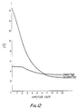
- the frequency response (see figure 8) for the digital pre/de emphasis is non linear for different frequency values and the response is different for each voltage value.
- the pre-corrector is preferably designed by choosing a non-linear transfer function for one reference frequency, such that all voltages will be correctly compensated for at the reference frequency. As two filters are provided in the pre-corrector, two other voltages can then be corrected for at other frequencies. The overall effect is to bring the curves shown in Figure 8 closer to each other and the base line. With more filter functions it would be possible to provide correction for a further voltage values.
- the pre-corrector can be designed to act to correct channel error as well as error due to non-complementary pre and de-emphasis characteristics.
- Non-linear pre-emphasis is a process where the pre-emphasised vision waveform is compressed at the transmitter to reduce the peak to peak frequency deviation and de-compressed at the receiver.
- pre-emphasis is applied to the HDMAC signal by filtering the signal to split it into a high and low frequency sub-band, and the high frequency sub-band is passed through a non-linear transfer function.
- De-emphasis is applied at the receiver in a similar manner. This gives a processed HDMAC signal in which the noise is of an acceptable level, and also one which is compatible with existing MAC receivers, such that no appreciable degredation occurs to the conventional MAC signal due to the extra processing.
- the present invention may be implemented by analogue or digital means.
- F1 and F0 are single pole high pass and low pass filters.
- F2 is a single pole low pass filter.
- N1 is a non-linear function.
- the following equations relate to the filter characteristics; PROPOSED VALUES FOR HD MAC.
- F0 2.5 MHz
- F1 3 MHz
- F2 10.125 MHz
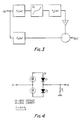
- the transfer circuit is implemented ( Figure 4) via diodes, D1 and D2, and resistor RL.
- the transfer function is difficult to translate into explicit form, but it has been evaluated and a typical transfer function for HD MAC is shown in Figure 5.
- Figure 5 is expressed in terms of peak to peak voltage. If it were expressed in terms of straightforward voltage the curve would continue through the origin as a mirror immage of the curve shown, giving the 3 part transfer function (end portions having the same slope and mid portion having a different slope - see, eg . the graphical representation on N1 of Figure 3) referred to in the preamble.
- Diodes D1 and D2, and associated bias circuits may be on a chip. It is not possible to easily temperature compensate the response, so it is preferable to temperature control the chip by, eg an on-chip power transistor.
- the high frequency and low frequency parts of the signal are separated by F0, F1 and the high frequency part is subjected to the non-linear transfer function N1 and then filtered by F2.
- Noise conversion affects due to static deviation are eliminated since the non-linearity is symmetric independent of static deviation.
- the processed high frequency component is re-combined with the low frequency component. In the absence of the non-linear function and F2, an overall flat frequency response would be ontained by employing equal cut of frequencies F0, F1.
- the function is designed to give a near flat forward frequency response for a full amplitude multi-burst signal. This requires F0 to be greater than F1 due to the affect of the non-linear function. As the input level is reduced, the frequency response drops and for very small input signal attenuation is designed to be 6dB at the top of the video baseband. This value is significant in that it is the minimum value that is expected to guarantee compliance with WARC 77.
- the pre-emphasis network is defined as the inverse function of the de-emphasis network. Due to the non-linearity, it will produce out-of-band cpmponents which will be largely filtered off by the channel.
- the curves are designed to provide a nominal 6dB attenuation for low input levels at 9.46 MHz. This is the lowest frequency for static interfering tones (1st A.C.I.).
- the full noise improvement is obtained for signals of -20dB or less.
- the level of the first ACI static tone has been calculated to be approximately -20dB for an interferer at the WARC 77 worst case limit, so that a full 6dB improvement is obtained.
- the noise improvement will reduce, and for this reason it is important to include a band limiting filter between the FM demodulator and the de-emphasis processing. Under these conditions, practical tests have shown the system to be still effective for C/N ratios down to 5dB. For a test signal consisting of a full amplitude high frequency grating there will be no noise improvements, but under these conditions, the noise is subjectively less noticable.
- a pre-emphasis network is illustrated in Figure 2.
- a de-emphasis network is placed in a feedback loop to an amplifier 2, the de-emphasis network 1 having the same characteristics as the de-emphasis network which is utilized to provide the actual de-emphasis ( Figure 3).
- the signal to be pre-emphasised is input to the amplifier 2 and the pre-emphasised signal is taken from the output of the amplifier 2. So long as the loop is stable, and so long as the loop bandwidth is sufficiently high, the pre-emphasis function is accurately generated.
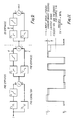
- FIGS 7a and 7b illustrate, in schematic block diagram form, digital circuit implementation of the pre-emphasis and de-emphasis characteristics in accordance with the present invention.
- the de-emphasis function is provided by high and low pass filters F1, F2 (which may have the same characteristics as those illustrated in Figure 1), which may be digital filters, and a non-linear transfer function N1, which also may be implemented digitally.
- the pre-emphasis function ( Figure 7b) is provided by corresponding filters, F1, F2, and a transfer function N2, which may be implemented digitally.
- the non-linear function N2 is the inverse of the non-linear function N1.
- the basic configuration is the same for pre-emphasis and de-emphasis.
- filters F1, F2 the maximum flexibility is obtained in the overall design. Under some circumstances it may be possible to make filters F1, F2, truly complimentary in order to simplify hardware design. A single filter only is then required as shown in the embodiments illustrated in Figures 14 and 15.
- the error can be reduced to some extent.
- FIG. 9 is a schematic block diagram of an overall system implemented digitally.
- the pre-corrector here is of the same configuration as the pre- and de-emphasis networks.
- F3 would typically be a bandpass filter with zero response at dc and at the top of the baseband.
- F4 would typically be a near complimentary band stop filter with unity response at dc and at the top of the baseband.
- Fig. 12 indicates the level of ISI generated by the system with and without pre-correction.
- ISI inter sample interference
- the FM channel is non-linear, so ISI will be level dependent. A single value of ISI will therefore not be sufficient, and it will be necessary to specify ISI for various signal levels.
- Figure 11 shows the definition used in this paper.
- the test signal is a pseudo-random binary sequence of amplitude v pk-pk.
- the inter-sample interference is defined as the maximum value of the modulus of the error, expressed as a percentage of the pk to pk test signal amplitude.
- the test signal is symmetrical about mid-grey level.
- the error is defined as the difference between the sample value at the output of the test system and the sample value which would result as calculated from the dc gain of the test system.
- FR reference frequency
- F(R) and F4(R) are the only variables in the design process.
- the design process is repeated for a range of values FR and F4 (FR).
- the ISI/amplitude curve is calculated for each result and the best compromise chosen.
- Equation (2) is easily solved for F3(F) by an interation process.
- F4(F) is calculated from equation (1).
- VI1 is chosen to be 1Vp-p. The guarantees that a 1Vp-p multiburst test signal will not result in over deviation of the carrier. (In the case of pseudo random sample there will still be some small over deviation).
- V12 is chosen as 0.2p-p. At this level, contributions to ISI from other sources are small, so the contribution from E7 should be minimised.
- This logical design process may easily be applied by a computer program.
- a surprising effect of the pre-corrector is that it can also be designed to correct for intersample interference produced by the r.f. channel in a satellite T.V. system.
- Figure 6 shows a frequency response for the de-emphasis network of Figure 9.
- HD MAC high definition signals
- W MAC high definition signals
- the present invention also may provide a pre-corrector which is arranged to correct for intersample interference produced by the r.f. channel in a television signal transmission and reception system.
Landscapes
- Engineering & Computer Science (AREA)
- Multimedia (AREA)
- Signal Processing (AREA)
- Reduction Or Emphasis Of Bandwidth Of Signals (AREA)
- Picture Signal Circuits (AREA)
- Input Circuits Of Receivers And Coupling Of Receivers And Audio Equipment (AREA)
- Details Of Television Scanning (AREA)
- Television Systems (AREA)
Claims (12)
- Ein Verfahren zum Verarbeiten eines Hochauflösungs-Fernsehsignals, das die Schritte umfaßt:
Filtern des Signals, um ein hochfrequentes Unterband und ein niederfrequentes Unterband zu ergeben;
Anwenden einer nichtlinearen Vorverzerrungs-Charakteristik auf das hochfrequente Unterband, die im wesentlichen komplementär zu einer Funktion der Form ist:

worin Vi = Eingangsspannung, Vo = Ausgangsspannung, q = Ladung des Elektrons, K = Boltzmann-Konstante, T = absolute Temperatur und V und M Formfaktoren sind;
Rekombinieren und Übertragen des Signals;
Empfangen des Signals;
Filtern des empfangenen Signals, um ein hochfrequentes und niederfrequentes Unterband zu schaffen;
Anwenden einer nichtlinearen Nachentzerrungs-Charakteristik der durch die obige Gleichung (1) gegebenen Form auf das hochfrequente Unterband; und
Rekombinieren des Signals. - Ein Verfahren zum Verarbeiten eines Hochauflösungs-Fernsehsignals gemäß Anspruch 1, bei dem die Verarbeitung durch eine analoge Schaltkreiseinrichtung durchgeführt wird und die Schritte des Filterns des Signals und des Anwendens einer nichtlinearen Vorverzerrungs-Charakteristik auf das hochfrequente Unterband desselben durch den einzigen Schritt des Anwendens des Signals auf eine Rückkopplungsschleife durchgeführt wird, wobei der Rückkopplungspfad der Rückkopplungsschleife eine Charakteristik einschließt, die der auf das empfangene Signal anzuwendenden Nachentzerrung entspricht.
- Ein Verfahren gemäß Anspruch 2, das den weiteren Schritt des Filterns des nachentzerrten Signals enthält, um außerhalb des Bandes liegende Komponenten zu dämpfen.
- Ein Verfahren zum Verarbeiten eines Hochauflösungs-Fernsehsignals gemäß Anspruch 1, bei dem die Verarbeitung durch eine Vorrichtung durchgeführt wird, die eine digitale Schaltkreiseinrichtung einschließt, die eine Vorverzerrungs-Annäherung einführt, die nicht vollkommen komplementär zu der Nachentzerrung ist, und ferner den Schritt des Anwendens einer Vorkorrektur vor der Vorverzerrungs-Annäherungsverarbeitung einschließt, um Fehler wegen des Fehlens der genauen Komplementärität zwischen der Vorverzerrungs-Annäherung und der Nachentzerrung auszugleichen.
- Ein Verfahren zum Verarbeiten nach Anspruch 4, bei dem die angewendete Vorkorrektur auch ausgelegt ist, eine Zwischenabtaststörung zu korrigieren, die durch den Kanal erzeugt wird, mit dem das Signal übertragen wird.
- Ein Empfängerschaltkreis zum Verarbeiten eines Hochauflösungs-Fernsehsignals, wobei der Schaltkreis umfaßt:
eine Filtereinrichtung (F₁(jw), F₀ (jw)), die ausgestaltet ist, das Signal in ein hochfrequentes und ein niederfrequentes Unterband aufzuteilen;
eine Einrichtung (N1), um eine nichtlineare Nachentzerrungs-Charakteristik auf das hochfrequente Unterband anzuwenden, von der Form:

worin Vi = Eingangsspannung, Vo = Ausgangsspannung, q = Ladung des Elektrons, K = Boltzmann-Konstante, T = absolute Temperatur und V und M Formfaktoren sind, wobei die genannte Charakteristik im wesentlichen komplementär zu einer nichtlinearen Vorverzerrungs-Charakteristik ist, die auf das Signal vor dem Empfang angewendet wird; und
eine Einrichtung zum Rekombinieren des Signals. - Ein Empfängerschaltkreis gemäß Anspruch 6, bei dem der Schaltkreis zur analogen Verarbeitung ausgestaltet ist und bei der eine weitere Filtereinrichtung (F₂ (jw)) zum Entfernen von außerhalb des Bandes liegenden Komponenten aus dem verarbeiteten hochfrequenten Unterband vorgesehen ist.
- Ein Senderschaltkreis für ein Hochauflösungs-Fernsehsignal, wobei der Schaltkreis umfaßt:
eine Filtereinrichtung (F₁, F₀), die ausgestaltet ist, das Signal in ein hochfrequentes und ein niederfrequentes Unterband aufzuteilen;
eine Einrichtung (N2) zum Anwenden einer nichtlinearen Vorverzerrungs-Charakteristik auf das hochfrequente Unterband, wobei die nichtlineare Charakteristik im wesentlichen komplementär zu einer nichtlinearen Nachentzerrungs-Charakteristik ist, die beim Empfänger anzuwenden ist, wobei die genannte nichtlineare Charaktertistik beim Emfpänger von der Form ist:

worin Vi = Eingangsspannung, Vo = Ausgangsspannung, q = Ladung des Elektrons, K = Boltzmann-Konstante, T = absolute Temperatur und V und M Formfaktoren sind; und
eine Einrichtung zum Rekombinieren des Signals. - Ein Senderschaltkreis für ein Hochauflösungs-Fernsehsignal gemäß Anspruch 8, bei dem der Schaltkreis zur analogen Verarbeitung ausgestaltet ist, und bei der die Filtereinrichtung und die Einrichtung zum Anwenden einer nichtlinearen Vorverzerrungs-Charakteristik eine Rückkopplungsschleife umfassen, in die das Signal eingegeben wird, wobei der Rückkopplungspfad der Rückkopplungsschleife eine Schaltkreiseinrichtung (1) einschließt, die ausgelegt ist, eine nichtlineare Nachentzerrung anzuwenden, wobei die nichtlineare Nachentzerrung komplementär zu der angewendeten Vorverzerrung ist.
- Ein Senderschaltkreis für ein Hochauflösungs-Fernsehsignal gemäß Anspruch 8, bei dem der Schaltkreis eine digitale Verarbeitungseinrichtung umfaßt, die eine Vorverzerrungs-Annäherung eingliedert, die nicht vollständig komplementär zu der beim Empfänger anzuwendenden Nachentzerrung ist, und bei der ferner eine Vorkorrektur-Schaltungsanordnung (F₃, F₄, N) zum Anwenden einer Vorkorrekturfunktion auf das Signal vor der Verarbeitung durch die genannte digitale Verarbeitungseinrichtung vorgesehen ist, um dadurch Fehler auszugleichen, die durch das Fehlen der genauen Komplementarität zwischen der Vorverzerrungs-Annäherung und der Nachentzerrung bewirkt werden, die beim Empfänger anzuwenden ist.
- Ein Senderschaltkreis gemäß Anspruch 10, bei dem die Vorkorrektur-Schaltungsanordnung eine Einrichtung (F₃, F₄) zum Filtern des Signals, um wenigstens zwei Frequenzbänder bereitszustellen, eine Einrichtung (N) zum Anwenden einer nichtlinearen Funktion auf eines der Bänder und eine Einrichtung zum Rekombinieren der Frequenzbänder umfaßt.
- Ein Vorkorrektur-Schaltkreis für ein Hochauflösungs-Fernsehsignal, wobei der Schaltkreis ausgelegt ist, vor der Vorverzerrung Fehler wegen der nichtvollständiger Komplementarität der auf das Signal angewendeten Vorverzerrung und Nachentzerrung zu korrigieren, wobei der Vorkorrektur-Schaltkreis eine Filtereinrichtung (F₃, F₄) zum Filtern des Signals, um wenigstens zwei Frequenzbänder zu schaffen, eine Einrichtung (N) zum Anwenden einer nichtlinearen Übertragungsfunktion auf eines der Frequenzbänder und eine Einrichtung zum Rekombinieren der Frequenzbänder umfaßt.
Priority Applications (1)
| Application Number | Priority Date | Filing Date | Title |
|---|---|---|---|
| AT88902889T ATE89442T1 (de) | 1987-03-30 | 1988-03-30 | Rauschverminderung bei fernsehsignalen. |
Applications Claiming Priority (2)
| Application Number | Priority Date | Filing Date | Title |
|---|---|---|---|
| GB878707533A GB8707533D0 (en) | 1987-03-30 | 1987-03-30 | Pre-emphasis for(mac)television signal |
| GB8707533 | 1987-03-30 |
Publications (2)
| Publication Number | Publication Date |
|---|---|
| EP0354908A1 EP0354908A1 (de) | 1990-02-21 |
| EP0354908B1 true EP0354908B1 (de) | 1993-05-12 |
Family
ID=10614903
Family Applications (1)
| Application Number | Title | Priority Date | Filing Date |
|---|---|---|---|
| EP88902889A Expired - Lifetime EP0354908B1 (de) | 1987-03-30 | 1988-03-30 | Rauschverminderung bei fernsehsignalen |
Country Status (8)
| Country | Link |
|---|---|
| US (1) | US5027210A (de) |
| EP (1) | EP0354908B1 (de) |
| JP (1) | JP2895494B2 (de) |
| AT (1) | ATE89442T1 (de) |
| DE (1) | DE3881042T2 (de) |
| GB (1) | GB8707533D0 (de) |
| HK (1) | HK1004771A1 (de) |
| WO (1) | WO1988007800A1 (de) |
Families Citing this family (8)
| Publication number | Priority date | Publication date | Assignee | Title |
|---|---|---|---|---|
| GB8826463D0 (en) * | 1988-11-11 | 1988-12-14 | Rca Licensing Corp | Technique for actv side-panel noise reduction |
| US5225910A (en) * | 1990-11-20 | 1993-07-06 | Nippon Television Network Corporation | Adaptive operation type low noise television system |
| GB9027598D0 (en) * | 1990-12-20 | 1991-02-13 | Indep Broadcasting Authority | Compatible non linear pre-emphasis for composite video signals |
| GB9111926D0 (en) * | 1991-06-04 | 1991-07-24 | Nat Transcommunications Ltd | An improved method of video noise reduction using non-linear pre/de-emphasis |
| US5251033A (en) * | 1992-03-16 | 1993-10-05 | Rca Thomson Licensing Corporation | D.C. responsive equalization for television transmission channel irregularities |
| GB9600293D0 (en) * | 1996-01-08 | 1996-03-13 | Digi Media Vision Ltd | Improvements in or relating to noise reduction |
| US5983078A (en) * | 1997-03-18 | 1999-11-09 | Cellularvision Technology & Telecommunications, Lp | Channel spacing for distortion reduction |
| US5929748A (en) * | 1997-06-12 | 1999-07-27 | Microsoft Corporation | Automated home control using existing electrical lines as a communications medium |
Family Cites Families (8)
| Publication number | Priority date | Publication date | Assignee | Title |
|---|---|---|---|---|
| US3333055A (en) * | 1963-06-01 | 1967-07-25 | Fernseh Gmbh | Apparatus for increasing the signal-to-noise ratio of a television signal |
| US3288930A (en) * | 1964-11-12 | 1966-11-29 | Winston Res Corp | Wide-band signal-translating channel |
| JPS52108711A (en) * | 1976-03-10 | 1977-09-12 | Nippon Hoso Kyokai <Nhk> | Non-linear emphasis fm signal transmission system |
| JP2536829B2 (ja) * | 1983-06-30 | 1996-09-25 | ソニー株式会社 | デイジタル信号処理装置 |
| US4520396A (en) * | 1983-07-25 | 1985-05-28 | Rca Corporation | FM video transmission system having coring and coring compensation for reducing effects of triangular noise |
| JPS6093682A (ja) * | 1983-10-25 | 1985-05-25 | Sony Corp | デイジタル非線形プリエンフアシス回路 |
| US4730165A (en) * | 1984-09-12 | 1988-03-08 | Matsushita Electric Industrial Co., Ltd. | Non-linear signal processing apparatus |
| US4849826A (en) * | 1986-11-14 | 1989-07-18 | Matsushita Electric Industrial Co., Ltd. | Digital non-linear pre-emphasis/de-emphasis apparatus for eliminating noise components from video signals in a video signal processing system |
-
1987
- 1987-03-30 GB GB878707533A patent/GB8707533D0/en active Pending
-
1988
- 1988-03-30 EP EP88902889A patent/EP0354908B1/de not_active Expired - Lifetime
- 1988-03-30 JP JP63502832A patent/JP2895494B2/ja not_active Expired - Lifetime
- 1988-03-30 WO PCT/GB1988/000242 patent/WO1988007800A1/en not_active Ceased
- 1988-03-30 US US07/375,005 patent/US5027210A/en not_active Expired - Fee Related
- 1988-03-30 HK HK98103975A patent/HK1004771A1/en not_active IP Right Cessation
- 1988-03-30 AT AT88902889T patent/ATE89442T1/de not_active IP Right Cessation
- 1988-03-30 DE DE88902889T patent/DE3881042T2/de not_active Expired - Fee Related
Non-Patent Citations (1)
| Title |
|---|
| NKK Laboratories Note, no. 304, September 1984, NHK, (Tokyo, JP), Y. Ninomiya et al.: "A single channel HDTV broadcast system - the muse -", pages 1 - 12 * |
Also Published As
| Publication number | Publication date |
|---|---|
| US5027210A (en) | 1991-06-25 |
| WO1988007800A1 (en) | 1988-10-06 |
| HK1004771A1 (en) | 1998-12-04 |
| EP0354908A1 (de) | 1990-02-21 |
| JP2895494B2 (ja) | 1999-05-24 |
| GB8707533D0 (en) | 1987-05-07 |
| DE3881042D1 (de) | 1993-06-17 |
| ATE89442T1 (de) | 1993-05-15 |
| JPH02504095A (ja) | 1990-11-22 |
| DE3881042T2 (de) | 1993-11-04 |
Similar Documents
| Publication | Publication Date | Title |
|---|---|---|
| US5132797A (en) | Co-channel interference filter for digital high definition television receiver | |
| EP0354908B1 (de) | Rauschverminderung bei fernsehsignalen | |
| EP0133047B1 (de) | Aufzeichnungs- und Wiedergabevorrichtung zum Aufzeichnen und Wiedergeben eines Chrominanzträgersignals | |
| HK1004771B (en) | Noise reduction in television signals | |
| US5151785A (en) | HDTV transmission system with reduced susceptibility to NTSC cochannel interference | |
| US4646153A (en) | Noise reduction circuit for a video signal | |
| CA1227566A (en) | Intermediate frequency filter with nyquist phase modulation correction | |
| JPH0380364B2 (de) | ||
| EP0438224A2 (de) | Übertragungsvorrichtung | |
| DE69225267T2 (de) | Satellitenfernsehfunkempfänger | |
| US7532257B2 (en) | System and implementation for IF compensation for video decoders | |
| DE69613790T2 (de) | Schaltung zur Verzögerungsdemodulation von FM-Signalen | |
| EP0356055B1 (de) | Übersprechstörung für übertragene Signale und Demodulation von Restseitenbandsignalen | |
| EP0563167B1 (de) | Verfahren und vorrichtung zur nichtlinearen preemphasis und deemphasis zusammengesetzter videosignale | |
| US5432557A (en) | Extended television signal receiver | |
| KR950005622B1 (ko) | 데이타신호의 대역압축장치 | |
| CA2058559C (en) | Co-channel interference filter for television receiver | |
| JPS6238918B2 (de) | ||
| DE69132194T2 (de) | Sytem zur Vorverzerrung und Nachentzerrung hoher Frequenzen in einem Fernsehsignal | |
| EP0587224A2 (de) | Empfänger für erweitertes Fernsehsignal | |
| HK1004764B (en) | Interference suppression for transmitted signals and demodulation of vestigial sideband signals | |
| JP3053330B2 (ja) | Secam色信号記録および再生処理回路 | |
| HK1002442B (en) | Compatible non linear pre-emphasis for composite video signals | |
| DE3206047A1 (de) | Nichtlineare verzerrerschaltung fuer magnetaufzeichnungs- und wiedergabevorrichtung | |
| Beech | E7 non-linear pre-emphasis for MAC packet family signals |
Legal Events
| Date | Code | Title | Description |
|---|---|---|---|
| PUAI | Public reference made under article 153(3) epc to a published international application that has entered the european phase |
Free format text: ORIGINAL CODE: 0009012 |
|
| 17P | Request for examination filed |
Effective date: 19890622 |
|
| AK | Designated contracting states |
Kind code of ref document: A1 Designated state(s): AT BE CH DE FR GB IT LI LU NL SE |
|
| 17Q | First examination report despatched |
Effective date: 19911029 |
|
| RAP1 | Party data changed (applicant data changed or rights of an application transferred) |
Owner name: NATIONAL TRANSCOMMUNICATIONS LIMITED |
|
| GRAA | (expected) grant |
Free format text: ORIGINAL CODE: 0009210 |
|
| AK | Designated contracting states |
Kind code of ref document: B1 Designated state(s): AT BE CH DE FR GB IT LI LU NL SE |
|
| REF | Corresponds to: |
Ref document number: 89442 Country of ref document: AT Date of ref document: 19930515 Kind code of ref document: T |
|
| ITF | It: translation for a ep patent filed | ||
| REF | Corresponds to: |
Ref document number: 3881042 Country of ref document: DE Date of ref document: 19930617 |
|
| ET | Fr: translation filed | ||
| EPTA | Lu: last paid annual fee | ||
| EAL | Se: european patent in force in sweden |
Ref document number: 88902889.0 |
|
| PGFP | Annual fee paid to national office [announced via postgrant information from national office to epo] |
Ref country code: GB Payment date: 19990203 Year of fee payment: 12 |
|
| PGFP | Annual fee paid to national office [announced via postgrant information from national office to epo] |
Ref country code: AT Payment date: 19990204 Year of fee payment: 12 |
|
| PGFP | Annual fee paid to national office [announced via postgrant information from national office to epo] |
Ref country code: FR Payment date: 19990302 Year of fee payment: 12 |
|
| PGFP | Annual fee paid to national office [announced via postgrant information from national office to epo] |
Ref country code: SE Payment date: 19990303 Year of fee payment: 12 |
|
| PGFP | Annual fee paid to national office [announced via postgrant information from national office to epo] |
Ref country code: BE Payment date: 19990416 Year of fee payment: 12 |
|
| PGFP | Annual fee paid to national office [announced via postgrant information from national office to epo] |
Ref country code: CH Payment date: 19990422 Year of fee payment: 12 |
|
| PGFP | Annual fee paid to national office [announced via postgrant information from national office to epo] |
Ref country code: NL Payment date: 19991213 Year of fee payment: 13 |
|
| PGFP | Annual fee paid to national office [announced via postgrant information from national office to epo] |
Ref country code: DE Payment date: 19991229 Year of fee payment: 13 |
|
| PGFP | Annual fee paid to national office [announced via postgrant information from national office to epo] |
Ref country code: LU Payment date: 20000210 Year of fee payment: 13 |
|
| PG25 | Lapsed in a contracting state [announced via postgrant information from national office to epo] |
Ref country code: GB Free format text: LAPSE BECAUSE OF NON-PAYMENT OF DUE FEES Effective date: 20000330 Ref country code: AT Free format text: LAPSE BECAUSE OF NON-PAYMENT OF DUE FEES Effective date: 20000330 |
|
| PG25 | Lapsed in a contracting state [announced via postgrant information from national office to epo] |
Ref country code: SE Free format text: LAPSE BECAUSE OF NON-PAYMENT OF DUE FEES Effective date: 20000331 Ref country code: LI Free format text: LAPSE BECAUSE OF NON-PAYMENT OF DUE FEES Effective date: 20000331 Ref country code: CH Free format text: LAPSE BECAUSE OF NON-PAYMENT OF DUE FEES Effective date: 20000331 Ref country code: BE Free format text: LAPSE BECAUSE OF NON-PAYMENT OF DUE FEES Effective date: 20000331 |
|
| REG | Reference to a national code |
Ref country code: GB Ref legal event code: 732E |
|
| REG | Reference to a national code |
Ref country code: GB Ref legal event code: 732E |
|
| BERE | Be: lapsed |
Owner name: NATIONAL TRANSCOMMUNICATIONS LTD Effective date: 20000331 |
|
| EUG | Se: european patent has lapsed |
Ref document number: 88902889.0 |
|
| REG | Reference to a national code |
Ref country code: CH Ref legal event code: PL |
|
| GBPC | Gb: european patent ceased through non-payment of renewal fee |
Effective date: 20000330 |
|
| PG25 | Lapsed in a contracting state [announced via postgrant information from national office to epo] |
Ref country code: FR Free format text: LAPSE BECAUSE OF NON-PAYMENT OF DUE FEES Effective date: 20001130 |
|
| REG | Reference to a national code |
Ref country code: FR Ref legal event code: ST |
|
| PG25 | Lapsed in a contracting state [announced via postgrant information from national office to epo] |
Ref country code: LU Free format text: LAPSE BECAUSE OF NON-PAYMENT OF DUE FEES Effective date: 20010330 |
|
| PG25 | Lapsed in a contracting state [announced via postgrant information from national office to epo] |
Ref country code: NL Free format text: LAPSE BECAUSE OF NON-PAYMENT OF DUE FEES Effective date: 20011001 |
|
| NLV4 | Nl: lapsed or anulled due to non-payment of the annual fee |
Effective date: 20011001 |
|
| PG25 | Lapsed in a contracting state [announced via postgrant information from national office to epo] |
Ref country code: DE Free format text: LAPSE BECAUSE OF NON-PAYMENT OF DUE FEES Effective date: 20020101 |
|
| PG25 | Lapsed in a contracting state [announced via postgrant information from national office to epo] |
Ref country code: IT Free format text: LAPSE BECAUSE OF NON-PAYMENT OF DUE FEES;WARNING: LAPSES OF ITALIAN PATENTS WITH EFFECTIVE DATE BEFORE 2007 MAY HAVE OCCURRED AT ANY TIME BEFORE 2007. THE CORRECT EFFECTIVE DATE MAY BE DIFFERENT FROM THE ONE RECORDED. Effective date: 20050330 |
|
| PLBE | No opposition filed within time limit |
Free format text: ORIGINAL CODE: 0009261 |
|
| STAA | Information on the status of an ep patent application or granted ep patent |
Free format text: STATUS: NO OPPOSITION FILED WITHIN TIME LIMIT |