EP0355260A2 - Screw type vacuum pump - Google Patents
Screw type vacuum pump Download PDFInfo
- Publication number
- EP0355260A2 EP0355260A2 EP89106927A EP89106927A EP0355260A2 EP 0355260 A2 EP0355260 A2 EP 0355260A2 EP 89106927 A EP89106927 A EP 89106927A EP 89106927 A EP89106927 A EP 89106927A EP 0355260 A2 EP0355260 A2 EP 0355260A2
- Authority
- EP
- European Patent Office
- Prior art keywords
- valve
- oil
- pump
- valve body
- vacuum pump
- Prior art date
- Legal status (The legal status is an assumption and is not a legal conclusion. Google has not performed a legal analysis and makes no representation as to the accuracy of the status listed.)
- Granted
Links
Images
Classifications
-
- F—MECHANICAL ENGINEERING; LIGHTING; HEATING; WEAPONS; BLASTING
- F04—POSITIVE - DISPLACEMENT MACHINES FOR LIQUIDS; PUMPS FOR LIQUIDS OR ELASTIC FLUIDS
- F04C—ROTARY-PISTON, OR OSCILLATING-PISTON, POSITIVE-DISPLACEMENT MACHINES FOR LIQUIDS; ROTARY-PISTON, OR OSCILLATING-PISTON, POSITIVE-DISPLACEMENT PUMPS
- F04C28/00—Control of, monitoring of, or safety arrangements for, pumps or pumping installations specially adapted for elastic fluids
- F04C28/24—Control of, monitoring of, or safety arrangements for, pumps or pumping installations specially adapted for elastic fluids characterised by using valves controlling pressure or flow rate, e.g. discharge valves or unloading valves
Definitions
- This invention relates to a screw type vacuum pump with a check valve in a fluid passage on the suction side thereof.
- Screw type vacuum pump are generally constituted by a pair of intermeshed male and female screw rotors, a pump casing having a suction port and a discharge port on the opposite sides thereof, an overdrive mechanism for increasing the speed of the rotational driving force of a motor before transmission to a rotor, an overdrive casing serving also as an oil tank, and an oil circulating passage passing through a number of lubricant oil supply points in the pump casing, overdrive gears, oil tank, oil pump and oil cooler.
- a screw type vacuum pump of this sort is known, for example, from US Patent 4,767,284.
- the existing screw type vacuum pump of this sort has a pair of intermeshed male and female screw rotors 19 rotatably accommodated in a casing 18 which is provided with a suction port 13 on one side and a discharge port 17 on the other side, the rotors being rotationally driven in one direction, for example, by a rotor shaft 20 which is extended through and out of the casing 18 on the side of the suction port 13.
- a gas is taken into the pump casing 15 through the suction port 13 and discharged through the discharge port 17.
- the rotors are rotated in reverse directions without supplying the lubricant oil to the bearings and other parts which need lubrication, imposing adverse effects thereon.
- the check valve 16 is a commercial product, it is generally constituted by, as shown in Fig. 5, a valve casing 23 internally providing a gas flow space 22 with a valve seat 21, a valve body 25 intimately seatable on the valve seat 21, and a coil spring 25 constantly urging the valve body 24 toward the valve seat 21 for intimate engagement therewith.
- a suction force exists at the suction port 13, namely, when a suction force acts in the direction of port x in the drawing
- the valve is opened and gas flows from port y to port x .
- a suction force comes from other pump 15, namely, when a suction force acts in the direction of port y
- the valve body 24 is held in intimate contact with the valve seat 21, thereby closing the valve to block reverse gas flows.
- the vacuum pump 12 with the check valve 16 of the above-mentioned construction suffers from a time dealy in closing the valve when the suction force is reversed toward the port y , failing to completely preclude the reverse rotation of the pump 15.
- a screw type vacuum pump construction including a pair of intermeshed male and female rotors, a pump casing having a suction port and a discharge port on the opposite sides thereof, an overdrive mechanism adapted to increase the speed of the rotational driving force of a motor before transmission to a rotor, an overdrive casing also serving as an oil tank, oil circulating passages passing through lubricating points of the pump casing, overdrive gears, oil tank, oil pump and oil cooler, and a valve provided in a passage leading to the suction port of the pump casing, characterized in that the check valve comprises: a valve casing internally providing a gas flow space with a valve seat in an intermediate portion thereof and a cylinder space; a valve body holding the two spaces in shielded state from each other through a suitable seal means and passed through a partition wall between the two sapces to disengageably engage a valve portion on the side of the gas flow space intimately with the valve seat, the valve body having
- This check valve arrangement uses hydraulic pressure for opening the check valve, using a spring means only at the time of closing the valve, so that it gives a broad freedom in selection of the spring constant of the spring means and can close the valve promptly and open same in a secure manner.
- a screw type vacuum pump 1 embodying the present invention which includes a screw type pump casing 15, substantially same as the one shown in Fig. 3, an oil circulating passage 2, a check valve 3 and a bypass passage 4.
- the component parts which are common to Fig. 3 are designated by common reference numerals.
- Fig. 1 further shows a pump casing portion 15 which is omitted in Fig. 3.
- the driving force of a motor which is not shown, is transmitted to a screw rotor 19 through intermeshed small and large gears 31 and 32 which are accommodated in an overdrive casing 34 with an oil reservoir 33 in a lower portion thereof to serve also as an oil tank.
- the oil circulating passage 2 consists of flow passages leading from the oil reservoir 33 to lubricant supply points for bearings, shaft sealers, synchronous gears and other parts in the pump casing 15 through the oil pump 35 and oil cooler 36, and thereafter returning again to the oil reservoir 33, thereby circulating the oil in the oil reservoir 33.
- the check valve 3 is composed of a valve casing 37, a valve body 38 and a coil spring 39.
- the valve casing 37 is internally provided with a gas flow space 41 which has a valve seat 40 in an intermediate portion thereof, a cylinder space 42, and a partition means provided between the just-mentioned two spaces 41 and 42.
- the valve body 38 is fitted in the partition means through an O-ring to shield the two spaces from each other.
- the end portion of the valve body 38 on the side of the gas flow space 41 is configured to engage intimately with the valve seat 40, and a piston 47 is provided on the valve body on the side of the cylinder space in such a manner as to partition the cylinder space into an oil chamber 45 on the side of the gas flow space and an atmospheric chamber 46 on the opposite side in communication with the atmosphere.
- the oil chamber 45 is supplied with oil from the oil reservoir 33 which will be described hereinlater, while the atmospheric chamber 46 is provided with a port 48 which communicates with the atmosphere, the two chambers 45 and 46 being shielded from each other by an O-ring which is fitted on the circumference of the piston 47.
- the coil spring 39 is arranged to constantly urge the valve body 38 into intimate contact with the valve seat 40.
- the bypass passage 4 includes conduits which communicate the oil chamber 45 with the output of the oil cooler 36 and the oil reservoir 39 through a three-way change-over valve 50 with ports a , b and c , switching the conduits to communicate the oil chamber 45 either to the outlet of the oil cooler 36 or the oil reservoir 33.
- the oil chamber 45 is communicated with the oil reservoir 33 which is under atmospheric pressure, so that the oil in the oil chamber 45 flows out toward the oil reservoir 33 and the valve body 38 is moved leftward in Fig. 1 by the action of the coil spring 39 to hold the valve in closed state.
- valve is opened by hydraulic pressure, and therefore there is a great freedom in selecting the force of the coil spring to be used for closeing the valve.
- the vacuum pump with above-described arrangement operates in the manner as follows.
- the check valve constructed includes: a valve casing internally providing a gas flow space with a valve seat in an intermediate portion thereof and a cylinder space; a valve body holding the two spaces in shielded state from each other through a suitable seal means and passed through a partition wall between the two spaces to disengageably engage a valve portion on the side of the gas flow space intimately with the valve seat, the valve body having a piston slidably partitioning the cylinder space to provide an oil chamber on the side of the gas flow space and an atmospheric chamber on the opposite side in communication with the atmosphere; a spring means constantly urging the valve body into intimate contact with tbe valve seat; and bypass passages for communicating the oil chamber with the outlet of the oil cooler and the oil tank through a three-way change-over valve adapted to switch the bypass passages to communicate the oil chamber with either the outlet of the coil cooler or the oil tank.
- the present invention permits to select a spring with a suitable spring constant for seating the valve body on the valve seat securely and promptly to prevent reverse gas flows, and to open the valve securely by hydraulic pressure to secure the gas flow passage without the hunting phenomenon.
- a screw type vacuum pump having in a passage leading to its suction port a check valve which is adapted to open the valve securely by hydraulic pressure to establish the gas flow passage without the hunting phenomenon, while permitting to select a spring with a suitable spring constant for seating the valve body 'on the valve seat securely and promptly to prevent reverse gas flows.
Landscapes
- Engineering & Computer Science (AREA)
- Physics & Mathematics (AREA)
- Fluid Mechanics (AREA)
- Mechanical Engineering (AREA)
- General Engineering & Computer Science (AREA)
- Applications Or Details Of Rotary Compressors (AREA)
Abstract
Description
- This invention relates to a screw type vacuum pump with a check valve in a fluid passage on the suction side thereof.
- Screw type vacuum pump are generally constituted by a pair of intermeshed male and female screw rotors, a pump casing having a suction port and a discharge port on the opposite sides thereof, an overdrive mechanism for increasing the speed of the rotational driving force of a motor before transmission to a rotor, an overdrive casing serving also as an oil tank, and an oil circulating passage passing through a number of lubricant oil supply points in the pump casing, overdrive gears, oil tank, oil pump and oil cooler. A screw type vacuum pump of this sort is known, for example, from US Patent 4,767,284.
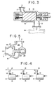
- More specifically, as illustrated in Fig. 3, the existing screw type vacuum pump of this sort has a pair of intermeshed male and
female screw rotors 19 rotatably accommodated in acasing 18 which is provided with asuction port 13 on one side and adischarge port 17 on the other side, the rotors being rotationally driven in one direction, for example, by arotor shaft 20 which is extended through and out of thecasing 18 on the side of thesuction port 13. As indicated by an arrow of solid line in the same figure, a gas is taken into thepump casing 15 through thesuction port 13 and discharged through thedischarge port 17. However, should a suction force acting in a direction inverse to the solid line arrow occur at thesuction port 13 as indicated by an arrow of broken line, gas would flow in through the discharge port in the direction of the broken line arrow, rotating the rotors in reverse directions. This happens when avacuum tank 26 is directly connected to thesuction port 13 of thevacuum pump 12 as shown by imaginary line in Fig. 3, namely, the rotors are rotated in reverse directions when the operation of thepump 12 is stopped, due to a pressure difference between thevacuum tank 26 and the atmosphere, permitting air to flow into thetank 26. - The time of reverse rotation on such an occasion as determined depending upon the size of and the pressure in the
tank 26. This phenomenon of reverse rotation imposes adverse effects on bearings of the rotors and other associated parts. Namely, since the lubricant oil is supplied to the bearings and synchronous gears by an oil pump which is generally driven in synchronism with the drive source of the vacuum pump, the oil pump is stopped as soon as the vacuum pump comes to a stop. - Therefore, the rotors are rotated in reverse directions without supplying the lubricant oil to the bearings and other parts which need lubrication, imposing adverse effects thereon.
- The reverse rotor rotation phenomenon also occurs in the following circumstances.
- In a case where a plural number of screw
type vacuum pumps 12 have their suction ports connected to a common suction passage 11 throughrespective branch passages 14 as shown in Fig. 4, if onepump 15 in the rightmost position in the figure alone is stopped, its rotors are caused to rotate in reverse directions by the suction forces of the two other pumps which are in operation, as indicated by an arrow of broken line. The reverse rotation of the stoppedpump 15 might lead to a breakdown since it is put in operation without supply of lubricant oil to its bearings, synchronous gears and other parts which need lubrication. - In order to prevent such a situation resulting from reverse rotation of a
pump 15, it is the usual practice to install acheck valve 16 in eachbranch passage 14. - In case the
check valve 16 is a commercial product, it is generally constituted by, as shown in Fig. 5, avalve casing 23 internally providing agas flow space 22 with avalve seat 21, avalve body 25 intimately seatable on thevalve seat 21, and acoil spring 25 constantly urging thevalve body 24 toward thevalve seat 21 for intimate engagement therewith. In this case, when a suction force exists at thesuction port 13, namely, when a suction force acts in the direction of port x in the drawing, the valve is opened and gas flows from port y to port x. Conversely, when a suction force comes fromother pump 15, namely, when a suction force acts in the direction of port y, thevalve body 24 is held in intimate contact with thevalve seat 21, thereby closing the valve to block reverse gas flows. - If the spring constant of the
coil spring 25 is small, however, thevacuum pump 12 with thecheck valve 16 of the above-mentioned construction suffers from a time dealy in closing the valve when the suction force is reversed toward the port y, failing to completely preclude the reverse rotation of thepump 15. - On the contrary, when the spring constant is increased, there arises a problem that the
valve body 24 is repeatedly hit against thevalve body 21 due to the low density of influent gas in the vacuum device, causing the hunting phenomenon in which the valve is opened and closed repeatedly. - It is an object of the present invention to overcome the above-mentioned problems of the conventional devices, more particularly, to provide a screw type vacuum pump which is adapted to open and close the check valve in a prompt and secure manner.
- In accordance with the present invention, this object is achieved by provision of a screw type vacuum pump construction including a pair of intermeshed male and female rotors, a pump casing having a suction port and a discharge port on the opposite sides thereof, an overdrive mechanism adapted to increase the speed of the rotational driving force of a motor before transmission to a rotor, an overdrive casing also serving as an oil tank, oil circulating passages passing through lubricating points of the pump casing, overdrive gears, oil tank, oil pump and oil cooler, and a valve provided in a passage leading to the suction port of the pump casing, characterized in that the check valve comprises: a valve casing internally providing a gas flow space with a valve seat in an intermediate portion thereof and a cylinder space; a valve body holding the two spaces in shielded state from each other through a suitable seal means and passed through a partition wall between the two sapces to disengageably engage a valve portion on the side of the gas flow space intimately with the valve seat, the valve body having a piston slidably fitted in the cylinder space to define an oil chamber on the side of the gas flow space and an atmospheric chamber on the opposite side in communication with the atmospher; a spring means constantly biasing the valve body into intimate contact with the valve seat; and bypass passages for communicating the oil chamber with the outlet of of the oil cooler and the oil tank through a three-way change-over valve adapted to switch the bypass passages to communicate the oil chamber with either the outlet of the oil cooler or the oil tank.
- This check valve arrangement according to the invention uses hydraulic pressure for opening the check valve, using a spring means only at the time of closing the valve, so that it gives a broad freedom in selection of the spring constant of the spring means and can close the valve promptly and open same in a secure manner.
- The above and other objects, features and advantages of the invention will become apparent from the following description and the appended claims, taken in conjunction with the accompanying drawings which show by way of example a preferred embodiment of the invention.
- In the accompanying drawings:
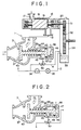
- Fig. 1 is a diagrammatic sectional view of a screw type vacuum pump according to the present invention;
- Fig. 2 is a diagrammatic sectional view of the check valve portion in operation of the pump of Fig. 1;
- Fig. 3 is a diagrammatic sectional view of the pump assembly of the screw type vacuum pump;
- Fig. 4 is a diagrammatic view of a gas system of vacuum equipments using conventional screw type vacuum pumps; and
- Fig. 5 is a diagrammatic sectional view of a conventional check valve.
- Now, the invention is described more particularly by way of a preferred embodiment shown in the drawings.
- Referring to Fig. 1, there is illustrated a screw type vacuum pump 1 embodying the present invention, which includes a screw
type pump casing 15, substantially same as the one shown in Fig. 3, anoil circulating passage 2, acheck valve 3 and abypass passage 4. The component parts which are common to Fig. 3 are designated by common reference numerals. - Fig. 1 further shows a
pump casing portion 15 which is omitted in Fig. 3. The driving force of a motor, which is not shown, is transmitted to ascrew rotor 19 through intermeshed small andlarge gears oil reservoir 33 in a lower portion thereof to serve also as an oil tank. - The
oil circulating passage 2 consists of flow passages leading from theoil reservoir 33 to lubricant supply points for bearings, shaft sealers, synchronous gears and other parts in thepump casing 15 through theoil pump 35 andoil cooler 36, and thereafter returning again to theoil reservoir 33, thereby circulating the oil in theoil reservoir 33. - In this embodiment, the
check valve 3 is composed of avalve casing 37, a valve body 38 and acoil spring 39. Thevalve casing 37 is internally provided with agas flow space 41 which has avalve seat 40 in an intermediate portion thereof, acylinder space 42, and a partition means provided between the just-mentioned twospaces - The valve body 38 is fitted in the partition means through an O-ring to shield the two spaces from each other. The end portion of the valve body 38 on the side of the
gas flow space 41 is configured to engage intimately with thevalve seat 40, and apiston 47 is provided on the valve body on the side of the cylinder space in such a manner as to partition the cylinder space into anoil chamber 45 on the side of the gas flow space and anatmospheric chamber 46 on the opposite side in communication with the atmosphere. - More specifically, the
oil chamber 45 is supplied with oil from theoil reservoir 33 which will be described hereinlater, while theatmospheric chamber 46 is provided with aport 48 which comunicates with the atmosphere, the twochambers piston 47. - The
coil spring 39 is arranged to constantly urge the valve body 38 into intimate contact with thevalve seat 40. - The
bypass passage 4 includes conduits which communicate theoil chamber 45 with the output of theoil cooler 36 and theoil reservoir 39 through a three-way change-overvalve 50 with ports a, b and c, switching the conduits to communicate theoil chamber 45 either to the outlet of theoil cooler 36 or theoil reservoir 33. - When the ports b-c are in communication, the
oil chamber 45 is communicated with theoil reservoir 33 which is under atmospheric pressure, so that the oil in theoil chamber 45 flows out toward theoil reservoir 33 and the valve body 38 is moved leftward in Fig. 1 by the action of thecoil spring 39 to hold the valve in closed state. - On the contrary, when the ports a-b are in communication with each other, the oil in the
oil circulating passage 2 is led into theoil chamber 45 as shown in Fig. 2, moving the valve body 38 rightward in the same figure against the action of thespring 39 to hold the valve in open state. - In this manner, the valve is opened by hydraulic pressure, and therefore there is a great freedom in selecting the force of the coil spring to be used for closeing the valve.
- The vacuum pump with above-described arrangement operates in the manner as follows.
- When stopping the vacuum pump 1, the
oil pump 35 is stopped, holding the ports b-c of the three-way change-overvalve 50 in communication with each other. Consequently, the oil in theoil chamber 45 is drained to theoil reservoir 33, whereupon the valve body 38 is moved into intimate contact with thevalve seat 40 by the action of thecoil spring 39 to close the valve. - On the other hand, while the. vacuum pump 1 is operation, the
oil pump 35 is put in operation, holding the ports a-b of the three-way change-overvalve 50 in communication with each other. As a result, oil pressure is developed in theoil chamber 45 thereby moving the valve body 38 rightward to open the valve, thereby securing the gas flow passage. - According to the present invention, as clear from the foregoing description, the check valve constructed includes: a valve casing internally providing a gas flow space with a valve seat in an intermediate portion thereof and a cylinder space; a valve body holding the two spaces in shielded state from each other through a suitable seal means and passed through a partition wall between the two spaces to disengageably engage a valve portion on the side of the gas flow space intimately with the valve seat, the valve body having a piston slidably partitioning the cylinder space to provide an oil chamber on the side of the gas flow space and an atmospheric chamber on the opposite side in communication with the atmosphere; a spring means constantly urging the valve body into intimate contact with tbe valve seat; and bypass passages for communicating the oil chamber with the outlet of the oil cooler and the oil tank through a three-way change-over valve adapted to switch the bypass passages to communicate the oil chamber with either the outlet of the coil cooler or the oil tank.
- Thus, the present invention permits to select a spring with a suitable spring constant for seating the valve body on the valve seat securely and promptly to prevent reverse gas flows, and to open the valve securely by hydraulic pressure to secure the gas flow passage without the hunting phenomenon.
- Described herein a screw type vacuum pump having in a passage leading to its suction port a check valve which is adapted to open the valve securely by hydraulic pressure to establish the gas flow passage without the hunting phenomenon, while permitting to select a spring with a suitable spring constant for seating the valve body 'on the valve seat securely and promptly to prevent reverse gas flows.
Claims (3)
a valve casing internally providing a gas flow space with a valve seat in an intermediate portion thereof and a cylinder space;
a valve body holding said two spaces in shielded state from each other through a suitable seal means and passed through a partition wall between said two spaces to disengageably engage a valve portion on the side of said gas flow space intimately with said valve seat, said valve body having a piston slidably fitted in said cylinder space and partitioning same to form an oil chamber on the side of said gas flow space and an atmospheric chamber on the opposite side in communication with the atmosphere;
a spring means constantly biasing said valve body into intimate contact with said valve seat; and
bypass passages for communicating said oil chamber with the outlet of said oil cooler and said oil tank through a three-way change-over valve adapted to switch said bypass passages to communicate said oil chamber with either the outlet of said oil cooler or said oil tank.
Applications Claiming Priority (2)
| Application Number | Priority Date | Filing Date | Title |
|---|---|---|---|
| JP63206904A JPH0255892A (en) | 1988-08-19 | 1988-08-19 | Screw-type vacuum pump |
| JP206904/88 | 1988-08-19 |
Publications (3)
| Publication Number | Publication Date |
|---|---|
| EP0355260A2 true EP0355260A2 (en) | 1990-02-28 |
| EP0355260A3 EP0355260A3 (en) | 1990-05-30 |
| EP0355260B1 EP0355260B1 (en) | 1993-01-07 |
Family
ID=16530992
Family Applications (1)
| Application Number | Title | Priority Date | Filing Date |
|---|---|---|---|
| EP89106927A Expired - Lifetime EP0355260B1 (en) | 1988-08-19 | 1989-04-18 | Screw type vacuum pump |
Country Status (4)
| Country | Link |
|---|---|
| US (1) | US5018947A (en) |
| EP (1) | EP0355260B1 (en) |
| JP (1) | JPH0255892A (en) |
| DE (1) | DE68904263T2 (en) |
Cited By (1)
| Publication number | Priority date | Publication date | Assignee | Title |
|---|---|---|---|---|
| EP0597732A1 (en) | 1992-11-13 | 1994-05-18 | The BOC Group plc | Vacuum pump with inlet oil-controlled valve |
Families Citing this family (8)
| Publication number | Priority date | Publication date | Assignee | Title |
|---|---|---|---|---|
| DE4325283A1 (en) * | 1993-07-28 | 1995-02-02 | Leybold Ag | Valve system controllable as a function of operation for a vacuum pump |
| US5456582A (en) * | 1993-12-23 | 1995-10-10 | Sullair Corporation | Compressor inlet valve with improved response time |
| US5388968A (en) * | 1994-01-12 | 1995-02-14 | Ingersoll-Rand Company | Compressor inlet valve |
| AT403948B (en) * | 1994-07-29 | 1998-06-25 | Hoerbiger Ventilwerke Ag | INTAKE CONTROL VALVE FOR ROTATIONAL COMPRESSORS |
| US5540558A (en) * | 1995-08-07 | 1996-07-30 | Ingersoll-Rand Company | Apparatus and method for electronically controlling inlet flow and preventing backflow in a compressor |
| DE19625565C2 (en) * | 1996-06-26 | 1998-07-23 | Bosch Gmbh Robert | Fuel feed pump for a fuel injection pump for internal combustion engines |
| CN102725532B (en) * | 2010-01-29 | 2015-09-23 | Ulvac机工株式会社 | Pump |
| DE102011084811B3 (en) | 2011-10-19 | 2012-12-27 | Kaeser Kompressoren Ag | Gas inlet valve for a compressor, compressor with such a gas inlet valve and method for operating a compressor with such a gas inlet valve |
Family Cites Families (7)
| Publication number | Priority date | Publication date | Assignee | Title |
|---|---|---|---|---|
| US3687017A (en) * | 1970-12-08 | 1972-08-29 | Westinghouse Electric Corp | Servo-actuator mechanism |
| DE3142832A1 (en) * | 1981-10-29 | 1983-05-11 | Boise Cascade Corp., 83728 Boise, Id. | "DEVICE FOR PRODUCING A CONTINUOUS CORRUGATED CARDBOARD RAIL" |
| DD221508B3 (en) * | 1984-02-29 | 1992-12-24 | Zwetko Zwetkow | BREAKING VALVE FOR VACUUM PUMPS |
| JPS60249690A (en) * | 1984-05-21 | 1985-12-10 | ゼネラル シグナル コーポレーシヨン | rotating piston vacuum pump |
| CA1279856C (en) * | 1985-10-09 | 1991-02-05 | Akira Suzuki | Oilless rotary type compressor system |
| DE8533839U1 (en) * | 1985-12-02 | 1987-04-09 | Barmag AG, 5630 Remscheid | Vacuum pump |
| JP2511870B2 (en) * | 1986-03-20 | 1996-07-03 | 株式会社日立製作所 | Screen-vacuum pump device |
-
1988
- 1988-08-19 JP JP63206904A patent/JPH0255892A/en active Granted
-
1989
- 1989-03-30 US US07/330,696 patent/US5018947A/en not_active Expired - Fee Related
- 1989-04-18 EP EP89106927A patent/EP0355260B1/en not_active Expired - Lifetime
- 1989-04-18 DE DE8989106927T patent/DE68904263T2/en not_active Expired - Fee Related
Cited By (2)
| Publication number | Priority date | Publication date | Assignee | Title |
|---|---|---|---|---|
| EP0597732A1 (en) | 1992-11-13 | 1994-05-18 | The BOC Group plc | Vacuum pump with inlet oil-controlled valve |
| US5419689A (en) * | 1992-11-13 | 1995-05-30 | The Boc Group Plc | Vacuum pump having oil-actuated inlet valve |
Also Published As
| Publication number | Publication date |
|---|---|
| JPH0522079B2 (en) | 1993-03-26 |
| EP0355260A3 (en) | 1990-05-30 |
| JPH0255892A (en) | 1990-02-26 |
| DE68904263D1 (en) | 1993-02-18 |
| US5018947A (en) | 1991-05-28 |
| DE68904263T2 (en) | 1993-05-06 |
| EP0355260B1 (en) | 1993-01-07 |
Similar Documents
| Publication | Publication Date | Title |
|---|---|---|
| EP0991865B1 (en) | Multiple pump control arrangement | |
| EP0128446B1 (en) | Selectively controlled dual delivery pump, particularly for motor vehicle application | |
| US4388048A (en) | Stepping type unloading system for helical screw rotary compressor | |
| JPS62261693A (en) | Selective type delivery pump | |
| US4551080A (en) | Variable displacement sliding vane pump/hydraulic motor | |
| US5018947A (en) | Screw type vacuum pump | |
| US7086366B1 (en) | Energy efficient fluid pump | |
| CA2254336A1 (en) | Fail-safe electric hydraulic actuator | |
| US4538966A (en) | Oil pump assembly | |
| US5184947A (en) | Fully variable output hydraulic gear pump having an axially translatable gear | |
| JPH09511319A (en) | Continuously variable hydraulic transmission with transmission ratio controller actuating components built into the output shaft | |
| US3873252A (en) | Gear pump and motor | |
| CA2065165A1 (en) | Gear pump having internal bypass valve | |
| US4746276A (en) | Gear pump having conditional dry valve closure structure | |
| CN218347672U (en) | Hydraulic workstation and inspection robot | |
| US5618165A (en) | Variable displacement and constant pressure pump | |
| US4222715A (en) | Device for delivery control in a rotary piston compressor | |
| SE502257C2 (en) | Plungeventil | |
| US4718378A (en) | Transmission coupling | |
| JP4326347B2 (en) | Stepless transmission | |
| US3873241A (en) | Variable output gear pump and motor | |
| AU3159795A (en) | Outlet pressure control for internal gear pump | |
| EP0162434A2 (en) | Antisuckback device for rotary piston pumps | |
| US4191018A (en) | Fluid transmission | |
| US5236317A (en) | Gear pump valving system |
Legal Events
| Date | Code | Title | Description |
|---|---|---|---|
| PUAI | Public reference made under article 153(3) epc to a published international application that has entered the european phase |
Free format text: ORIGINAL CODE: 0009012 |
|
| 17P | Request for examination filed |
Effective date: 19890418 |
|
| AK | Designated contracting states |
Kind code of ref document: A2 Designated state(s): DE FR GB |
|
| PUAL | Search report despatched |
Free format text: ORIGINAL CODE: 0009013 |
|
| AK | Designated contracting states |
Kind code of ref document: A3 Designated state(s): DE FR GB |
|
| 17Q | First examination report despatched |
Effective date: 19910130 |
|
| GRAA | (expected) grant |
Free format text: ORIGINAL CODE: 0009210 |
|
| AK | Designated contracting states |
Kind code of ref document: B1 Designated state(s): DE FR GB |
|
| ET | Fr: translation filed | ||
| REF | Corresponds to: |
Ref document number: 68904263 Country of ref document: DE Date of ref document: 19930218 |
|
| PLBE | No opposition filed within time limit |
Free format text: ORIGINAL CODE: 0009261 |
|
| STAA | Information on the status of an ep patent application or granted ep patent |
Free format text: STATUS: NO OPPOSITION FILED WITHIN TIME LIMIT |
|
| 26N | No opposition filed | ||
| PGFP | Annual fee paid to national office [announced via postgrant information from national office to epo] |
Ref country code: GB Payment date: 19980409 Year of fee payment: 10 Ref country code: FR Payment date: 19980409 Year of fee payment: 10 |
|
| PGFP | Annual fee paid to national office [announced via postgrant information from national office to epo] |
Ref country code: DE Payment date: 19980424 Year of fee payment: 10 |
|
| PG25 | Lapsed in a contracting state [announced via postgrant information from national office to epo] |
Ref country code: GB Free format text: LAPSE BECAUSE OF NON-PAYMENT OF DUE FEES Effective date: 19990418 |
|
| GBPC | Gb: european patent ceased through non-payment of renewal fee |
Effective date: 19990418 |
|
| PG25 | Lapsed in a contracting state [announced via postgrant information from national office to epo] |
Ref country code: FR Free format text: LAPSE BECAUSE OF NON-PAYMENT OF DUE FEES Effective date: 19991231 |
|
| REG | Reference to a national code |
Ref country code: FR Ref legal event code: ST |
|
| PG25 | Lapsed in a contracting state [announced via postgrant information from national office to epo] |
Ref country code: DE Free format text: LAPSE BECAUSE OF NON-PAYMENT OF DUE FEES Effective date: 20000201 |