EP0355264A2 - Dispositif pour le réglage d'un compteur réglable - Google Patents
Dispositif pour le réglage d'un compteur réglable Download PDFInfo
- Publication number
- EP0355264A2 EP0355264A2 EP89107425A EP89107425A EP0355264A2 EP 0355264 A2 EP0355264 A2 EP 0355264A2 EP 89107425 A EP89107425 A EP 89107425A EP 89107425 A EP89107425 A EP 89107425A EP 0355264 A2 EP0355264 A2 EP 0355264A2
- Authority
- EP
- European Patent Office
- Prior art keywords
- counter
- stepper motor
- coil
- shaft
- drive pulley
- Prior art date
- Legal status (The legal status is an assumption and is not a legal conclusion. Google has not performed a legal analysis and makes no representation as to the accuracy of the status listed.)
- Granted
Links
Images



Classifications
-
- G—PHYSICS
- G06—COMPUTING OR CALCULATING; COUNTING
- G06M—COUNTING MECHANISMS; COUNTING OF OBJECTS NOT OTHERWISE PROVIDED FOR
- G06M1/00—Design features of general application
- G06M1/28—Design features of general application for zeroising or setting to a particular value
- G06M1/283—Design features of general application for zeroising or setting to a particular value with drums
-
- H—ELECTRICITY
- H02—GENERATION; CONVERSION OR DISTRIBUTION OF ELECTRIC POWER
- H02K—DYNAMO-ELECTRIC MACHINES
- H02K7/00—Arrangements for handling mechanical energy structurally associated with dynamo-electric machines, e.g. structural association with mechanical driving motors or auxiliary dynamo-electric machines
- H02K7/10—Structural association with clutches, brakes, gears, pulleys or mechanical starters
Definitions
- the invention relates to a cross-wound rotating magnet arrangement according to the preamble of claim 1.
- a known cross-coil rotating magnet arrangement is specially designed as a motor for driving a clockwork (DE-OS 34 19 100).
- a rotatably mounted rotor has diametrically opposed permanent magnet poles.
- a multi-phase coil arrangement serves to generate a magnetic field deflecting the rotor as a function of control signals which are applied to coils of the coil arrangement.
- the coil arrangement has a plurality of coils, which are arranged at the same angular distance from one another and surround the rotor and can be controlled with sine voltages offset by a specific phase shift.
- the coil arrangement consists of two coils arranged at right angles to one another, which are fed with two sine voltages offset by 90 °.
- the axis of rotation or shaft can represent the second wave or the minute wave of the clockwork.
- a minute hand is attached to one end of the axis of rotation, that can be moved over a dial.
- An hour wheel which has an hour tube enclosing the axis of rotation, is driven via a drive pinion arranged on the axis of rotation and a change wheel.
- This motor which is designed to drive a clockwork, has a drive pinion, change gear and hour wheel, and an hour tube is not intended for the adjustment of a resettable mechanical counter. For this purpose, it cannot easily form a compact structural unit, in particular with a roller counter. In addition, a reset device for the counter is missing.
- a measuring mechanism is used to adjust a pointer, which is connected via a converter to a transmitter generating a pulse proportional to the measured variable (De -OS 27 30 699).
- a stepper motor running backwards and forwards serves as the measuring mechanism. This is fed with a direction-weighted pulse sequence which is generated from counted values formed during successive defined time intervals as a function of the measured variable and which, when compared with one another, result in a sign-weighted difference number.
- the stepper motor which is set in accordance with this difference, is coupled to a pointer mechanism via a gear.
- this stepper motor is not easily suitable for adjusting a resettable mechanical counter, in particular a roller counter for odometer counting, since resetting by the driving pinion of the stepper motor, if it works at all, would take at least too long when it comes to the roles of the higher digits .
- Odometers or other roller counters are usually driven with a stepper motor, which is only in one Direction is running.
- the counter is reset either manually, using a lifting magnet or another motor.
- the reset takes place via a so-called zero-setting axis, which in turn can reset the individual rollers of a roller counter by means of heart curves by briefly rotating a maximum of 180 °.
- a separate drive with a reset mechanism is required for this reset.
- the object of the present invention is to achieve a rapid resetting of a mechanical counter, in particular a roller counter, using only a single stepping motor.
- the stepper motor, a gearbox coupled to drive the counter, and the reset device are intended to form a compact unit.
- stepper motor By designing the stepper motor with a split bobbin, on the front outside of which the gear enclosed in an intermediate body can be attached or clipped, into which a pinion engages a groove protruding from the bobbin, a space-saving unit is created to which the additional , According to the invention provided one-way clutch can be attached while maintaining the compact structure, as well as the counter, in particular roller counter, with the associated reset device.
- the stepper motor can, in addition to the usual function for adjusting the counter when counting up, also reset the counter via a zeroing axis or other reset device by using a with the Gear-coupled element, in particular a cam disc, acts on the resetting device when the stepping motor rotates backwards, while this element, in particular the cam disc, acts on the stepping motor when the stepping motor rotates forward when the counter is adjusted in the sense of counting up.
- the freewheeling enables the functional separation - counting up and resetting - to take place without further control measures solely depending on the direction of rotation of the stepper motor.
- the entire facility can be implemented with only a few uncomplicated parts and thus in a manner which is favorable for production; it is low-wear and robust.
- a particularly compact structure of the device for adjusting a roller counter with space-saving internal toothing is made possible according to claim 2 by the development that the output shaft of the transmission projecting from the intermediate body or the gear on its side facing away from the bobbin is arranged eccentrically.
- the roller counter with its main axis can be arranged coaxially with the motor shaft and the main axis of the gearbox to form a preferably approximately cylindrical spatial shape, in which the individual components of the device - motor, gearbox, roller counter - follow one another practically without axial gaps.
- the pinion on the output shaft of the transmission engages in an internal toothing of a first drive wheel belonging to the roller counter in a space-saving and protected manner.
- the device is further advantageously designed in detail with the features specified in claim 3. Due to the cam disk for resetting the zero-setting axis or another resetting device and the one-way clutch enclosed by the cam disk, only a relatively slight axial extension of a normal first drive wheel occurs. This applies in particular if the device is designed according to claim 4.
- the one-way clutch can be implemented in various ways: a ball as a movable entrainment element according to claim 4 is particularly low-friction. With the roller as a movable entrainment element according to claim 6, larger forces can also be transmitted with relatively low friction. A wedge as a movable driving element according to claim 7 is particularly robust.
- the one-way clutch can also be constructed according to claim 8 with a tooth lock which comprises a pawl and locking teeth which come into engagement therewith.
- the tooth lock can be conventional; a special construction is not necessary.
- the coil body is essentially in a cross-sectional plane, i.e. divided perpendicular to the shaft installed between the two parts of the coil body.
- one of the bearings of the shaft is also expediently formed from each of the two parts of the coil former.
- the rotor is arranged between the two bearings in the cylindrical interior of the bobbin.
- Two windings are applied to the bobbin as a stator rotated 90 ° relative to each other so that the conductors are parallel to the shaft between two webs adjacent along the circumference.
- the stator of the stepper motor is advantageously designed according to claim 11.
- a detent effect or a detent torque is thus exerted on the rotor without pronounced poles as a result of the magnetic yoke, which thus determines defined positions of the rotor.
- the control can take place with short pulses which mean a low average current consumption. It is therefore not necessary for the stepper motor to be supplied with sinusoidal voltages.
- damping of the rotor movement is achieved with a shielding ring made of unannealed, inferior iron, which has a residual coercive field strength of approx. 5 ⁇ e.
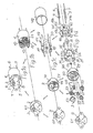
- a stepping motor with a clipped-on transmission in an intermediate body 2 can be seen from FIG.
- the longitudinal dimensions of the stepper motor and the intermediate body result in the relatively small height h of the arrangement, which is decisive for the installation.
- an output shaft 3 of the transmission can be seen, which projects eccentrically from the intermediate body 2 to the front.
- This output shaft is shown in Fig. 1a in an inverted position - upside down - to the position in Fig. 8.
- the front outside of this arrangement is designated 8; it is formed by a circuit board 9 which closes off the intermediate body at the front.
- the outside of the stepper motor itself is covered in Fig. 1a.
- the intermediate body which contains the transmission, is removed from the stepper motor, so that two coils 10 and 11 arranged at an angular distance of 90 ° to one another can be seen in the stepper motor, which together form a cheese or a two-phase winding .
- A protrudes from a front outside 12 of the stepper motor pinion 13 mounted on a shaft, which, as described below, can be inserted into the transmission in the intermediate body such that it engages with a gearwheel in the transmission.
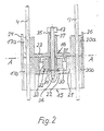
- a bobbin generally designated 14 which is essentially divided in a cross-sectional plane A-A - see FIG. 1 - consists of two bobbin parts 15 and 16.
- the coil former 15 is cylindrical in shape on the inside and has four webs 17 - 20, the outer sides of which are cylindrically curved. According to FIG. 1d, the webs are each composed of a front web section 17a, 18a, 20a and a rear web section 17b, 18b, 19b, 20b, which have the same cross-sectional shapes. The webs are shaped so that they form chambers between them for receiving the two coils 10 and 11.
- the rear web sections 17b, 18b, 19b, 20b converge to form a cylindrical ring 21 which is closed on the inside by an intermediate wall 22 - see FIG. 2.
- the front web sections 17a, 18a, 19a, 20a are formed on a front wall 23.
- Tongue-like clips 24, 25, 26, 27 protrude from the front web sections 17a, 18a, 19a, 20a, which are provided for positive and non-positive engagement in corresponding recesses in the intermediate body 2 in order to hold the latter in a clamped manner.
- the recesses 28 and 29 can be seen from this in FIGS. 1c and 1d.
- the recesses are groove-shaped and, because they are distributed equidistantly over the circumference of the intermediate body, also serve for centering.
- the cylindrical ring 21 of the bobbin part 15 includes a likewise cylindrical interior 30, which is forwardly or in FIG. 2 above by a cylindrical one Approach 31 provided front wall 23 of the bobbin part 16 is completed.
- a rotor which is generally designated 32, is mounted in the cylindrical interior 30.
- the rotor consists essentially of a permanent magnet 33 which is magnetized to form diametrically opposite poles.
- the rotor is attached to a shaft 35 via a hub 34.
- the shaft is rotatably supported in one bearing 36 and 37 in each of the two coil former parts 15 and 16, respectively.
- a pinion 13 is fixed on a front end of the shaft protruding from the coil body part 16.
- plug pins 4-7 can be plugged in, which essentially serve to fasten the arrangement, for example, to printed circuit boards.
- a cylindrical shielding ring 48 made of ferromagnetic material can be pushed onto the webs on the outside, the residual coercive field strength for damping the stepping motor is approximately 5 eyelet and which can additionally consist of unannealed, inferior iron.
- a ferromagnetic material with a high residual coercive field strength of, for example, 50-100 ⁇ e is used.
- 1c and 1d further details of the gear provided in the intermediate body. It is essentially formed by the gear wheels 49-53 and the pinions 54-57 connected to the gear wheels 49, 50, 51, 52, the gear wheels and pinions meshing in pairs.
- the pinion 13 on the shaft 35 can by ei Ne opening 58 are inserted into the intermediate body so that it comes into engagement with the first gear 49.
- the gear 53 on the output shaft of the transmission is connected to the eccentrically arranged output shaft 3.
- FIG. 3 shows how the gearwheels and pinions are mounted in the front board 9 and a wall 62 corresponding to it on the rear. 3, the connection pins extend - the connection pins 4 and 7 can be seen - through relatively large bores 63 - 66 in the circuit board 9 and wall 62, so that the position of the connection pins only through the bores in the coil body parts 15, 16 is determined.
- the bearing 36 is designed both in Fig. 2 and in Fig. 3 so that it can also absorb axial forces.
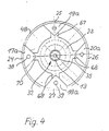
- FIG. 4 shows a view of the front width of the stepper motor without an intermediate body attached: the webs or web sections 17a, 18a, 19a, 20a arranged with the protruding clips 24-27 arranged equidistantly along the circumference of the essentially cylindrical coil body can be seen whose rear end faces the shielding ring 48 pushed onto the bobbin.
- the web sections merge into the front wall 23 at the points 67-70.
- the central shaft 35 to which the pinion 13 is attached can also be seen.
- the rotor 32 covered by the front wall 23 is only indicated with a broken line.
- the electrical control of the stepper motor can be largely conventional at least for the forward run.
- a designated 71 Neter encoder generates pulses that are proportional to the travel increments of a vehicle.
- the pulses for the forward direction after pulse shaping can be transmitted to a control logic 74 for the stepper motor, in which the coils 10 and 11 - see FIG. 1b - of the stator supplying voltages are generated which have a curve shape, which cause the rotor to rotate.
- the processing logic controls the control logic in such a way that a voltage curve which causes the rotor to move forward is generated in the control logic for pulses which are emitted by the transmitter 71. If, on the other hand, a reset signal is fed into a reset input 59 of the processing logic 74, the processing logic generates a predetermined number of pulses (pulse packet), which influences the control logic 74 to emit a voltage curve which causes a defined backward movement of the rotor.
- the pulse package ensures an automatic return within less than a second.
- the stepper motor 73 and the transmission with one-way clutch 75 are shown schematically.
- the transmission adjusts the rollers of the roller counter to count up in the forward direction of rotation, a cam disk 78 assigned to a zeroing lever 77 of the roller counter being uncoupled. With the reverse direction of rotation of the stepping motor 73 and the clutch 78 closed, on the other hand, the reset takes place automatically via the zeroing lever 77.
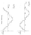
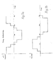
- voltages U are generated for the coils 10 and 11 in the control logic, which here cause the rotor to rotate forward.
- the voltages represent a step-wise approximated cosine function for the coil 10 and an approximated sinusoidal curve shape for the coil 11 as a function of the count value ⁇ Soll to be displayed.
- These curve shapes of the voltages run through a full period as a time-dependent predetermined amplitude sequence for a run of the rotor of 360 °.
- the amplitude sequences can also be interpreted as phase-shifted, approximately sinusoidal or cosine-shaped voltage profiles.
- the step-by-step approximation of the sine shape and cosine shape can be easily implemented with digital components, for example at a fixed clock frequency via a controlled duty cycle. Since the roller counter is adjusted by the stepper motor via a gear, which is contained in the intermediate body, a rough step of the approximation is sufficient.
- curve shapes approximated tangentially in the form of voltages for the coils 10 and 11 are formed in the control logic 74, which allow even less effort to be generated than the above-mentioned sinusoidal and cosine curve shapes.
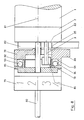
- FIG. 8 the device for adjusting a resettable roller counter with a first drive wheel is shown in longitudinal section in a larger representation.
- the number rollers are rotatable about an axis 80 which is aligned with a main axis of the transmission and the motor. This main axis is indicated by a dash-dotted line.
- a mounting bracket 82 is used to fasten the device, into which, for example, the connecting pins which cannot be seen in FIG. 8 - see connecting pins 4 - 7 in FIG. 1a - can extend.
- the motor 1 and the gearbox clipped onto it are arranged to the right of the bearing block.
- the output shaft 3 of the transmission projects with the pinion 13 into an internal toothing 84 of a drive pulley 85, which forms part of a first drive wheel 86 and as such is connected to the first number roll 79.
- the first drive wheel 86 includes a cam disk 78, which is also mounted on the axle 80.
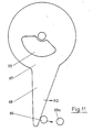
- the cam plate which is essentially cylindrical on the outside, has a cam 88 there, which can strike against this in order to adjust a zeroing lever 89 - see FIG. 11.
- the cam disk encompasses a cylindrical inner section 90 of the first drive disk, from which wedge spaces 91, 92 are formed, the shape of which can be seen in detail from the top view in FIG. 9.
- the wedge shape is formed on the outside by the cylindrical inner shape of the overlapping section of the cam disk 78.
- the one-way clutch is completed by a ball 93 or 94 in each of the two wedge spaces 91, 92. It is also remarkable in the illustration according to FIG. 8 that the motor, the gear, the roller counter with the number roller 93 and the first drive wheel 86 form a compact, essentially cylindrical unit.
- the motor receives stator voltages as a result of a pulse packet causing the reset, which causes rotation in the direction R2 of the pinion 38, the balls 93, 94 move into the tapering part of the wedge spaces 91, 92 and wedge between the one shown in FIG. 9 horizontal section of the wedge space on the inner section 90 of the first drive pulley and the cylindrical inner surface of the cam disk 78.
- the cam 88 in 11 also moves in the direction R2, abuts the zeroing lever 89 and takes it into the position shown at 89a, in which the zeroing lever has reset the roller counter by means not shown.
- FIG. 11 also shows an opening 95 in the form of a segment of a circle in the cam disk 78, through which the output shaft 3 of the transmission extends - see FIG. 8.
- the extent of the opening 95 in the circumferential direction is sufficient without letting the output shaft 3 hit, since a defined path is specified for the resetting by the pulse package mentioned.
- the zeroing lever 89 can reset the cam 88 to the position shown in FIG. 11 by means not shown, and a further counting process can begin.
- the arrangement shown is particularly suitable for resetting a trip meter in a motor vehicle.
- a variant of the one-way clutch is shown, which is designed here as a tooth lock.
- the first drive wheel is designated 96
- the pinion 13 engages in its internal teeth.
- the drive wheel is rotatable about the axis 80.
- the special feature of this drive wheel is that it is shaped on the outside as a ratchet wheel 97.
- a pawl 99 engages in the pawls of the pawl wheel and is pivotally mounted on the zeroing lever 89.
- the roller counter is reset by the same stepper motor, which also causes the roller counter to be incremented in one movement phase.
Landscapes
- Engineering & Computer Science (AREA)
- Physics & Mathematics (AREA)
- General Physics & Mathematics (AREA)
- Theoretical Computer Science (AREA)
- Power Engineering (AREA)
- Connection Of Motors, Electrical Generators, Mechanical Devices, And The Like (AREA)
- Control Of Stepping Motors (AREA)
- Transmission Devices (AREA)
Applications Claiming Priority (2)
| Application Number | Priority Date | Filing Date | Title |
|---|---|---|---|
| DE3828463 | 1988-08-22 | ||
| DE3828463A DE3828463A1 (de) | 1988-08-22 | 1988-08-22 | Einrichtung zur verstellung eines rueckstellbaren zaehlwerks |
Publications (3)
| Publication Number | Publication Date |
|---|---|
| EP0355264A2 true EP0355264A2 (fr) | 1990-02-28 |
| EP0355264A3 EP0355264A3 (fr) | 1993-03-17 |
| EP0355264B1 EP0355264B1 (fr) | 1994-09-21 |
Family
ID=6361344
Family Applications (1)
| Application Number | Title | Priority Date | Filing Date |
|---|---|---|---|
| EP89107425A Expired - Lifetime EP0355264B1 (fr) | 1988-08-22 | 1989-04-25 | Dispositif pour le réglage d'un compteur réglable |
Country Status (4)
| Country | Link |
|---|---|
| US (1) | US4973867A (fr) |
| EP (1) | EP0355264B1 (fr) |
| JP (1) | JPH0782531B2 (fr) |
| DE (2) | DE3828463A1 (fr) |
Cited By (3)
| Publication number | Priority date | Publication date | Assignee | Title |
|---|---|---|---|---|
| FR2737820A1 (fr) * | 1995-08-10 | 1997-02-14 | Elbi Int Spa | Moteur electrique synchrone, plus particulierement destine a des dispositifs programmateurs d'appareils electromenagers |
| EP0769841A3 (fr) * | 1995-10-20 | 1997-09-03 | Vdo Schindling | Moteur électrique et instrument de mesure, en particulier pour indicateurs de véhicules |
| CN101265968B (zh) * | 2008-04-23 | 2010-09-29 | 江苏南方轴承股份有限公司 | 自由式皮带轮 |
Families Citing this family (3)
| Publication number | Priority date | Publication date | Assignee | Title |
|---|---|---|---|---|
| DE4118374C2 (de) * | 1991-06-05 | 2000-08-10 | Mannesmann Vdo Ag | Elektrischer Schrittmotor für zwei Drehrichtungen |
| JP3418494B2 (ja) * | 1995-12-20 | 2003-06-23 | 株式会社ゼクセルヴァレオクライメートコントロール | モータアクチュエータの原点復帰機構 |
| TW533865U (en) * | 1997-06-10 | 2003-05-21 | Glaxo Group Ltd | Dispenser for dispensing medicament and actuation indicating device |
Family Cites Families (9)
| Publication number | Priority date | Publication date | Assignee | Title |
|---|---|---|---|---|
| DE1115062B (de) * | 1958-11-19 | 1961-10-12 | Rau Swf Autozubehoer | Zaehlwerk insbesondere fuer Kraftfahrzeug-Tachometer |
| DE1297917B (de) * | 1965-05-08 | 1969-06-19 | Siemens Ag | Einrichtung zur Steuerung des Abfrage- und Nullstellzyklus eines Zaehlwerkes |
| US4115713A (en) * | 1975-03-06 | 1978-09-19 | Motorola, Inc. | Rotor bias means for miniature watch motors or the like |
| US4009373A (en) * | 1975-12-11 | 1977-02-22 | Suntech, Inc. | Electro-mechanical counting register |
| DE2732364A1 (de) * | 1977-07-18 | 1979-02-08 | Quarz Zeit Ag | Elektrische uhr |
| NL8601422A (nl) * | 1986-06-03 | 1988-01-04 | Hugo Karel Krop | Stappenmotor en display voorzien van dergelijke stappenmotoren. |
| JPS63123187A (ja) * | 1986-11-12 | 1988-05-26 | Marugo:Kk | トリツプメ−タ−における零戻し装置 |
| US4930094A (en) * | 1988-07-11 | 1990-05-29 | Chrysler Corporation | Vehicle serial bus, mechanical instrument cluster odometer therefor |
| JP5428709B2 (ja) | 2009-09-29 | 2014-02-26 | 株式会社オートネットワーク技術研究所 | ヒューズホルダ |
-
1988
- 1988-08-22 DE DE3828463A patent/DE3828463A1/de not_active Withdrawn
-
1989
- 1989-04-25 EP EP89107425A patent/EP0355264B1/fr not_active Expired - Lifetime
- 1989-04-25 DE DE58908394T patent/DE58908394D1/de not_active Expired - Fee Related
- 1989-08-04 US US07/389,968 patent/US4973867A/en not_active Expired - Lifetime
- 1989-08-22 JP JP1214277A patent/JPH0782531B2/ja not_active Expired - Lifetime
Cited By (3)
| Publication number | Priority date | Publication date | Assignee | Title |
|---|---|---|---|---|
| FR2737820A1 (fr) * | 1995-08-10 | 1997-02-14 | Elbi Int Spa | Moteur electrique synchrone, plus particulierement destine a des dispositifs programmateurs d'appareils electromenagers |
| EP0769841A3 (fr) * | 1995-10-20 | 1997-09-03 | Vdo Schindling | Moteur électrique et instrument de mesure, en particulier pour indicateurs de véhicules |
| CN101265968B (zh) * | 2008-04-23 | 2010-09-29 | 江苏南方轴承股份有限公司 | 自由式皮带轮 |
Also Published As
| Publication number | Publication date |
|---|---|
| DE58908394D1 (de) | 1994-10-27 |
| EP0355264A3 (fr) | 1993-03-17 |
| US4973867A (en) | 1990-11-27 |
| JPH0782531B2 (ja) | 1995-09-06 |
| JPH02162485A (ja) | 1990-06-22 |
| DE3828463A1 (de) | 1990-03-01 |
| EP0355264B1 (fr) | 1994-09-21 |
Similar Documents
| Publication | Publication Date | Title |
|---|---|---|
| EP0617792B1 (fr) | Capteur de vitesse de rotation, notamment pour roues dentees | |
| DE2429492A1 (de) | Elektromagnetischer motor, insbesondere fuer impulszaehlwerke, und selbstanlaufender synchronmotor | |
| EP0671008B1 (fr) | Dispositif pour mesurer des mouvements rotatifs | |
| DE2515977C2 (de) | Meßwertgeber zum Erzeugen von Signalen in Abhängigkeit von der Winkelgeschwindigkeit eines rotierenden Körpers | |
| DE3937149A1 (de) | Kreuzspulmess- und -anzeigegeraet | |
| DE2239926A1 (de) | Stoerungsfreier elektromagnetischer aufnehmer | |
| EP0355264B1 (fr) | Dispositif pour le réglage d'un compteur réglable | |
| DE3344959A1 (de) | Impulsdrehzahlgeber | |
| DE102015202986A1 (de) | Kraftübertragungsgetriebe und Fahrzeuginstrument | |
| DE2838709C3 (de) | Antriebsvorrichtung für eine Uhr | |
| DE1548604B2 (fr) | ||
| DE2620859A1 (de) | Einrichtung zur rueckprallverhinderung fuer eine elektrische uhr | |
| DE2505330A1 (de) | Zaehl- und/oder zeitwerk | |
| DE2137800A1 (de) | Magnetische Aufnehmereinrichtung zum Messen der Winkelgeschwindigkeit oder Winkelstellung | |
| EP0355262B1 (fr) | Dispositif à bobine croisée et aimant rotatif | |
| DE3127141C2 (de) | "Wegstreckenzähler" | |
| EP0044905A1 (fr) | Transmission | |
| DE3049191C2 (fr) | ||
| EP0355263B1 (fr) | Moteur, en particulier pour entraîner une pièce d'horlogerie | |
| EP2192672A2 (fr) | Moteur électrique avec réducteur en plastique | |
| EP0684454A1 (fr) | Générateur inductif d'impulsions pour mesurer la vitesse de rotation d'un arbre tournant dans un carter | |
| DE2221532A1 (de) | Ein- oder mehrtouren-schaltklinkenkupplung | |
| DE19860266A1 (de) | Anzeige mit mindestens einem Zeiger, insbesondere für Uhren | |
| DE1805473A1 (de) | Elektromechanische Vorrichtung zur Impulszaehlung | |
| DE3149302C2 (fr) |
Legal Events
| Date | Code | Title | Description |
|---|---|---|---|
| PUAI | Public reference made under article 153(3) epc to a published international application that has entered the european phase |
Free format text: ORIGINAL CODE: 0009012 |
|
| AK | Designated contracting states |
Kind code of ref document: A2 Designated state(s): DE FR GB IT |
|
| PUAL | Search report despatched |
Free format text: ORIGINAL CODE: 0009013 |
|
| AK | Designated contracting states |
Kind code of ref document: A3 Designated state(s): DE FR GB IT |
|
| 17P | Request for examination filed |
Effective date: 19930203 |
|
| 17Q | First examination report despatched |
Effective date: 19931019 |
|
| GRAA | (expected) grant |
Free format text: ORIGINAL CODE: 0009210 |
|
| AK | Designated contracting states |
Kind code of ref document: B1 Designated state(s): DE FR GB IT |
|
| PG25 | Lapsed in a contracting state [announced via postgrant information from national office to epo] |
Ref country code: IT Free format text: LAPSE BECAUSE OF FAILURE TO SUBMIT A TRANSLATION OF THE DESCRIPTION OR TO PAY THE FEE WITHIN THE PRE;WARNING: LAPSES OF ITALIAN PATENTS WITH EFFECTIVE DATE BEFORE 2007 MAY HAVE OCCURRED AT ANY TIME BEFORE 2007. THE CORRECT EFFECTIVE DATE MAY BE DIFFERENT FROM THE ONE RECORDED.SCRIBED TIME-LIMIT Effective date: 19940921 Ref country code: GB Effective date: 19940921 |
|
| ET | Fr: translation filed | ||
| REF | Corresponds to: |
Ref document number: 58908394 Country of ref document: DE Date of ref document: 19941027 |
|
| GBV | Gb: ep patent (uk) treated as always having been void in accordance with gb section 77(7)/1977 [no translation filed] |
Effective date: 19940921 |
|
| PLBE | No opposition filed within time limit |
Free format text: ORIGINAL CODE: 0009261 |
|
| STAA | Information on the status of an ep patent application or granted ep patent |
Free format text: STATUS: NO OPPOSITION FILED WITHIN TIME LIMIT |
|
| 26N | No opposition filed | ||
| PGFP | Annual fee paid to national office [announced via postgrant information from national office to epo] |
Ref country code: FR Payment date: 19970314 Year of fee payment: 9 |
|
| PGFP | Annual fee paid to national office [announced via postgrant information from national office to epo] |
Ref country code: DE Payment date: 19970320 Year of fee payment: 9 |
|
| PG25 | Lapsed in a contracting state [announced via postgrant information from national office to epo] |
Ref country code: FR Free format text: THE PATENT HAS BEEN ANNULLED BY A DECISION OF A NATIONAL AUTHORITY Effective date: 19980430 |
|
| PG25 | Lapsed in a contracting state [announced via postgrant information from national office to epo] |
Ref country code: DE Free format text: LAPSE BECAUSE OF NON-PAYMENT OF DUE FEES Effective date: 19990202 |
|
| REG | Reference to a national code |
Ref country code: FR Ref legal event code: ST |