EP0355422A2 - Feuille à format réductible - Google Patents
Feuille à format réductible Download PDFInfo
- Publication number
- EP0355422A2 EP0355422A2 EP89113475A EP89113475A EP0355422A2 EP 0355422 A2 EP0355422 A2 EP 0355422A2 EP 89113475 A EP89113475 A EP 89113475A EP 89113475 A EP89113475 A EP 89113475A EP 0355422 A2 EP0355422 A2 EP 0355422A2
- Authority
- EP
- European Patent Office
- Prior art keywords
- sheet
- area
- leading
- image
- main
- Prior art date
- Legal status (The legal status is an assumption and is not a legal conclusion. Google has not performed a legal analysis and makes no representation as to the accuracy of the status listed.)
- Withdrawn
Links
- 238000007639 printing Methods 0.000 claims abstract description 24
- 238000000034 method Methods 0.000 claims description 8
- 238000005304 joining Methods 0.000 claims description 7
- 238000000926 separation method Methods 0.000 claims description 3
- 230000032258 transport Effects 0.000 claims description 3
- 230000000875 corresponding effect Effects 0.000 claims 7
- 239000000463 material Substances 0.000 description 3
- 239000002390 adhesive tape Substances 0.000 description 1
- 238000004519 manufacturing process Methods 0.000 description 1
- 238000003860 storage Methods 0.000 description 1
Images

Classifications
-
- B—PERFORMING OPERATIONS; TRANSPORTING
- B42—BOOKBINDING; ALBUMS; FILES; SPECIAL PRINTED MATTER
- B42D—BOOKS; BOOK COVERS; LOOSE LEAVES; PRINTED MATTER CHARACTERISED BY IDENTIFICATION OR SECURITY FEATURES; PRINTED MATTER OF SPECIAL FORMAT OR STYLE NOT OTHERWISE PROVIDED FOR; DEVICES FOR USE THEREWITH AND NOT OTHERWISE PROVIDED FOR; MOVABLE-STRIP WRITING OR READING APPARATUS
- B42D15/00—Printed matter of special format or style not otherwise provided for
- B42D15/0073—Printed matter of special format or style not otherwise provided for characterised by shape or material of the sheets
Definitions
- This invention relates to a sheet having portions that are separable, and a method for printing an image on a portion of such a sheet which is larger than the image a printer would be able to print on a sheet the size of the image portion alone.
- any printer which prints on precut print medium sheets prints images which are less than the full area of a face of the sheet. This is because the printer must control the travel of the sheet during printing. This is accomplished by using apparatus which may variously grasp the paper and transport it or feed it through pinch rollers which move the paper. Since printing, particularly high quality graphics printing, cannot be satisfactorily achieved on the uncontrolled ends of the sheets, the leading and trailing margins of the sheets are not printed. These margins are used to secure the sheet during printing.
- a thermal printer having model number 4693 made by Tektronix of Beaverton, Oregon prints in an area 8.13 inches wide by 10.66 inches long on an 8.5 inch by 14 inch legal size paper.
- the printable area is 8.11 inches wide by 8.31 inches long.
- the side margins are each less than 0.2 inches.
- the ends which form the leading and trailing edges of the paper sheet have respective margins of more than 1.5 inches.
- This printer can print an image having a maximum length of about 10.5 inches. In order to fully utilize the image area for which the printer is capable, the printing sheet must be about 14 inches long. For certain applications, such as when letter (A) size paper is used for the other sheets with which the printed image will be associated, this length is too long for convenient handling and storage.
- a continuous fanfold type of computer printer paper which has perforated side margins having holes for engaging by a tractor drive system.
- This paper is continuous, with a multiple of pages connected at perforated top and bottom edges.
- this paper is considered informal and cannot be fed into the printer one page at a time. It is also not practical for single sheet production of high quality graphic images. Also, many printers will only accept single sheets. Thus, where single sheet printing is required, such paper cannot be used.
- the present invention overcomes this disadvantage of the conventional printing sheets by providing a sheet, and method for using the sheet, which allows the full image to be printed while producing a sheet of smaller and more convenient size.
- the present invention provides a print medium sheet for use in a printer which transports the sheet along a travel path and which prints an image on the sheet such that at least one of the leading and trailing edges has a first predetermined area which is not printed.
- the sheet comprises a main portion having a second predetermined area corresponding to an area of an image printable by the printer and having leading and trailing edges.
- a first marginal sheet portion has a third predetermined area corresponding to at least a portion of the first predetermined area.
- means are provided for joining an edge of the marginal portion to the one of the leading and trailing edges of the main portion in a manner forming a combined sheet formed of the two portions. This joint provides for the two portions to be separated manually along the common edges.
- the main portion when separated from the marginal portion, forms a final sheet having a printed image larger than the image which would be printable on the main portion alone.
- the present invention also provides a method of printing an image on a main print medium sheet with a printer which prints an image on a sheet such that at least one of the leading and trailing edges has a predetermined area which is not printed.
- the printed area of the image is larger than the area of the main sheet reduced by the predetermined area.
- the method comprises providing an oversized sheet having an area corresponding to the combined area of the main sheet and the predetermined area.
- a joint is formed between the main sheet and the predetermined area providing for manual separation.
- the image is printed on the oversized sheet in the area of the main sheet.
- the portion of the at least one of the leading and trailing edges which has not been printed is separated along the joint from the main portion.
- an oversized sheet is provided having trailing and leading margins which correspond to the sizes of the unprinted margins. These margins are joined to a main sheet portion sized to have the image printed thereon. The margins are then separable from the main portion by tearing along perforations separating the margins from the main portion.
- the present invention provides the convenience of a print medium sheet which is big enough to allow printing of a desired image thereon. Further, once printing is complete, the unprinted leading and trailing margins are removable from the main portion having the printed image.
- the main portion has a reduced size which is more convenient for handling, and can be made to conform to a standard size.
- a print medium sheet 10 also referred to as an oversized sheet, made according to the present invention is shown.
- Sheet 10 includes a main portion 10a, and end portions 10b and 10c.
- the two end portions are each 1.5 inches long.
- the length of sheet 10 is 14 inches to allow about 0.25 inches of unprinted margin on the top and bottom.
- end portions are joined to the main portion at joints shown generally at 12 and 14. As will be seen, these end portions are removed from the main portion by tearing along perforations formed in oversized sheet 10. These perforations form the joint between the respective portions.
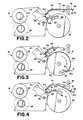
- Figs. 2-4 illustrate the handling of sheet 10 during printing.
- One end of the sheet is fed between a pair of feed rollers 16 of a printer 18. Since both end portions 10b and 10c are of the same length, the sheet may be fed with either end first. Whichever end is fed in first then becomes the leading end, shown generally at 20. The other end, shown generally at 22, is the trailing end. If there was a difference in the amount of unprinted area of the leading and trailing ends of the sheet, then end portions 10b and l0c could be made to have different lengths, and therefore areas, to correspond to this. However, it would also be necessary to feed in the leading edge first each time.
- the input sheet passes through guides 24 and is wrapped around a platen 26 until the leading edge is grasped by a clamp 28.
- Clamp 28 is attached to a drum 30.
- a thermal print head 32 is disposed opposite platen 26.
- a print ribbon 34 extends between takeup rollers 35 and 36, and through the region 38 between the print head and platen where printing takes place.
- sheet 10 is pulled through region 38, with the printed and leading portions of the sheet supported on drum 30, as shown in Fig. 3.
- the sheet is returned along the sheet travel path in the reverse sequence that it was inserted and printed. This is illustrated by Fig. 4.
- FIG. 5 illustrates the beginning of removing of both of these portions from main portion 10a which has an image 40 printed on it.
- Fig. 6 shows main portion 10a remaining after the end portions have been separated. The prior location of the end portions is shown in phantom lines.
- sheet 10 Variations in sheet 10 are possible.
- the main and end portions can be made of different materials. In some applications only one removable end margin may be required. Further, different forms of joints may be used, such as making the end and main portions out of separate pieces of material and linking them together temporarily, such as with adhesive tape.
Landscapes
- Handling Of Sheets (AREA)
- Facsimiles In General (AREA)
- Handling Of Cut Paper (AREA)
Applications Claiming Priority (2)
| Application Number | Priority Date | Filing Date | Title |
|---|---|---|---|
| US23514288A | 1988-08-23 | 1988-08-23 | |
| US235142 | 1988-08-23 |
Publications (2)
| Publication Number | Publication Date |
|---|---|
| EP0355422A2 true EP0355422A2 (fr) | 1990-02-28 |
| EP0355422A3 EP0355422A3 (fr) | 1990-08-22 |
Family
ID=22884272
Family Applications (1)
| Application Number | Title | Priority Date | Filing Date |
|---|---|---|---|
| EP89113475A Withdrawn EP0355422A3 (fr) | 1988-08-23 | 1989-07-21 | Feuille à format réductible |
Country Status (2)
| Country | Link |
|---|---|
| EP (1) | EP0355422A3 (fr) |
| JP (1) | JPH02112974A (fr) |
Cited By (1)
| Publication number | Priority date | Publication date | Assignee | Title |
|---|---|---|---|---|
| US7033095B2 (en) * | 2000-04-20 | 2006-04-25 | Canon Kabushiki Kaisha | Printing paper, print forming process and printing system |
Family Cites Families (2)
| Publication number | Priority date | Publication date | Assignee | Title |
|---|---|---|---|---|
| FR2203711B1 (fr) * | 1972-10-24 | 1979-06-15 | An Controls Inc Di | |
| DE2417154A1 (de) * | 1974-04-09 | 1975-10-23 | Johannes Meyer | Vorrichtung zum trennen von schnelltrenn-formularsaetzen in endlosform |
-
1989
- 1989-07-21 EP EP89113475A patent/EP0355422A3/fr not_active Withdrawn
- 1989-08-21 JP JP21475789A patent/JPH02112974A/ja active Pending
Cited By (1)
| Publication number | Priority date | Publication date | Assignee | Title |
|---|---|---|---|---|
| US7033095B2 (en) * | 2000-04-20 | 2006-04-25 | Canon Kabushiki Kaisha | Printing paper, print forming process and printing system |
Also Published As
| Publication number | Publication date |
|---|---|
| EP0355422A3 (fr) | 1990-08-22 |
| JPH02112974A (ja) | 1990-04-25 |
Similar Documents
| Publication | Publication Date | Title |
|---|---|---|
| DE3935549C2 (de) | Druckvorrichtung | |
| DE4433892B4 (de) | Zeilendrucker mit einem Thermo-Zeilendruckkopf | |
| US5966852A (en) | Directly machine printable index sheet having index tab portions | |
| DE69528556T2 (de) | Verfahren und Vorrichtung zum Drucken auf beiden Seiten eines Blattes | |
| JPH05134824A (ja) | テキストおよびカラー画像プリンタ | |
| GB2218045A (en) | Reprographic processing of sheet material. | |
| US4000916A (en) | Manifold report form and methods for using the same | |
| DE69222225T2 (de) | Druckvorrichtung, die eine plattenförmige Druckschablone herstellt | |
| US4508365A (en) | Continuous form paper with pull tabs for easier separation | |
| US5087238A (en) | Forms Carrier for laser printers | |
| US3305247A (en) | Multiple transfer form and method of making the same | |
| EP0355422A2 (fr) | Feuille à format réductible | |
| US4342472A (en) | Continuous form multiple ply ticket assembly | |
| JPS62141198A (ja) | 記録用紙とその記録用紙の使用方法 | |
| US5634404A (en) | Stencil printing machine | |
| JP2002137538A (ja) | 記録媒体 | |
| US6027600A (en) | Dual simplex printer media and method | |
| JP3013554B2 (ja) | 印字装置 | |
| JPH01118457A (ja) | プリント制御方式 | |
| EP0336610A1 (fr) | Procédé de reprographie et matériau en feuille utilisé pour un tel procédé | |
| JPH06333108A (ja) | 印字発券方法 | |
| JPH01234277A (ja) | 記録装置 | |
| JPS6014622Y2 (ja) | 複写帳票 | |
| JPS63286375A (ja) | 記録装置 | |
| JPH11291687A (ja) | インデックス形成シートおよびそのセットならびにその形成方法 |
Legal Events
| Date | Code | Title | Description |
|---|---|---|---|
| PUAI | Public reference made under article 153(3) epc to a published international application that has entered the european phase |
Free format text: ORIGINAL CODE: 0009012 |
|
| AK | Designated contracting states |
Kind code of ref document: A2 Designated state(s): DE FR GB NL |
|
| PUAL | Search report despatched |
Free format text: ORIGINAL CODE: 0009013 |
|
| AK | Designated contracting states |
Kind code of ref document: A3 Designated state(s): DE FR GB NL |
|
| STAA | Information on the status of an ep patent application or granted ep patent |
Free format text: STATUS: THE APPLICATION IS DEEMED TO BE WITHDRAWN |
|
| 18D | Application deemed to be withdrawn |
Effective date: 19910223 |