EP0355517A2 - Dispositif pour provoquer un écoulement laminaire - Google Patents
Dispositif pour provoquer un écoulement laminaire Download PDFInfo
- Publication number
- EP0355517A2 EP0355517A2 EP89114322A EP89114322A EP0355517A2 EP 0355517 A2 EP0355517 A2 EP 0355517A2 EP 89114322 A EP89114322 A EP 89114322A EP 89114322 A EP89114322 A EP 89114322A EP 0355517 A2 EP0355517 A2 EP 0355517A2
- Authority
- EP
- European Patent Office
- Prior art keywords
- rectangular frame
- laminarizer
- legs
- fabric
- fabric webs
- Prior art date
- Legal status (The legal status is an assumption and is not a legal conclusion. Google has not performed a legal analysis and makes no representation as to the accuracy of the status listed.)
- Granted
Links
Images




Classifications
-
- F—MECHANICAL ENGINEERING; LIGHTING; HEATING; WEAPONS; BLASTING
- F24—HEATING; RANGES; VENTILATING
- F24F—AIR-CONDITIONING; AIR-HUMIDIFICATION; VENTILATION; USE OF AIR CURRENTS FOR SCREENING
- F24F3/00—Air-conditioning systems in which conditioned primary air is supplied from one or more central stations to distributing units in the rooms or spaces where it may receive secondary treatment; Apparatus specially designed for such systems
- F24F3/12—Air-conditioning systems in which conditioned primary air is supplied from one or more central stations to distributing units in the rooms or spaces where it may receive secondary treatment; Apparatus specially designed for such systems characterised by the treatment of the air otherwise than by heating and cooling
- F24F3/16—Air-conditioning systems in which conditioned primary air is supplied from one or more central stations to distributing units in the rooms or spaces where it may receive secondary treatment; Apparatus specially designed for such systems characterised by the treatment of the air otherwise than by heating and cooling by purification, e.g. by filtering; by sterilisation; by ozonisation
- F24F3/167—Clean rooms, i.e. enclosed spaces in which a uniform flow of filtered air is distributed
-
- E—FIXED CONSTRUCTIONS
- E04—BUILDING
- E04B—GENERAL BUILDING CONSTRUCTIONS; WALLS, e.g. PARTITIONS; ROOFS; FLOORS; CEILINGS; INSULATION OR OTHER PROTECTION OF BUILDINGS
- E04B9/00—Ceilings; Construction of ceilings, e.g. false ceilings; Ceiling construction with regard to insulation
- E04B9/02—Ceilings; Construction of ceilings, e.g. false ceilings; Ceiling construction with regard to insulation having means for ventilation or vapour discharge
-
- E—FIXED CONSTRUCTIONS
- E04—BUILDING
- E04B—GENERAL BUILDING CONSTRUCTIONS; WALLS, e.g. PARTITIONS; ROOFS; FLOORS; CEILINGS; INSULATION OR OTHER PROTECTION OF BUILDINGS
- E04B9/00—Ceilings; Construction of ceilings, e.g. false ceilings; Ceiling construction with regard to insulation
- E04B9/04—Ceilings; Construction of ceilings, e.g. false ceilings; Ceiling construction with regard to insulation comprising slabs, panels, sheets or the like
- E04B2009/0492—Ceilings; Construction of ceilings, e.g. false ceilings; Ceiling construction with regard to insulation comprising slabs, panels, sheets or the like with fabrics tensioned on frames
Definitions
- the invention relates to a laminarizer, in particular for clean room ceilings and walls or the like formed from filter modules, which is suspended or held at a distance from a cover carrying the suspended matter filter and consists of a rectangular frame spanned with fabric webs, the legs of the rectangle -Frames consist of triangular hollow profiles or angular profiles in cross-section, on the surfaces facing the space of which the fabric webs have their alignment system.
- the laminarizers formed by the rectangular frames and the adjoining fabric webs are already designed so that the frames have only small cross sections on their outlet side, so that cross currents and turbulence are prevented, which keep contaminants that have entered the clean room in suspension could.
- the fabric webs are glued in their alignment position to the surfaces of the rectangular frames consisting of triangular hollow profiles or angle profiles facing the room.
- the gaps between the mutually facing outer surfaces of adjacent rectangular frames are either completely sealed or else reduced to defined passage cross sections.
- the object of the invention is to provide a laminarator of the type specified at the beginning, in which not only the possible flow disturbances on the outlet side are further minimized with particularly simple means, but at the same time the stability or durability of the connection between the rectangular frame and the fabric webs is improved .
- the basic solution to this problem is that the surfaces of the rectangular frame legs facing the space are only effective as a narrow and / or rounded alignment system for the fabric sheets, while the attachment for the fabric sheets to the normal to the frame level directed outer surfaces and / or on the back surfaces of the rectangular frame legs lying in the frame plane is provided.
- the surfaces of the rectangular frames facing the room can be designed in a manner like a cut, but slightly rounded, so that the formation of flow shadows and the resulting eddy currents is counteracted. Nevertheless, the extent of the fastening surfaces for the fabric sheets can be increased considerably if necessary, so that the holding connection of the fabric sheets to the rectangular frame is significantly improved.
- an adhesive can be provided for fastening the fabric webs - as well as in DE-GM 87 10 781.
- This gluing can not only be provided between the rectangular frame legs and the fabric web, as provided for in claim 3, but also according to claim 4 adhesive strands, e.g. hot melt adhesive, can be inserted in longitudinal recesses, e.g. undercut grooves, of the rectangular frame legs and on the opening side of the longitudinal recess with the fabric web - by melting - to be connected.
- adhesive strands e.g. hot melt adhesive
- the invention advantageously also provides that the fabric webs by means of piping and / or sealing profiles in longitudinal depressions, e.g. undercut grooves, the rectangular frame legs are releasably set.
- the piping profiles can also carry an integrally molded sealing lip which protrudes elastically from the outer surface of the rectangular frame legs.
- Both the flag and / or arcuate edge strips of the fabric webs and the sealing lips of the piping profiles can protrude according to claim 8 into a gap between adjacent rectangular frames and be brought into mutual contact within the same, so that defined leaks are caused by them in the gap.
- the possible flow through the gaps between adjacent rectangular frame legs is advantageously reduced the disturbance of the flow in the wake of the frame.
- a structurally simple configuration of the laminarizers is achieved if, according to claim 10, the rectangular frame legs are connected to one another via corner angles, the legs of which have an angular distance from one another which is between 90 o and 91 o , preferably between 90 o 10 ′ and 90 o 20 ′, lies, the rectangular frame legs are connected to each other to form a rectangular frame under a convex or outwardly curved, elastic pretension.
- the invention provides according to claim 11 that the legs of the corner brackets are held together with a press fit connection with the rectangular frame legs, so that no further connecting means are required.
- corner angles in their outer corner zone have a wall section parallel to the frame plane, which is provided with quarter-circle predetermined breaking points and thereby defines limited breakout areas. Removing these cut-out areas at four adjacent corner angles results in a circular passage, such as is required for energy supply lines or the installation of sprinkler systems. Adjacent to these cut-out areas, namely following the inner corner zone, the corner brackets can also contain circular passages directed transversely to their main plane, through which a fastening element for the laminarizer can be passed.
- the support plate is provided with fastening interventions for each corner of four adjacent rectangular frames, each of which is slidable to a limited extent in the longitudinal and transverse directions on or on the support plate.
- the fastening interventions consist of nuts which can be moved in cages and into which the corner pieces of the rectangular frame screws can be screwed.
- the fastening interventions in the cages can optionally also be designed in the manner of bayonet or ring closures, with which corresponding counterparts can then be brought into engagement, which penetrate the corner pieces of the rectangular frames.
- a laminarizer in which the ceiling fastening consisting of hanging or tensioning rods also carries support plates for bandraids formed from sheet metal profiles, which serve to accommodate cover plates, by means of which the frames of the suspended matter filters for the filter modules can be clamped is finally characterized by the fact that the joints of the band grid are sealed by sheet metal glued on the underside.
- the air conditioning air is supplied through filter modules that are installed under the ceiling and / or in front of the room walls.
- the filter modules are preceded by so-called laminarizers 10 in a plane that is at a distance from them, which are shown in FIGS Partial drawing can be seen.
- a larger number of such laminarizers 10 in a prefabricated standard size are grouped close together and installed in such a way that they are located in front of at least the largest proportion of the area of a ceiling or wall.
- Each laminator 10 consists of a rectangular frame 12 and at least one fine-mesh fabric web 14 braced over this rectangular frame 12, which can be formed, for example, by a metal and / or plastic fabric.
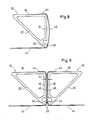
- each rectangular frame 12 is composed of hollow profiles which are approximately triangular in cross section, for example metal or plastic extruded profiles, the two profile walls 16 and 18 being at right angles to one another, while the third profile wall 20 is arranged at an acute angle or obliquely for this purpose.
- the rectangular frame 12 is designed such that the profile walls 18 each form the outer surfaces of its four frame legs 22a, 22b, 22c, 22d, which can be seen in FIG. 10.
- each rectangular frame 12 is determined by the apex zone 24 of the two meeting profile walls 18 and 20 and is therefore very narrow. To avoid a sharp-edged boundary, however, the apex zone 24 is provided with narrow rounded surfaces, as can be clearly seen in FIG. 1.
- each leg 22a to 22d of the rectangular frame 12 which has the rounded portions, forms an alignment system for the fabric webs 14, as can also be clearly seen in FIG. 1.
- the cuts of the fabric webs 14 are dimensioned such that when the same edge strips 26 are tensioned, they can each be guided around the apex zone 24 of the legs 22a to 22d of the rectangular frame 12 and brought into contact with the profile walls 18 forming the outer surfaces thereof.
- the fabric webs 14 are also attached to the profile walls 18 forming the outer surfaces of the rectangular frame, in the exemplary embodiment according to FIG. 1 by attaching adhesives 28, which establish a firm connection of the fabric webs 14 with the rectangular frame 12.
- the bonds 28 are each made on the outer surfaces of the legs 22a to 22d of the rectangular frame 12 so that there are still unsecured areas of the edge strips, which are flag-shaped or protrude from the outer surfaces of the rectangular frame legs 22a to 22d.
- Adjacent laminarizers 10 are installed in such a way that only a small gap distance 32 of a few millimeters remains between the outer surfaces formed by the profile walls 18 of the legs 22a to 22d of the rectangular frame 12, as can also be seen in FIG. 1.
- the flag-shaped sections 30 of the edge strips 26 of the fabric webs 14 come to bear against one another and thereby form a defined leak in the gap distance 32 between the adjacent laminarizers 10.
- the legs 22a to 22d of the rectangular frame 12 do not necessarily have to be produced from hollow profiles which are triangular in cross section. Rather, according to FIG. 2, they can also be formed by simple angular profiles, which only have profile walls 16 and 18 directed at right angles to one another, in which the oblique profile wall 20 is therefore missing.
- the fabric webs 14 are fixed by gluing 28 their edge strips 26 in such a way that the flag-like sections 30 remain free. They also protrude into the gap distance 32 in such a way that they touch one another and there result the desirable, defined leak.
- FIGS. 1 and 2 a different type of fastening for the fabric webs 14 on the legs 22a to 22d of the rectangular frame 12 can be seen than in FIGS. 1 and 2.
- the apex zone 24 in which the outer surface of the Rectangular frame 12 defining profile wall 18 each have a longitudinal recess 34 formed in the form of a circular, undercut groove which extends continuously over the entire length of the profile.
- the edge strips 26 of the fabric sheets 14 can each be anchored with the aid of a so-called keder profile 36, which can be pressed or pressed into the longitudinal recess 34 together with the assigned area of the edge strip 26.
- a strand of hot-melt adhesive 38 is first introduced into the longitudinal recess 34, which is designed as a circular, undercut profile groove, and then the relevant edge strip 26 of the fabric webs 14 comes into contact with it from the outside.
- the hot-melt adhesive strand 38 can now be heated and the fastening connection with the edge strip 26 of the fabric webs 14 can thereby be made.
- the adhesive points can have such a position that flag-like sections 30 of the edge strips 26 remain free and project from the outer surface of the profile frame 12 formed by the profile walls 18.
- FIG. 5 shows in a representation corresponding to FIG. 1 the installation position of two adjacent rectangular frames 12 in the construction shown in FIGS. 3 and 4. It can also be seen there that the gap spacing 32 is present and within it the two flag-like sections 30 of the edge strips 26 touch each other in such a way that they cause a defined leak which causes the laminar Favor flow pattern immediately behind the sounge zones 24, that is to say largely suppress undesired vortex formation.
- FIG. 6 differs from that of FIG. 4 essentially only in that the edge strip 26 of the fabric webs 14 has a width there that almost corresponds to the width of the profile wall 18 of the frame legs 22a to 22d.
- a strip section 40 is present, which is fastened near its longitudinal edge by an additional adhesive 42 so that an arch-like bulge is formed, which protrudes from the profile wall 18 or the outer surface of the rectangular frame 12.
- the width of the edge strip 26 of the fabric webs 14 is dimensioned such that it can be applied to the outside of the legs 22a to 22d of the rectangular frame 12 over the entire width of the profile wall 18 and in addition also a part of the width of the Profile wall 16 can cover. In this case, then only the section 44 of the edge strip 26 is firmly glued to the rear surface formed by the profile wall 16, while the section 46 adjacent to the profile wall 18 remains free, so that it can assume a slight curvature position.
- Fig. 10 of the drawing it is shown - in an exaggerated representation - that the four legs 22a, 22b, 22c and 22d of the rectangular frame 12 are connected to one another by four corner pieces 48 by simply pressing their legs 50 and 52 into the open Ends of the hollow profiles forming the legs 22a to 22d are driven.
- the legs 50 and 52 of each angle piece 48 have an angular distance from each other which is slightly larger than 90 o . It should preferably be between 90 o 10 'and 90 o 20'.
- all the frame legs 22a to 22d are placed on the finished rectangular frame 12 under an elastic prestress, which forces a slight convex or outwardly curved deformation thereof, as indicated by the solid lines in FIG. 10.
- corner pieces 48 for the assembly of the frame 12 can be found in detail in FIGS. 11 and 12.
- each corner piece 48 is preferably to be produced as injection-molded parts made of plastic or else as die-cast parts made of metal and can thereby be given a stable but material-saving configuration.
- each corner piece 48 also has a middle piece 54 which has approximately square contours.
- a passage channel 56 is formed, which connects to the inner corner zone of the middle piece 54 and can be used as a receptacle for a fastener of the rectangular frame.
- the center piece 54 has, in a wall section 58 parallel to the frame plane, predetermined breaking points 60 which run in the shape of a four-part circle and through which correspondingly limited breakout areas 62 are defined.
- breakout areas 62 therefore delimit a circular passage with one another, as is required, for example, for supplying energy or media.
- the connecting lines for sprinkler heads can be easily installed there when the laminarizers 10 are already attached.
- Fig. 13 of the drawing it is indicated that it can be advantageous if the fabric webs 14 in the rectangular frame 12 are only pretensioned to such an extent that they can still sag to a certain extent with respect to the plane of the rectangular frame 12. It has been shown to be particularly advisable if the pretensioning of the fabric webs 14 is selected so that a sagging curve results which has an arc height between 20 and 30 mm. Besides that thereby increasing the durability of the laminarizers 10, the laminar piston flow within a room can also be influenced favorably.
- a special fastening device 64 is used so that the laminarizers 10 can be easily and easily hung up via their corner pieces 48, for example on a ceiling. This consists in the usual way of hanging or tensioning rods 65, with the lower end of which a support plate 66 is connected.
- This support plate 66 has fastening interventions 68 for each corner of four adjacent rectangular frames 12. Each fastening engagement 68 is received in a cage 70 on the support plate 66 so that it can be displaced to a limited extent in the longitudinal and transverse directions.
- the fastening interventions 68 advantageously consist of nuts which have a two-dimensionally displaceable but non-rotatable holder in the cages 70.
- the fastening interventions 68 can also be designed in such a way that they enable interaction with quick-release fasteners, for example in the form of ring or bayonet fasteners.
- fastening interventions 68 are designed as nuts, they can interact with screws which can be passed through the passage channels 56 of the corner pieces 48.
- the laminarizers 10 carried by the fastening devices 64 are generally mounted at a distance from the filter modules of the clean room ceilings and walls.
- the suspended matter filters of these filter modules are supported and fixed with the aid of so-called band grids 72, which are also held by the fastening devices 64.
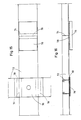
- band rasters 72 are shown schematically simplified.
- the butt joints 74 are each sealed by sheet metal 76 glued on the underside, the adhesive layer 78 which is actually responsible for sealing also being shown.
Landscapes
- Engineering & Computer Science (AREA)
- Architecture (AREA)
- Mechanical Engineering (AREA)
- Chemical & Material Sciences (AREA)
- General Engineering & Computer Science (AREA)
- Physics & Mathematics (AREA)
- Combustion & Propulsion (AREA)
- Electromagnetism (AREA)
- Civil Engineering (AREA)
- Structural Engineering (AREA)
- Filtering Of Dispersed Particles In Gases (AREA)
- Ventilation (AREA)
- Roof Covering Using Slabs Or Stiff Sheets (AREA)
- Paper (AREA)
- Steroid Compounds (AREA)
Priority Applications (1)
| Application Number | Priority Date | Filing Date | Title |
|---|---|---|---|
| AT89114322T ATE75022T1 (de) | 1988-08-17 | 1989-08-03 | Laminarisator. |
Applications Claiming Priority (2)
| Application Number | Priority Date | Filing Date | Title |
|---|---|---|---|
| DE3827918 | 1988-08-17 | ||
| DE3827918A DE3827918A1 (de) | 1988-08-17 | 1988-08-17 | Laminarisator |
Publications (3)
| Publication Number | Publication Date |
|---|---|
| EP0355517A2 true EP0355517A2 (fr) | 1990-02-28 |
| EP0355517A3 EP0355517A3 (en) | 1990-11-14 |
| EP0355517B1 EP0355517B1 (fr) | 1992-04-15 |
Family
ID=6361039
Family Applications (1)
| Application Number | Title | Priority Date | Filing Date |
|---|---|---|---|
| EP89114322A Expired - Lifetime EP0355517B1 (fr) | 1988-08-17 | 1989-08-03 | Dispositif pour provoquer un écoulement laminaire |
Country Status (5)
| Country | Link |
|---|---|
| US (1) | US4898087A (fr) |
| EP (1) | EP0355517B1 (fr) |
| AT (1) | ATE75022T1 (fr) |
| DE (2) | DE3827918A1 (fr) |
| ES (1) | ES2031322T3 (fr) |
Cited By (2)
| Publication number | Priority date | Publication date | Assignee | Title |
|---|---|---|---|---|
| EP2048299A3 (fr) * | 2004-01-28 | 2010-06-09 | Soft Cells A/S | Panneau de recouvrement en particulier pour faux plafond |
| EP2047776B1 (fr) * | 2007-10-09 | 2013-10-09 | Normalu | Dispositif et procédé le mettant en oeuvre pour la tension d'une toile sur un élément en relief |
Families Citing this family (14)
| Publication number | Priority date | Publication date | Assignee | Title |
|---|---|---|---|---|
| DE4312959B4 (de) * | 1993-04-21 | 2005-12-29 | Heinrich Nickel Gmbh | Reinraumdecke |
| US5470363A (en) * | 1995-01-13 | 1995-11-28 | Envirco Corporation | Air blower and filter assemblies |
| US5782689A (en) * | 1996-01-11 | 1998-07-21 | Tomkins Industries Inc. | Fabric faced air distribution device |
| US6059655A (en) * | 1996-01-24 | 2000-05-09 | Chemfab Corporation | Fabric air diffuser, method for diffusing air, and method for attenuating noise associated with flowing air |
| US6425821B1 (en) | 1996-01-24 | 2002-07-30 | Chemfab Corporation | Pore-containing web for diffusing fluids |
| US5725427A (en) * | 1996-01-24 | 1998-03-10 | Chemfab Corporation | Fabric air diffuser, method for diffusing air, and method for attenuating noise associated with flowing air |
| US5885154A (en) * | 1997-06-17 | 1999-03-23 | Napadow; Michael F. | Air supply means for a controlled environment room |
| SE512715C2 (sv) * | 1998-07-27 | 2000-05-02 | Flaekt Ab | Laminärflödesram |
| DE19943479A1 (de) * | 1999-09-10 | 2001-04-12 | Manfred Kluth | Abgehängtes Deckensystem |
| DE19943478C2 (de) * | 1999-09-10 | 2002-11-28 | Manfred Kluth | Beleuchtungskörper mit teilweise lichtdurchlässigen Folien |
| US6413159B1 (en) | 2000-06-28 | 2002-07-02 | The Boeing Company | Airplane cabin overhead air outlets |
| DE102014004921B3 (de) * | 2014-04-07 | 2015-04-16 | Innovations-Transfer Uphoff Gmbh & Co. Kg | Reinraumbeleuchtungsvorrichtung |
| DE102014004922B3 (de) | 2014-04-07 | 2015-03-12 | Innovations-Transfer Uphoff Gmbh &.Co.Kg | Laminarisatorpassagevorrichtung |
| JP2022163909A (ja) * | 2021-04-15 | 2022-10-27 | 株式会社エアレックス | 整流部材及びこれを用いた室内整流システム |
Family Cites Families (10)
| Publication number | Priority date | Publication date | Assignee | Title |
|---|---|---|---|---|
| US2221001A (en) * | 1936-10-27 | 1940-11-12 | Johns Manville | Ventilating ceiling |
| US2276788A (en) * | 1938-06-27 | 1942-03-17 | Burgess Battery Co | Building construction |
| CH578660A5 (fr) * | 1973-11-15 | 1976-08-13 | Henggeler Aldo | |
| US4175936A (en) * | 1977-09-06 | 1979-11-27 | Weber Technical Products Division of Craig Systems Corp. | Diffuser with replaceable filter |
| US4371386A (en) * | 1981-05-18 | 1983-02-01 | Veco International, Inc. | Filter housing |
| DE3447901C2 (de) * | 1984-12-28 | 1994-07-07 | Flaekt Ab | Von der Decke eines Raumes abhängbare modulare Rahmenanordnung zur Aufnahme von Filtern mit Fluiddichtung für Reinraumdecken |
| DE3605539A1 (de) * | 1986-02-18 | 1987-08-20 | Herbst Donald | Vorrichtung zum zufuehren eines luftstroms in einen raum |
| DE8710781U1 (de) * | 1987-05-16 | 1987-10-01 | Heinrich Nickel Gmbh, 5240 Betzdorf | Filtermodul für Reinraumdecken und -wände o.dgl. |
| DE8707512U1 (de) * | 1987-05-26 | 1988-06-23 | Haensel, Dietrich, 40789 Monheim | Trägerrahmen für Filtermatten, wobei die Trägerrahmen aus Kunststoffspritzguß bestehen und an der Filtermatte verklebt oder thermofixiert sind |
| JPH03176944A (ja) * | 1989-12-06 | 1991-07-31 | Hitachi Ltd | 搬送装置 |
-
1988
- 1988-08-17 DE DE3827918A patent/DE3827918A1/de not_active Withdrawn
-
1989
- 1989-03-17 US US07/325,363 patent/US4898087A/en not_active Expired - Lifetime
- 1989-08-03 DE DE8989114322T patent/DE58901152D1/de not_active Expired - Lifetime
- 1989-08-03 EP EP89114322A patent/EP0355517B1/fr not_active Expired - Lifetime
- 1989-08-03 AT AT89114322T patent/ATE75022T1/de not_active IP Right Cessation
- 1989-08-03 ES ES198989114322T patent/ES2031322T3/es not_active Expired - Lifetime
Cited By (2)
| Publication number | Priority date | Publication date | Assignee | Title |
|---|---|---|---|---|
| EP2048299A3 (fr) * | 2004-01-28 | 2010-06-09 | Soft Cells A/S | Panneau de recouvrement en particulier pour faux plafond |
| EP2047776B1 (fr) * | 2007-10-09 | 2013-10-09 | Normalu | Dispositif et procédé le mettant en oeuvre pour la tension d'une toile sur un élément en relief |
Also Published As
| Publication number | Publication date |
|---|---|
| EP0355517A3 (en) | 1990-11-14 |
| ATE75022T1 (de) | 1992-05-15 |
| US4898087A (en) | 1990-02-06 |
| EP0355517B1 (fr) | 1992-04-15 |
| DE58901152D1 (de) | 1992-05-21 |
| DE3827918A1 (de) | 1990-02-22 |
| ES2031322T3 (es) | 1992-12-01 |
Similar Documents
| Publication | Publication Date | Title |
|---|---|---|
| EP0355517B1 (fr) | Dispositif pour provoquer un écoulement laminaire | |
| DE1279433B (de) | Plattenfoermiger Luftfiltereinsatz und Verfahren zu seiner Herstellung | |
| DE69318421T2 (de) | Fenstersprosse | |
| DE2049775B2 (de) | Trogförmiger Vorhangschienenkasten | |
| DE60014197T2 (de) | Deckenvorrichtung | |
| DE69736477T2 (de) | Luftfiltersystem für reinraum mit selbsttragenden filtereinheiten | |
| DE29601640U1 (de) | Vorrichtung zur vorläufigen Halterung von Einsatzteilen in Riegel- und Pfostenfassaden. | |
| DE10221375A1 (de) | Dichtungsanordnung für eine Wärmerückgewinnungszelle | |
| CH639165A5 (en) | Panel element with a sound-insulating mat, in particular for soundproofing walls, soundproofing floors and soundproofing booths | |
| DE3402967A1 (de) | Akustische wand | |
| DE19603433C2 (de) | Vorrichtung zur vorläufigen Halterung von Einsatzteilen in Riegel- und Pfostenfassaden | |
| DE3241424C2 (de) | Verbindungseinrichtung | |
| DE3204199A1 (de) | Montageblock | |
| EP0291783A2 (fr) | Module de filtre pour plafonds, murs de chambres antiseptiques, etc. | |
| DE865651C (de) | Rahmen, insbesondere fuer Schaufenster | |
| AT383857B (de) | Fensterzarge | |
| DE2756207A1 (de) | Vorrichtung zur befestigung von fensterscheiben, insbesondere fahrzeugscheiben | |
| EP0253312A2 (fr) | Construction de cabine | |
| DE2721541A1 (de) | Verbindungsanordnung fuer rasterdecken | |
| DE29923857U1 (de) | Filterplatte für Filterpressen | |
| DE3516013A1 (de) | Bauelementsatz fuer raumdecken | |
| DE10131837B4 (de) | Lichtdecke oder Lichtwand | |
| DE2828338C2 (de) | Rechteckiger Deckenauslaß | |
| EP0037498B1 (fr) | Dispositif pour filtre à poche | |
| DE2628923C3 (de) | Vorrichtung zum Be- und Entlüften eines mit großformatigen Dacheindeckungsplatten eingedeckten Kaltdachs |
Legal Events
| Date | Code | Title | Description |
|---|---|---|---|
| PUAI | Public reference made under article 153(3) epc to a published international application that has entered the european phase |
Free format text: ORIGINAL CODE: 0009012 |
|
| 17P | Request for examination filed |
Effective date: 19890816 |
|
| AK | Designated contracting states |
Kind code of ref document: A2 Designated state(s): AT DE ES FR GB NL |
|
| PUAL | Search report despatched |
Free format text: ORIGINAL CODE: 0009013 |
|
| RHK1 | Main classification (correction) |
Ipc: F24F 3/16 |
|
| AK | Designated contracting states |
Kind code of ref document: A3 Designated state(s): AT DE ES FR GB NL |
|
| 17Q | First examination report despatched |
Effective date: 19910201 |
|
| GRAA | (expected) grant |
Free format text: ORIGINAL CODE: 0009210 |
|
| AK | Designated contracting states |
Kind code of ref document: B1 Designated state(s): AT DE ES FR GB NL |
|
| REF | Corresponds to: |
Ref document number: 75022 Country of ref document: AT Date of ref document: 19920515 Kind code of ref document: T |
|
| REF | Corresponds to: |
Ref document number: 58901152 Country of ref document: DE Date of ref document: 19920521 |
|
| GBT | Gb: translation of ep patent filed (gb section 77(6)(a)/1977) | ||
| ET | Fr: translation filed | ||
| REG | Reference to a national code |
Ref country code: ES Ref legal event code: FG2A Ref document number: 2031322 Country of ref document: ES Kind code of ref document: T3 |
|
| PLBE | No opposition filed within time limit |
Free format text: ORIGINAL CODE: 0009261 |
|
| STAA | Information on the status of an ep patent application or granted ep patent |
Free format text: STATUS: NO OPPOSITION FILED WITHIN TIME LIMIT |
|
| 26N | No opposition filed | ||
| PGFP | Annual fee paid to national office [announced via postgrant information from national office to epo] |
Ref country code: FR Payment date: 19930727 Year of fee payment: 5 |
|
| PGFP | Annual fee paid to national office [announced via postgrant information from national office to epo] |
Ref country code: GB Payment date: 19930730 Year of fee payment: 5 |
|
| PGFP | Annual fee paid to national office [announced via postgrant information from national office to epo] |
Ref country code: ES Payment date: 19930802 Year of fee payment: 5 |
|
| PG25 | Lapsed in a contracting state [announced via postgrant information from national office to epo] |
Ref country code: GB Effective date: 19940803 |
|
| PG25 | Lapsed in a contracting state [announced via postgrant information from national office to epo] |
Ref country code: ES Free format text: LAPSE BECAUSE OF THE APPLICANT RENOUNCES Effective date: 19940804 |
|
| GBPC | Gb: european patent ceased through non-payment of renewal fee |
Effective date: 19940803 |
|
| PG25 | Lapsed in a contracting state [announced via postgrant information from national office to epo] |
Ref country code: FR Effective date: 19950428 |
|
| REG | Reference to a national code |
Ref country code: FR Ref legal event code: ST |
|
| REG | Reference to a national code |
Ref country code: ES Ref legal event code: FD2A Effective date: 19991007 |
|
| PGFP | Annual fee paid to national office [announced via postgrant information from national office to epo] |
Ref country code: AT Payment date: 20050628 Year of fee payment: 17 |
|
| PGFP | Annual fee paid to national office [announced via postgrant information from national office to epo] |
Ref country code: NL Payment date: 20050812 Year of fee payment: 17 |
|
| PG25 | Lapsed in a contracting state [announced via postgrant information from national office to epo] |
Ref country code: AT Free format text: LAPSE BECAUSE OF NON-PAYMENT OF DUE FEES Effective date: 20060803 |
|
| PG25 | Lapsed in a contracting state [announced via postgrant information from national office to epo] |
Ref country code: NL Free format text: LAPSE BECAUSE OF NON-PAYMENT OF DUE FEES Effective date: 20070301 |
|
| NLV4 | Nl: lapsed or anulled due to non-payment of the annual fee |
Effective date: 20070301 |
|
| PGFP | Annual fee paid to national office [announced via postgrant information from national office to epo] |
Ref country code: DE Payment date: 20080915 Year of fee payment: 20 |