EP0355576A1 - Système de commande de secousse pour un système de propulsion - Google Patents
Système de commande de secousse pour un système de propulsion Download PDFInfo
- Publication number
- EP0355576A1 EP0355576A1 EP89114681A EP89114681A EP0355576A1 EP 0355576 A1 EP0355576 A1 EP 0355576A1 EP 89114681 A EP89114681 A EP 89114681A EP 89114681 A EP89114681 A EP 89114681A EP 0355576 A1 EP0355576 A1 EP 0355576A1
- Authority
- EP
- European Patent Office
- Prior art keywords
- engine
- transmission
- gear ratio
- revolution speed
- torque
- Prior art date
- Legal status (The legal status is an assumption and is not a legal conclusion. Google has not performed a legal analysis and makes no representation as to the accuracy of the status listed.)
- Granted
Links
Images






Classifications
-
- B—PERFORMING OPERATIONS; TRANSPORTING
- B60—VEHICLES IN GENERAL
- B60W—CONJOINT CONTROL OF VEHICLE SUB-UNITS OF DIFFERENT TYPE OR DIFFERENT FUNCTION; CONTROL SYSTEMS SPECIALLY ADAPTED FOR HYBRID VEHICLES; ROAD VEHICLE DRIVE CONTROL SYSTEMS FOR PURPOSES NOT RELATED TO THE CONTROL OF A PARTICULAR SUB-UNIT
- B60W30/00—Purposes of road vehicle drive control systems not related to the control of a particular sub-unit, e.g. of systems using conjoint control of vehicle sub-units
- B60W30/18—Propelling the vehicle
-
- B—PERFORMING OPERATIONS; TRANSPORTING
- B60—VEHICLES IN GENERAL
- B60W—CONJOINT CONTROL OF VEHICLE SUB-UNITS OF DIFFERENT TYPE OR DIFFERENT FUNCTION; CONTROL SYSTEMS SPECIALLY ADAPTED FOR HYBRID VEHICLES; ROAD VEHICLE DRIVE CONTROL SYSTEMS FOR PURPOSES NOT RELATED TO THE CONTROL OF A PARTICULAR SUB-UNIT
- B60W10/00—Conjoint control of vehicle sub-units of different type or different function
- B60W10/04—Conjoint control of vehicle sub-units of different type or different function including control of propulsion units
-
- B—PERFORMING OPERATIONS; TRANSPORTING
- B60—VEHICLES IN GENERAL
- B60W—CONJOINT CONTROL OF VEHICLE SUB-UNITS OF DIFFERENT TYPE OR DIFFERENT FUNCTION; CONTROL SYSTEMS SPECIALLY ADAPTED FOR HYBRID VEHICLES; ROAD VEHICLE DRIVE CONTROL SYSTEMS FOR PURPOSES NOT RELATED TO THE CONTROL OF A PARTICULAR SUB-UNIT
- B60W10/00—Conjoint control of vehicle sub-units of different type or different function
- B60W10/10—Conjoint control of vehicle sub-units of different type or different function including control of change-speed gearings
- B60W10/11—Stepped gearings
-
- B—PERFORMING OPERATIONS; TRANSPORTING
- B60—VEHICLES IN GENERAL
- B60W—CONJOINT CONTROL OF VEHICLE SUB-UNITS OF DIFFERENT TYPE OR DIFFERENT FUNCTION; CONTROL SYSTEMS SPECIALLY ADAPTED FOR HYBRID VEHICLES; ROAD VEHICLE DRIVE CONTROL SYSTEMS FOR PURPOSES NOT RELATED TO THE CONTROL OF A PARTICULAR SUB-UNIT
- B60W30/00—Purposes of road vehicle drive control systems not related to the control of a particular sub-unit, e.g. of systems using conjoint control of vehicle sub-units
- B60W30/18—Propelling the vehicle
- B60W30/1819—Propulsion control with control means using analogue circuits, relays or mechanical links
-
- F—MECHANICAL ENGINEERING; LIGHTING; HEATING; WEAPONS; BLASTING
- F16—ENGINEERING ELEMENTS AND UNITS; GENERAL MEASURES FOR PRODUCING AND MAINTAINING EFFECTIVE FUNCTIONING OF MACHINES OR INSTALLATIONS; THERMAL INSULATION IN GENERAL
- F16H—GEARING
- F16H61/00—Control functions within control units of change-speed- or reversing-gearings for conveying rotary motion ; Control of exclusively fluid gearing, friction gearing, gearings with endless flexible members or other particular types of gearing
- F16H61/04—Smoothing ratio shift
- F16H61/0437—Smoothing ratio shift by using electrical signals
-
- F—MECHANICAL ENGINEERING; LIGHTING; HEATING; WEAPONS; BLASTING
- F16—ENGINEERING ELEMENTS AND UNITS; GENERAL MEASURES FOR PRODUCING AND MAINTAINING EFFECTIVE FUNCTIONING OF MACHINES OR INSTALLATIONS; THERMAL INSULATION IN GENERAL
- F16H—GEARING
- F16H59/00—Control inputs to control units of change-speed- or reversing-gearings for conveying rotary motion
- F16H59/68—Inputs being a function of gearing status
- F16H2059/6807—Status of gear-change operation, e.g. clutch fully engaged
-
- F—MECHANICAL ENGINEERING; LIGHTING; HEATING; WEAPONS; BLASTING
- F16—ENGINEERING ELEMENTS AND UNITS; GENERAL MEASURES FOR PRODUCING AND MAINTAINING EFFECTIVE FUNCTIONING OF MACHINES OR INSTALLATIONS; THERMAL INSULATION IN GENERAL
- F16H—GEARING
- F16H63/00—Control outputs from the control unit to change-speed- or reversing-gearings for conveying rotary motion or to other devices than the final output mechanism
- F16H63/40—Control outputs from the control unit to change-speed- or reversing-gearings for conveying rotary motion or to other devices than the final output mechanism comprising signals other than signals for actuating the final output mechanisms
- F16H63/50—Signals to an engine or motor
- F16H63/502—Signals to an engine or motor for smoothing gear shifts
Definitions
- the present invention relates to a jolt control system for a drive system including a prime mover and an automatic transmission.
- U.S. Patent No. 4,266,447 teaches detecting the start and termination of a shift operation by monitoring the revolution speed of output shaft of the prime mover.
- This known method requires data map which a synchronizing speed value is taken from.
- This data map has to be designed to take due consideration of the situation where the vehicle speed changes during the shift operation or the situation where the wheel acceleration varies during the shift operation.
- An object of the present invention is to provide a jolt control system which is improved such that the period of a shift operation is detected accurately under any circumsnatnces.
- an apparent gear ratio namely a ratio of the transmission input revolution speed to the transmission output revolution speed
- the engine output torque is alterted when the apparent gear ratio falls between two gear ratios established before and after a shift operation, thus providing a shock-less shift operation.
- a jolt control method for a drive system including an engine, a torque converter, and an automatic transmission to which the engine output torque is transmitted through the torque converter, the automatic transmission being subjected to a shift operation from one speed with a first gear ratio to another speed with a second gear ratio, the automatic transmission having a transmission output shaft and a transmission input shaft which is drivingly connected via the torque converter to the engine, the jolt control method comprising the steps of: detecting a revolution speed of the transmission input shaft and generating a transmission input revolution speed indicative signal; detecting a revolution speed of the transmission output shaft and generating a transmission output revolution speed indicative signal; determining an apparent gear ratio based on said transmission input and output revolution speed indicative signals and generating a shift operation indicative signal when said apparent gear ratio falls between the first and second gear ratios; and causing the engine to temporarily alter output torque thereof in response to said shift operation indicative signal.
- Fig. 1 shows one embodiment of a jolt control system according to the invention, in which 1 denotes an engine serving as a prime mover and 2 denotes an automatic transmission.
- the power of the engine 1 is delivered through a torque converter 3 to the automatic transmission 2, which allows delivery of the power to a transmission output shaft 4 in a manner to drive the driving wheels of the vehicle in accordance with a gear ratio provided by the gear position established in the automatic transmission.
- the engine 1 is an eight-cylidner engine having eight fuel injection valves 5 for eight cylinders, respectively. These fuel injection valves 5 are opened or closed by an engine control computer 6.
- the computer 6 calculates and determines the amount of fuel to be injected in response to an engine speed indicative signal sent from an engine speed sensor 7 which detects the engine crankshaft revolution speed N E , an engine coolant temperature indicative signal from an engine coolant temperature sensor 8 which detects a temperature C of an engine coolant, and a throttle opening degree indiative signal from a throttle sensor 9 which detects a throttle opening degree TH representative of an engine load.
- the computer 6 operates to individually open each fuel injection valve 5 for a duration of time which is variable with variations in to the engine speed N E for allowing fuel to be injected to the corresponding cylinders of the engine 1.
- the automatic transmission 2 has a control valve assembly 10.
- the control valve assembly 10 has a first shift solenoid 11, a second shift solenoid 12, and line pressure solenoid 13.
- the shift solenoids 11 and 12 are rendered ON (energized) and/or OFF (deenergized) or vice versa in a manner as tabuleted in Table 1 as follows: Table 1 First Shift Solenoid 11 Second Shift Solenoid 12 First Speed ON ON Second Speed OFF ON Third Speed OFF OFF Fourth Speed ON OFF
- the servo activating hydraulic pressure for respective friction elements is a line pressure which is generated as a result of pressure regulation under the control of the line pressure solenoid 13 that is duty controlled.
- the capacity of a friction element to be hydraulically activated is controlled by temporarily modulating the line pressure.
- the on-off control of the solenoids 11, 12 and the duty control of the line pressure solenoid 13 are executed by an automatic transmission control computer 15.
- the computer 15 performs various functions which may be illustrated by circuits or stages 16, 17, 18, 19 and 20 for deciding gear position, for deciding number of disabled cylinders by fuel-cut, for detecting gear shifting, for outputting demand for fuel-cut, and for deciding line pressure.
- the automatic transmission mentioned above is of the RE4R01A type described in "NISSAN FULL-RANGE AUTOMATIC TRANSMISSION RE4R01A TYPE, SERVICE MANUAL, (A261C07)" issued on March, 1987 by NISSAN MOTOR COMPANY LIMITED.
- the automatic transmission of the above mentioned type is also disclosed inUnited States Patent No. 4,680,992 (Hayasaki et al.) which is hereby incorporated in its entirety by reference.
- a desired shift in gear position is determined by looking up a predetermined shift pattern table using the throttle opening degree indicative signal TH (engine load) and the transmission output shaft revolution speed indicative signal N O (vehicle speed) and controls the ON/OFF state of the shift solenoids 11, 12 to establish the gear position desired.
- a step 30 it is determined whether the fuel-cut operation is possible or not by checking whether or not the engine speed N E is greater than or equal to a predetermined value, a coolant temperature C is higher than or equal to a predetermined value, and there is issued the fuel-cut enable signal from the engine control computer 6. If it is determined that the fuel-cut operation is not possible, the number of cylinders to be disabled (viz., disabled cylinder) to zero at a step 31.
- the program proceeds to steps 32 to 34 to determine which of different types of shift the desired shift determined at the stage 16 belongs to. If the desired shift determined at the stage 16 is a downshift or no shift is required, the program proceeds through all of the steps 32, 33 and 34 to the step 31 where the number of diabled cylinders is set to 0 (zero) since this is where the engine output reduction control is not required.
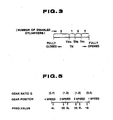
- the desired shift determined is found to be a 1-2 upshift at the step 32, it is determined at steps 35 to 37 which of four regions the throttle opening degree TH falls in. As shown in Fig. 3, these four regions correspond to different numbers of disabled cylinders, respectively, and thus used for evaluating the number of disabled cylinders for effective reduction of the shift shock during the 1-2 upshift operation.
- TH ⁇ TH1 the number of disabled cylinders is set to 4 at a step 38 to allow the fuel-cut to four cylinders.
- the number of disabled cylinders is set to 2 at a step 39 to allow fuel-cut to two cylinders.
- the number of disabled cylinders is set to 1 at a step 40 to allow the fuel-cut to one cylinder.
- the TH ⁇ TH3, the number of disabled cylinders is set to 0 (zero) at the step 31 to prohibit fuel-cut operation.
- Fig. 4 the function to detect gear shifting performed at the stage 18 is explained. Supplied to this stage 18 are the transmission input shaft revolution speed N T , the transmission output shaft revolution speed N O and the desired shift determined at the stage 16.
- N T the transmission input shaft revolution speed
- N O the transmission output shaft revolution speed
- a step 50 an apparent gear ratio N T /N O is calculated.
- the type which the desired shift determined at the stage 16 belongs to is evaluated at steps 51 to 53. If the desired shift determined at the stage 16 is found to be a downshift or no shift is required, it is unnecessary to reduce the engine output during the shift operation. Thus, a flag F1 indicating that the shift operation is under progress is reset to 0 (zero).
- the gear ratio G is checked at the corresponding one of steps 55, 56, and 57 to determine whether or not the upshift operation progresses.
- the flag F1 is set to 1 at the corresponding step 58 or 59 or 60. If it is found that the upshift operation is not yet initiated or completed, the flag F1 is reset to zero at the corresponding step 54 or 61.
- Fig. 6 the function to output demand for fuel-cut operation performed at the circuit or stage 19 is explained.
- the demand for fuel-cut is fed to the engine control computer 6 to cut fuel supply to some of the cylinders of the engine 1 to urge the engine 1 to reduce output torque thereof.
- Supplied to the stage 19 are the signal indicative of the state of the flag F1 determined at the stage 18 (see flowchart shown in Fig. 4) and the signal indicative of the number of disabled cylinders set at the stage 17 (see flowchart shown in Fig. 2).
- F1 1, that is, whether the upshift is under progress or not.
- step 72 a demand to disable zero cylinder is outputted, that is, the fuel supply to all of the cylinders is maintained (no fuel-cut). If the flag F1 is found to be set at the step 70, and if the number of disabled cylinders is zero at a step 71, the program proceeds to the step 72 where the demand to disable zero cylinder is outputted to the engine control computer 6. If the number of disabled cylinders is found to be 1 at a step 73, there is outputted demand to disable one cylinder at a step 74.
- step 75 there is outputted a demand to disable two cylinders at a step 76. If at the step 75 it is determined that the number of disabled cylinders is not 2, there is outputted a demand to disable four cylinders at a step 77. In response to the demand outputted, one or some of the fuel injection valves 5 are closed to disable the number of cylinders demanded under the control of the engine control computer 6 during the upshift operation.
- the amount of reduction of output torque of the engine is best matched to the amount of torque reduction for reducing the shift shock which varies with varying operation state of the drive system since the number of cylinders which are to be disabled by fuel-cut is altered in response to the operation state of the drive system (such as, type of shift operation which the automatic transmission is subjected to, and throttle opening degree TH), thus contributing to reduction of shift shock during the shift operation.
- whether the upshift operation is in progress or not is accurately determined by the change of the gear ratio G. This assures the synchronization of the occurrence of the engine output torque change with the occurrence of the shift operation, thus eliminating the possibility of inducing a new shock or degrading the driving performance.
- the line pressure deciding stage 20 shown in Fig. 1 receives the throttle opening degree TH indicative signal from the sensor 9 to determine the duty which the line pressure solenoid 13 is operated on such that the magnitude of the line pressure is adjusted in response to the throttle opening degree TH.
- the automatic transmission control computer 15 is equivalent to the combination of a gear position deciding circuit 16, a shifting detecting circuit 23, a torque-up demand outputting circuit 24, and a line pressure deciding circuit 25.
- the gear position deciding circuit 16 is the same as the circuit shown with the same numeral in Fig. 1.
- the shifting detecting circuit 23 executes the function as illustrated by program shown Fig. 8 on the basis of the revolution speeds N T and N O fed from the sensor 22, 21 as well as the type of the gear shift fed from the gear position deciding circuit 16 so as to detect whether the downshift is being under way or not.
- the apparent gear ratio G N T /N O is calculated, and in the next step 81, it is checked to see whether a downshift or the other, such as an upshift or non-shifting, is performed.
- the torque-up operation for reducing the shift shock is not necessary in the upshift or non-shifting so that the flag F2 is reset to 0 in the step 82 to indicate this.
- the downshift is performed, it is checked in the step 83, 84 to see whether the downshift is a downshift to the first speed, downshift to the second speed or downshift to the third speed.
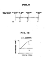
- the gear ratio M for identifying the termination of each downshift is set to ⁇ 1, ⁇ 2 or ⁇ 3 as shown in Fig.
- the flag F3 is set to 1 to indicate that the torque-down operation is not necessary.
- the torque-up demand outputting circuit 24 in Fig. 7 executes the control program shown in Fig. 10 and Fig. 11 on the basis of the information of the flag F2 and the information on the types of the shift fed from the stage 16 to allow the engine control computer 6 to increase the output torque thereof (torque-up) for reducing the downshift shock and to decrease the output (torque-down).
- the step 91 it is checked in the step 91 to see whether the downshift is preformed or not, the torque-up demand signal is not fed to the engine control computer 6.
- the step 93 it is checked in the step 93 to see whether this shift is performed or not on the basis of the state of the flag F2.
- a timer T1 is set in the step 113 to perform the torque-down control until the timer T1 reaches 0.
- the torque-down control is stopped.
- the count of the timer T1 is decreased by one. This torque-down control is performed to achieve a shock-less and smooth termination of the shift operation by preventing the excessive engine speed increase due to the torque-up control.
- the line pressure deciding stage 25 shown in Fig. 7 executes the control program shown in Fig. 12 on the basis of the information on the opening degree of the throttle (TH) fed from the sensor 9 and the information on the type of the shift fed from the stage 16 to control the magnitude of the line pressure to the value that is neither excessive nor insufficient. Thus, it is checked in the step 95 to see whether the downshift is performed or not. If it is not the downshift, the line pressure characteristics for the corresponding non-shifting or upshift are retrieved in the step 96 ordinarily so as to control the line pressure by feeding the corresponding duty to the line pressure solenoid 13.
- the downshift it is checked in the step 97 to see whether or not the 2-1 downshift is performed.
- the same processing as that enclosed in the block 101 is performed in the step 102 for each type of the shift operation to perform the specified line pressure control.
Landscapes
- Engineering & Computer Science (AREA)
- Mechanical Engineering (AREA)
- Chemical & Material Sciences (AREA)
- Combustion & Propulsion (AREA)
- Transportation (AREA)
- Automation & Control Theory (AREA)
- General Engineering & Computer Science (AREA)
- Control Of Transmission Device (AREA)
- Control Of Driving Devices And Active Controlling Of Vehicle (AREA)
- Control Of Vehicle Engines Or Engines For Specific Uses (AREA)
- Electrical Control Of Air Or Fuel Supplied To Internal-Combustion Engine (AREA)
Applications Claiming Priority (2)
| Application Number | Priority Date | Filing Date | Title |
|---|---|---|---|
| JP63196078A JPH0245628A (ja) | 1988-08-08 | 1988-08-08 | パワートレーンの変速ショック軽減用総合制御装置 |
| JP196078/88 | 1988-08-08 |
Publications (2)
| Publication Number | Publication Date |
|---|---|
| EP0355576A1 true EP0355576A1 (fr) | 1990-02-28 |
| EP0355576B1 EP0355576B1 (fr) | 1993-12-01 |
Family
ID=16351835
Family Applications (1)
| Application Number | Title | Priority Date | Filing Date |
|---|---|---|---|
| EP89114681A Expired - Lifetime EP0355576B1 (fr) | 1988-08-08 | 1989-08-08 | Système de commande de secousse pour un système de propulsion |
Country Status (4)
| Country | Link |
|---|---|
| US (1) | US5119696A (fr) |
| EP (1) | EP0355576B1 (fr) |
| JP (1) | JPH0245628A (fr) |
| DE (1) | DE68911059T2 (fr) |
Cited By (2)
| Publication number | Priority date | Publication date | Assignee | Title |
|---|---|---|---|---|
| GB2310011A (en) * | 1995-11-29 | 1997-08-13 | Siemens Ag | Smoothing shift in an automatic gearbox using engine torque reduction |
| EP1138986A1 (fr) * | 2000-03-30 | 2001-10-04 | Hitachi Ltd. | Procédé et dispositif de commande d'une transmission automatique |
Families Citing this family (14)
| Publication number | Priority date | Publication date | Assignee | Title |
|---|---|---|---|---|
| DE4327906B4 (de) * | 1993-08-19 | 2006-05-24 | Bayerische Motoren Werke Ag | Vorrichtung zur Reduzierung des Brennkraftmaschinenmoments bei Schaltvorgängen eines Getriebes |
| IT1266914B1 (it) * | 1994-08-05 | 1997-01-21 | Magneti Marelli Spa | Sistema di controllo di un cambio servoassistito. |
| DE4441896B4 (de) * | 1994-11-24 | 2009-10-08 | Continental Automotive Gmbh | Steuerung für ein Kraftfahrzeug |
| JP3630198B2 (ja) * | 1996-04-30 | 2005-03-16 | 本田技研工業株式会社 | 車両用内燃エンジン制御装置 |
| JP3594733B2 (ja) * | 1996-04-30 | 2004-12-02 | 本田技研工業株式会社 | 車両用内燃エンジン制御装置 |
| US5879266A (en) * | 1997-01-17 | 1999-03-09 | Honda Giken Kogyo Kabushiki Kaisha | Control system for internal combustion engines |
| DE19747270A1 (de) * | 1997-10-25 | 1999-04-29 | Bayerische Motoren Werke Ag | Kraftfahrzeug mit einem Automatikgetriebe |
| JP3230515B2 (ja) * | 1998-04-14 | 2001-11-19 | 日産自動車株式会社 | 手動変速可能な自動変速機の変速制御装置 |
| US7063234B2 (en) * | 2000-12-29 | 2006-06-20 | Csp Technologies, Inc. | Meter strip dispenser assembly |
| JPWO2003029697A1 (ja) * | 2001-09-28 | 2005-01-20 | ジヤトコ株式会社 | 自動変速機の変速時トルクダウン制御装置 |
| US7040503B2 (en) * | 2003-10-29 | 2006-05-09 | Richard A. Leichter | Dispenser |
| US7963267B2 (en) * | 2008-07-17 | 2011-06-21 | Ford Global Technologies, Llc | Multi-stroke variable displacement engine |
| DE102008046844B4 (de) * | 2008-09-08 | 2021-07-01 | Dr. Ing. H.C. F. Porsche Aktiengesellschaft | Verfahren zur Steuerung eines Verbrennungsmotors eines Triebstrangs eines Kraftfahrzeugs |
| US8967118B2 (en) * | 2011-01-14 | 2015-03-03 | GM Global Technology Operations LLC | Turbocharger boost control systems and methods for gear shifts |
Citations (4)
| Publication number | Priority date | Publication date | Assignee | Title |
|---|---|---|---|---|
| GB2051979A (en) * | 1979-07-02 | 1981-01-21 | Gen Motors Corp | Automatic transmission line pressure regulators |
| EP0182376A2 (fr) * | 1984-11-22 | 1986-05-28 | Nissan Motor Co., Ltd. | Dispositif de commande de changement de rapport dans une transmission automatique |
| EP0228899A2 (fr) * | 1985-12-23 | 1987-07-15 | Toyota Jidosha Kabushiki Kaisha | Système de commande intégrée pour une transmission automatique et moteur |
| DE3821245A1 (de) * | 1987-06-26 | 1989-01-05 | Aisin Aw Co | Verfahren und vorrichtung zum steuern eines kraftfahrzeugs waehrend des gangschaltvorgangs |
Family Cites Families (12)
| Publication number | Priority date | Publication date | Assignee | Title |
|---|---|---|---|---|
| DE2848624A1 (de) * | 1978-11-09 | 1980-05-22 | Bosch Gmbh Robert | Verfahren zur beeinflussung einer brennkraftmaschine und vorrichtung zur durchfuehrung des verfahrens |
| DE2935916C3 (de) * | 1979-09-06 | 1994-12-15 | Bosch Gmbh Robert | Steuervorrichtung für Antriebsanlagen von Kraftfahrzeugen |
| DE3129681A1 (de) * | 1981-07-28 | 1983-02-17 | Daimler-Benz Ag, 7000 Stuttgart | "anordnung zur regelung des uebertragbaren momentes von reibschaltelementen" |
| JPS61112850A (ja) * | 1984-11-07 | 1986-05-30 | Toyota Motor Corp | 車両用自動変速機の変速制御方法 |
| US4677880A (en) * | 1984-12-28 | 1987-07-07 | Isuzu Motors Limited | Method of controlling automatic transmission in accordance with engine operation |
| US4811223A (en) * | 1985-06-04 | 1989-03-07 | Toyota Jidosha Kabushiki Kaisha | System for controlling engine torque |
| JPS61105235A (ja) * | 1985-07-03 | 1986-05-23 | Toyota Motor Corp | エンジン回転速度に基づく制御の開始又は終了方法 |
| EP0214467B1 (fr) * | 1985-08-05 | 1991-04-10 | Nissan Motor Co., Ltd. | Réglage de la rétrogradation et commande du freinage moteur pour transmission automatique |
| JPS62241738A (ja) * | 1986-04-14 | 1987-10-22 | Toyota Motor Corp | 車両用自動変速機及びエンジンの一体制御装置 |
| JP2503420B2 (ja) * | 1986-06-05 | 1996-06-05 | トヨタ自動車株式会社 | 自動変速機及びエンジンの一体制御装置 |
| US4724723A (en) * | 1986-07-30 | 1988-02-16 | General Motors Corporation | Closed loop shift quality control system |
| US4889014A (en) * | 1987-12-29 | 1989-12-26 | Honda Giken Kogyo Kabushiki Kaisha | System for controlling an internal combustion engine for motor vehicles equipped with an automatic transmission |
-
1988
- 1988-08-08 JP JP63196078A patent/JPH0245628A/ja active Pending
-
1989
- 1989-08-08 US US07/390,909 patent/US5119696A/en not_active Expired - Fee Related
- 1989-08-08 DE DE89114681T patent/DE68911059T2/de not_active Expired - Fee Related
- 1989-08-08 EP EP89114681A patent/EP0355576B1/fr not_active Expired - Lifetime
Patent Citations (4)
| Publication number | Priority date | Publication date | Assignee | Title |
|---|---|---|---|---|
| GB2051979A (en) * | 1979-07-02 | 1981-01-21 | Gen Motors Corp | Automatic transmission line pressure regulators |
| EP0182376A2 (fr) * | 1984-11-22 | 1986-05-28 | Nissan Motor Co., Ltd. | Dispositif de commande de changement de rapport dans une transmission automatique |
| EP0228899A2 (fr) * | 1985-12-23 | 1987-07-15 | Toyota Jidosha Kabushiki Kaisha | Système de commande intégrée pour une transmission automatique et moteur |
| DE3821245A1 (de) * | 1987-06-26 | 1989-01-05 | Aisin Aw Co | Verfahren und vorrichtung zum steuern eines kraftfahrzeugs waehrend des gangschaltvorgangs |
Cited By (5)
| Publication number | Priority date | Publication date | Assignee | Title |
|---|---|---|---|---|
| GB2310011A (en) * | 1995-11-29 | 1997-08-13 | Siemens Ag | Smoothing shift in an automatic gearbox using engine torque reduction |
| GB2310011B (en) * | 1995-11-29 | 1999-05-26 | Siemens Ag | Control device for an automatic motor-vehicle gearbox |
| EP1138986A1 (fr) * | 2000-03-30 | 2001-10-04 | Hitachi Ltd. | Procédé et dispositif de commande d'une transmission automatique |
| US6514172B2 (en) | 2000-03-30 | 2003-02-04 | Hitachi, Ltd. | Control apparatus of automatic transmission and method of controlling the same |
| US6705971B2 (en) | 2000-03-30 | 2004-03-16 | Hitachi, Ltd. | Control apparatus of automatic transmission and method of controlling the same |
Also Published As
| Publication number | Publication date |
|---|---|
| US5119696A (en) | 1992-06-09 |
| JPH0245628A (ja) | 1990-02-15 |
| DE68911059D1 (de) | 1994-01-13 |
| DE68911059T2 (de) | 1994-03-24 |
| EP0355576B1 (fr) | 1993-12-01 |
Similar Documents
| Publication | Publication Date | Title |
|---|---|---|
| US5016494A (en) | Jolt control for drive system | |
| EP0355576B1 (fr) | Système de commande de secousse pour un système de propulsion | |
| EP0352803B1 (fr) | Commande de changement de vitesse pour train de puissance | |
| US5188005A (en) | Method and system for improving smoothness of shifts in an automatic transmission | |
| EP0340764B1 (fr) | Dispositif de commande de la pression de ligne pour transmission automatique | |
| US4823646A (en) | Apparatus for controlling automatic gear transmission | |
| US4807497A (en) | System for integrally controlling automatic transmission and engine | |
| EP0354544B1 (fr) | Compensation pour une baisse de la vitesse de ralenti pendant le passage dans la position marche à partir de la position neutre | |
| EP0337495B1 (fr) | Système de contrôle de la pression de ligne pour transmission automatique d'automobile | |
| US5043894A (en) | Jolt control system for drive system | |
| US5107723A (en) | Select shock attenuation arrangement for an automatic automotive transmission | |
| KR100491904B1 (ko) | 자동차의자동변속기의제어장치및제어방법 | |
| US5076116A (en) | Shift control system of an automatic transmission | |
| US6409630B1 (en) | Power off upshift control method for automatic transmission | |
| US5558598A (en) | Control system for automatic transmission | |
| EP0360980A1 (fr) | Régulation de la pression du système hydraulique d'une transmission automatique d'un véhicule dépendant de la charge du moteur | |
| US5014576A (en) | Line pressure control during downshift | |
| EP1158218B1 (fr) | Commande du changement de vitesse vers le haut pour une boíte de vitesses automatisée, avec une méthode de protection thermique pour le frein du rapport supérieur | |
| EP1431622B1 (fr) | Dispositif de commande de couple descendant de la boite de vitesses d'une transmission automatique | |
| US5720696A (en) | Method of shift control using moment of inertia estimation | |
| EP0781942A2 (fr) | Système de commande pour une transmission automatique et méthode pour rétrograder les vitesses | |
| US5050082A (en) | System for controlling automotive automatic transmission | |
| US6491603B1 (en) | Automated transmission shift control | |
| EP0337397A1 (fr) | Dispositif de réglage de pression pour transmission automatique de véhicule | |
| JP2838413B2 (ja) | 自動変速機の制御装置 |
Legal Events
| Date | Code | Title | Description |
|---|---|---|---|
| PUAI | Public reference made under article 153(3) epc to a published international application that has entered the european phase |
Free format text: ORIGINAL CODE: 0009012 |
|
| 17P | Request for examination filed |
Effective date: 19890808 |
|
| AK | Designated contracting states |
Kind code of ref document: A1 Designated state(s): DE FR GB |
|
| 17Q | First examination report despatched |
Effective date: 19911128 |
|
| RBV | Designated contracting states (corrected) |
Designated state(s): DE GB |
|
| GRAA | (expected) grant |
Free format text: ORIGINAL CODE: 0009210 |
|
| AK | Designated contracting states |
Kind code of ref document: B1 Designated state(s): DE GB |
|
| REF | Corresponds to: |
Ref document number: 68911059 Country of ref document: DE Date of ref document: 19940113 |
|
| PGFP | Annual fee paid to national office [announced via postgrant information from national office to epo] |
Ref country code: DE Payment date: 19940816 Year of fee payment: 6 |
|
| PGFP | Annual fee paid to national office [announced via postgrant information from national office to epo] |
Ref country code: GB Payment date: 19940826 Year of fee payment: 6 |
|
| PLBE | No opposition filed within time limit |
Free format text: ORIGINAL CODE: 0009261 |
|
| STAA | Information on the status of an ep patent application or granted ep patent |
Free format text: STATUS: NO OPPOSITION FILED WITHIN TIME LIMIT |
|
| 26N | No opposition filed | ||
| PG25 | Lapsed in a contracting state [announced via postgrant information from national office to epo] |
Ref country code: GB Effective date: 19950808 |
|
| GBPC | Gb: european patent ceased through non-payment of renewal fee |
Effective date: 19950808 |
|
| PG25 | Lapsed in a contracting state [announced via postgrant information from national office to epo] |
Ref country code: DE Effective date: 19960501 |