EP0355824A2 - Appareil de coupe pour ruban encreur usé - Google Patents
Appareil de coupe pour ruban encreur usé Download PDFInfo
- Publication number
- EP0355824A2 EP0355824A2 EP89115596A EP89115596A EP0355824A2 EP 0355824 A2 EP0355824 A2 EP 0355824A2 EP 89115596 A EP89115596 A EP 89115596A EP 89115596 A EP89115596 A EP 89115596A EP 0355824 A2 EP0355824 A2 EP 0355824A2
- Authority
- EP
- European Patent Office
- Prior art keywords
- ink ribbon
- cutting
- cutting blades
- base
- ribbon
- Prior art date
- Legal status (The legal status is an assumption and is not a legal conclusion. Google has not performed a legal analysis and makes no representation as to the accuracy of the status listed.)
- Ceased
Links
Images



Classifications
-
- B—PERFORMING OPERATIONS; TRANSPORTING
- B41—PRINTING; LINING MACHINES; TYPEWRITERS; STAMPS
- B41J—TYPEWRITERS; SELECTIVE PRINTING MECHANISMS, i.e. MECHANISMS PRINTING OTHERWISE THAN FROM A FORME; CORRECTION OF TYPOGRAPHICAL ERRORS
- B41J35/00—Other apparatus or arrangements associated with, or incorporated in, ink-ribbon mechanisms
- B41J35/38—Feeding the ink ribbon to waste after use
-
- Y—GENERAL TAGGING OF NEW TECHNOLOGICAL DEVELOPMENTS; GENERAL TAGGING OF CROSS-SECTIONAL TECHNOLOGIES SPANNING OVER SEVERAL SECTIONS OF THE IPC; TECHNICAL SUBJECTS COVERED BY FORMER USPC CROSS-REFERENCE ART COLLECTIONS [XRACs] AND DIGESTS
- Y10—TECHNICAL SUBJECTS COVERED BY FORMER USPC
- Y10S—TECHNICAL SUBJECTS COVERED BY FORMER USPC CROSS-REFERENCE ART COLLECTIONS [XRACs] AND DIGESTS
- Y10S83/00—Cutting
- Y10S83/929—Particular nature of work or product
- Y10S83/948—Particular nature of work or product having "memory", e.g. photographic or magnetic film
-
- Y—GENERAL TAGGING OF NEW TECHNOLOGICAL DEVELOPMENTS; GENERAL TAGGING OF CROSS-SECTIONAL TECHNOLOGIES SPANNING OVER SEVERAL SECTIONS OF THE IPC; TECHNICAL SUBJECTS COVERED BY FORMER USPC CROSS-REFERENCE ART COLLECTIONS [XRACs] AND DIGESTS
- Y10—TECHNICAL SUBJECTS COVERED BY FORMER USPC
- Y10S—TECHNICAL SUBJECTS COVERED BY FORMER USPC CROSS-REFERENCE ART COLLECTIONS [XRACs] AND DIGESTS
- Y10S83/00—Cutting
- Y10S83/929—Particular nature of work or product
- Y10S83/953—Particular nature of work or product with work support
-
- Y—GENERAL TAGGING OF NEW TECHNOLOGICAL DEVELOPMENTS; GENERAL TAGGING OF CROSS-SECTIONAL TECHNOLOGIES SPANNING OVER SEVERAL SECTIONS OF THE IPC; TECHNICAL SUBJECTS COVERED BY FORMER USPC CROSS-REFERENCE ART COLLECTIONS [XRACs] AND DIGESTS
- Y10—TECHNICAL SUBJECTS COVERED BY FORMER USPC
- Y10T—TECHNICAL SUBJECTS COVERED BY FORMER US CLASSIFICATION
- Y10T83/00—Cutting
- Y10T83/748—With work immobilizer
-
- Y—GENERAL TAGGING OF NEW TECHNOLOGICAL DEVELOPMENTS; GENERAL TAGGING OF CROSS-SECTIONAL TECHNOLOGIES SPANNING OVER SEVERAL SECTIONS OF THE IPC; TECHNICAL SUBJECTS COVERED BY FORMER USPC CROSS-REFERENCE ART COLLECTIONS [XRACs] AND DIGESTS
- Y10—TECHNICAL SUBJECTS COVERED BY FORMER USPC
- Y10T—TECHNICAL SUBJECTS COVERED BY FORMER US CLASSIFICATION
- Y10T83/00—Cutting
- Y10T83/869—Means to drive or to guide tool
- Y10T83/8821—With simple rectilinear reciprocating motion only
- Y10T83/8828—Plural tools with same drive means
- Y10T83/8831—Plural distinct cutting edges on same support
-
- Y—GENERAL TAGGING OF NEW TECHNOLOGICAL DEVELOPMENTS; GENERAL TAGGING OF CROSS-SECTIONAL TECHNOLOGIES SPANNING OVER SEVERAL SECTIONS OF THE IPC; TECHNICAL SUBJECTS COVERED BY FORMER USPC CROSS-REFERENCE ART COLLECTIONS [XRACs] AND DIGESTS
- Y10—TECHNICAL SUBJECTS COVERED BY FORMER USPC
- Y10T—TECHNICAL SUBJECTS COVERED BY FORMER US CLASSIFICATION
- Y10T83/00—Cutting
- Y10T83/929—Tool or tool with support
- Y10T83/9454—Reciprocable type
Definitions
- the present invention relates to an apparatus for cutting or shredding a used one-time ink ribbon wound in a pancake form.
- a one-time ink ribbon wound in a pancake form has a thermal transfer ink layer formed on one face of a base material. Parts of the ink layer are heated by a thermal head for transfer to recording paper. Thus, traces of prints remain on the used ink ribbon which, if disposed of carelessly, could result in leakage of secret information.
- Ink ribbons of the type noted above are very thin having a thickness 5 to 20 micrometers, and besides the base material comprises a very soft plastic film. Such thin and soft ink ribbons just become bent at positions of contact with rotary blades of a thredder or the like. It has been practically impossible to reliably cut those ink ribbons to desired sizes.
- An object of the present invention is to provide an ink ribbon cutting apparatus capable of cutting a used ink ribbon to small pieces with ease, which is achieved by effectively utilizing the compact disk-like state of the used ink ribbon wound in a pancake state.
- a used ink ribbon cutting apparatus comprising a base for supporting the ink ribbon in the pancake form, a positioning member for setting a position of the ink ribbon relative to the base, and a plurality of cutting blades arranged in a predetermined positional relation to the positioning member, wherein the cutting blades cut the ink ribbon through a plurality of cutting planes extending radially from an axis of the ink ribbon.
- a used ink ribbon is placed and supported as compactly wound on the base. At this time the ink ribbon is maintained in position on the base by the position setting member.
- This apparatus comprises a plurality of cutting blades as noted above, and these cutting blades cut the compactly wound ink ribbon cut through a plurality of cutting planes extending radially from the axis of the wound ink ribbon. As a result, the ink ribbon is cut to a plurality of parts.
- the ink ribbon is maintained with each wind of the ribbon supported by adjacent winds, and the cutting blades apply a cutting action to each wind in directions perpendicular to its circumferential direction which is the running direction of the ribbon. Consequently, the ribbon is cut easily and reliably.
- the cutting apparatus therefore, it is possible to cut the ink ribbon with a positive but light force applied to the cutting blades, which is achieved by utilizing the compactly wound state of the used ink ribbon. Further, since the ink ribbon is cut through a plurality of cutting planes extending radially from the axis of the ink ribbon, the ink ribbon is cut at plural circumferential positions in one operation while remaining in the pancake form.
- This apparatus is thus capable of cutting the used ink ribbon to small pieces very simply and quickly compared with the conventional cutting method. Since secret information is recorded continuously along the ribbon, the cutting mode according to the present invention positively prevents leakage of the continuous information due to ribbon cutting errors.
- the base includes a first base member with the positioning member located centrally thereof and the cutting blades arranged radially around the positioning member, and a planar base member provided independently of the first base member for supporting the ink ribbon, the cutting blades being movable relative to and axially of the ink ribbon.
- the ink ribbon is supported on the planar base member and positioned relative to the plurality of cutting blades by the position setting member included in the first base member.
- the cutting blades divide the ink ribbon in a pancake form into a plurality of sectors.
- the planar base member may be provided specially for the purpose or may comprise an ordinary working table. Such a construction provides a simple chopper type cutting apparatus which produces desired results.
- the base includes a first base member for supporting the ink ribbon held in position by the positioning member, and a second base member for supporting the cutting blades as opposed to the ink ribbon and arranged radially with respect to an axis thereof, the cutting blades being movable relative to and axially of the ink ribbon.
- This cutting apparatus can cope with a relatively heavy duty and can be automated with ease.
- the base acts also as the positioning member and includes a portion for positioning outer peripheries of the ink ribbon, the cutting blades being arranged radially and outwardly of the ink ribbon and at substantially the same height as the ink ribbon, and the cutting blades being movable together radially relative to the ink ribbon.
- This cutting apparatus is compact and easy to use, without requiring a large vertical space.
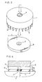
- FIGs. 1 through 4 show an apparatus for cutting a used ink ribbon R according to a first embodiment of the present invention.
- This cutting apparatus comprises a first base 1 having a disk-like shape and a size that can be held by the user.
- a core holder 3 is movably mounted in a bore 1a defined centrally of the first base 1 to act as a positioning member that extends into a center core 2 of the used ink ribbon R.
- the core holder 3 includes a bottom flange 3a engageable with an annular projection 1b formed at one end of the bore 1a.
- a plug 4 is screwed to the other end of the bore 1a.
- the bore 1a contains a compression spring 5 extending between the plug 4 and the bottom flange 3a of core holder 3 to urge the core holder 3 outwardly of the first base 1.
- the first base 1 includes a plurality of cutting blades 6 fixed to the face of the base 1 defining the annular projection 1b. These cutting blades 6 extend radially with respect to the axis of the core holder 3, and define cutting edges the length of which exceeds a winding radius L of the ink ribbon R.
- the cutting blades 6 have radially inward ends located slightly outwardly of outer peripheries of the core 2 of the ink ribbon R mounted in position, so that the cutting blades 6 are out of contact with the core 2 during a cutting operation.
- This construction is incapable of cutting several winds of the ink ribbon R adjacent the core 2.
- this portion of the ink ribbon R is not used for printing, and presents no problem even if left uncut.
- the core holder 3 in a natural state project to a greater extent as at D1 than an extent of projection D2 of the cutting blades 6. Consequently, the core holder 3 enters the core 2 before the cutting blades 6 contact a side face of the wound ink ribbon R to be cut.
- the extent of projection D2 of the cutting blades 6 is greater than a width D3 of the ink ribbon R.
- This cutting apparatus may be used for cutting ink ribbons having different widths.
- the core holder 3 of the first base 1 is aligned to the core 2 of the used ink ribbon R placed on a working table 7 which is one example of planar bases. Thereafter, the cutting blades 6 of the first base 1 are brought into contact with a side face of the wound ink ribbon R. In this state the user presses the first base 1 hard from behind with his or her hand. This causes the cutting blades 6 to cut transversely into the used ink ribbon R, whereby the ink ribbon R wound in a pancake form is shredded to small strips.
- a working mat formed of rubber or other elastic material is placed on the planar working table 7.
- the number, length and spacing of the cutting blades 6 may be selected according to the size of used ink ribbon R or a desired cutting width.
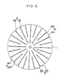
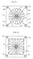
- the second embodiment as shown in Fig. 5, includes two types, one longer than the other, of cutting blades 6A and 6B arranged alternately in the peripheral direction. In this embodiment, therefore, the cutting blades are not densely arranged adjacent the center of the used ink ribbon R. This construction has the advantage of facilitating assembly of the cutting blades while allowing the ink ribbon R to be cut to desired widths.
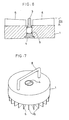
- Fig. 6 shows a third embodiment of the invention.
- the extent of projection D2 of the cutting blades 6 is uniform longitudinally of the cutting blades 6 so that the entire edges of cutting blades 6 simultaneously contact a side face of the used ink ribbon R.
- the cutting blades 6 are tapered with the extent of projection D2 increasing longitudinally outwardly of the cutting blades 6.
- Fig. 7 shows a fourth embodiment which includes a handle 8 fixed to the back face of the first base 1 as distinct from the first embodiment in which the entire first base 1 is held with a hand.
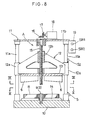
- Figs. 8 through 10 show an ink ribbon cutting apparatus according to a fifth embodiment of the invention.
- This cutting apparatus comprises a first base 10 including a ribbon holder 9 for removably holding a used ink ribbon R, and a frame 11 erected on the first base 10 and approximately gate-shaped in front view.
- the gate-shaped frame 11 includes four struts 11a for slidably supporting guide tubes 12a of a vertically movable slide frame 12.
- the slide frame 12 carries a second base 13 removably attached to a bottom surface thereof.
- the second base 13 includes radially extending cutting blades 6 secured to the face thereof opposed to the ribbon holder 9.
- This apparatus further comprises a cutting control section A for raising and lowering the second base 13 relative to the first base 10 and radially of the used ink ribbon R mounted on the ribbon holder 9.
- the ribbon holder 9 comprises a core holder 3 screwed to a central position of the first base 1 to act as a positioning member that extends into the center core 2 of the used ink ribbon R.
- the core holder 3 is interchangeable with different core holders to suit shapes of the core 2 of the used ink ribbon R.
- the first base 1 defines radial grooves 14 on a top surface thereof for receiving the cutting blades 6 descending with the second base 13 when cutting the used ink ribbon R.
- the cutting control section A includes a screw shaft 15 rotatable about a vertical axis and supported by a horizontal frame 11b supported on tops of the four struts 11a of the gate-shaped frame 11, and an electric motor 18 having a bevel gear 17 meshed with a bevel gear 16 attached to an upper end of the screw shaft 15.
- the screw shaft 15 has a male screw meshed with a female screw 12b of the slide frame 12.
- the electric motor 18 is rotatable forward and backward to vertically drive the slide frame 12.
- the gate-shaped frame 11 supports a control panel 19 including a starter switch SW1 and an emergency stop switch SW2 for controlling the electric motor 18.
- the gate-shaped frame 11 further supports a first sensor S1 such as a limit switch for detecting the slide frame 12 having descended to a position for completing ribbon cutting, and a second sensor S2 for detecting the slide frame 12 having ascended to a predetermined standby position.
- the electric motor 18 rotates forward to lower the slide frame 12. Then the cutting blades 6 movable with the slide frame 12 cut in from one face of the used ink ribbon R as held by the ribbon holder 9 of the first base 10. As a result, the ink ribbon R is cut transversely.
- the electric motor 18 rotates backward in response to a signal output from the first sensor S1, to automatically raise the slide frame 12.
- the electric motor 18 stops in response to a signal output from the second sensor S2.
- the electric motor 18 comprises a stepper motor
- the number of pulses for driving the stepper motor indicates the current position of the slide frame 12. Therefore, the sensors S1 and S2 may be dispensed with, and upper and lower limits of movement of the slide frame 12 may be varied freely in accordance with the type of the used ink ribbon R.
- the second base 13 may be constructed rotatable relative to the slide frame 12 for scattering cut ink ribbon pieces radially outwardly. Such a construction has the advantage of preventing leakage of secret information with increased reliability in that the cut ink ribbon pieces become mixed up.
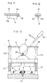
- Figs. 11 and 12 show a sixth embodiment which differs from the fifth embodiment in the attachment structure of the cutting blades 6.
- the second base 13 defines dovetail grooves 13a
- each of the cutting blades 6 includes a mounting portion 6a slidable into each dovetail groove 13a from a radially outward end thereof.
- a retainer ring 20 is removably screwed onto the second base 13 for stopping the cutting blades 6 from pulling out of the grooves 13a.
- This embodiment has an advantage of allowing the cutting blades 6 to be changed freely in accordance with the type of used ink ribbon R.
- Figs. 13 and 14 show a seventh embodiment which differs from the fifth embodiment in the cutting control section A.
- This embodiment includes compression springs 21 provided on the struts 11a of the gate-shaped frame 11 for upwardly urging the slide frame 12, and a control shaft 23 supported by the horizontal frame 11b of the gate-shaped frame 11 to be rotatable on a horizontal axis, the control shaft 23 carrying an eccentric cam 22 for contacting an upper surface of the slide frame 12.
- a control lever 24 is fixed to one end of the control shaft 23. When the control lever 24 is turned in the direction indicated by an arrow, the eccentric cam 21 is turned therewith to depress the slide frame 12. As a result, the cutting blades 6 cut the ink ribbon R in a pancake form to small pieces.
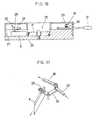
- Figs. 15 through 17 show an ink ribbon cutting apparatus according to an eighth embodiment of the invention.
- This apparatus comprises a base 26 including a ribbon holder 25 for removably holding a used ink ribbon R.
- the base 26 defines, on an upper surface thereof, grooves 27 extending radially with respect to the center of the ribbon holder 25.
- a cutting blade 6 is movably mounted in each groove 27.
- This cutting apparatus further comprises a cutting control section B for moving the cutting blades 6 radially of the ink ribbon R held by the ribbon holder 25. That is, the base 26 per se acts also as a positioning device to hold peripheries of the ink ribbon R in position.
- the cutting control section B includes operating arms 29 pivotably attached to the upper surface of the base 26, each arm 29 being approximately L-shaped in plan view and engageable with a pin 28 fixed to each cutting blade 6.
- An adjacent pair of operating arms 29 is pivotally interconnected through a rod 30.
- a control lever 31 is connected to one of the operating arms 29.
- a tension spring 32 extends between the control lever 31 and the base 26 for urging and retracting the cutting blades 6 radially outwardly to standby positions.
- Number 33 in the drawings indicates a cover removably attached to the base 26 for covering upper positions of the operating arms 29 and rod 30 as well as the cutting blades 6 in the standby positions.
- the foregoing embodiments are constructed to cut used ink ribbon R only.
- the present invention may be embodied such that the core 2 disposed centrally of the used ink ribbon R is cut at the same time.
- the force required for cutting the core may be greatly reduced by forming slits in cutting positions of the core 2 in advance.
- the present invention is of course applicable also to used ink ribbons having no core.
- the user manually places the ink ribbon R in position for the cutting operation and collects cut ribbon pieces.
- These operations may be carried out automatically by adding a ribbon mounting mechanism and a cut ribbon discharging mechanism.
- the cutting control sections A and B and ribbon holders 9 and 25 are not limited to the described constructions, but may be modified in many ways taking various conditions into account, such as types of the used ink ribbons R and working situations.
- the cutting blades 6 extend radially with respect to the center of the ink ribbon R. It is, however, not absolutely necessary to arrange radially with respect to the center of the ink ribbon. It will be sufficient if the cutting blades 6 on the whole are arranged approximately radially to be able to cut the ink ribbon.
Landscapes
- Impression-Transfer Materials And Handling Thereof (AREA)
- Nonmetal Cutting Devices (AREA)
Applications Claiming Priority (2)
| Application Number | Priority Date | Filing Date | Title |
|---|---|---|---|
| JP110952/88 | 1988-08-24 | ||
| JP1988110952U JPH0231767U (fr) | 1988-08-24 | 1988-08-24 |
Publications (2)
| Publication Number | Publication Date |
|---|---|
| EP0355824A2 true EP0355824A2 (fr) | 1990-02-28 |
| EP0355824A3 EP0355824A3 (fr) | 1990-09-19 |
Family
ID=14548699
Family Applications (1)
| Application Number | Title | Priority Date | Filing Date |
|---|---|---|---|
| EP19890115596 Ceased EP0355824A3 (fr) | 1988-08-24 | 1989-08-23 | Appareil de coupe pour ruban encreur usé |
Country Status (3)
| Country | Link |
|---|---|
| US (1) | US5018419A (fr) |
| EP (1) | EP0355824A3 (fr) |
| JP (1) | JPH0231767U (fr) |
Cited By (1)
| Publication number | Priority date | Publication date | Assignee | Title |
|---|---|---|---|---|
| EP2563599A4 (fr) * | 2010-04-26 | 2017-12-06 | Datacard Corporation | Procédé et dispositif pour destruction de ruban usagé |
Families Citing this family (5)
| Publication number | Priority date | Publication date | Assignee | Title |
|---|---|---|---|---|
| JPH04347692A (ja) * | 1991-05-27 | 1992-12-02 | Dainippon Printing Co Ltd | カラープリント用感熱転写フィルムの接合方法 |
| US6318225B1 (en) * | 1999-06-11 | 2001-11-20 | Ite, Inc. | Tortilla cutter |
| US7984667B2 (en) * | 2006-03-24 | 2011-07-26 | Quantum Technical Services Inc. | Pizza cutting apparatus |
| US8495941B2 (en) * | 2008-02-01 | 2013-07-30 | Tariq Farid | Sectioning device and method of use |
| US8555763B2 (en) * | 2008-02-01 | 2013-10-15 | Tariq Farid | Sectioning device and method of use |
Family Cites Families (10)
| Publication number | Priority date | Publication date | Assignee | Title |
|---|---|---|---|---|
| US880057A (en) * | 1907-05-04 | 1908-02-25 | Melley M Wheeler | Potato-cutter. |
| US2196619A (en) * | 1938-06-06 | 1940-04-09 | Andresen Halvor Tobi Heyerdahl | Machine for making closures |
| US3060838A (en) * | 1960-02-15 | 1962-10-30 | Priore Philip Nick | Super pie plate and cutter |
| US3190330A (en) * | 1963-05-20 | 1965-06-22 | Michael L Antos | Garnish cutter for fruit and vegetables |
| US3430290A (en) * | 1966-08-01 | 1969-03-04 | Phillips Petroleum Co | Apparatus for sealing and severing parisons |
| DE8019489U1 (de) * | 1980-07-19 | 1980-10-23 | Rekla, Norbert, 8947 Oberstaufen | Teilgeraet fuer pizzas |
| DE3135897C2 (de) * | 1981-09-10 | 1983-07-28 | Triumph-Adler Aktiengesellschaft für Büro- und Informationstechnik, 8500 Nürnberg | Vorrichtung für Schreibmaschinen zum Unlesbarmachen von verbrauchten Kohlebändern |
| US4436025A (en) * | 1983-04-01 | 1984-03-13 | Jones Frank W | Sectioning device for rounded food articles |
| DE3415691A1 (de) * | 1984-04-27 | 1985-10-31 | Reinhard 6361 Niddatal Napierski | Schneidvorrichtung zum kronenfoermigen schneiden von fruechten und dergleichen |
| DE3607503A1 (de) * | 1986-03-07 | 1987-10-01 | Schleicher Co Feinwerktech | Vorrichtung zum zerkleinern von baendern |
-
1988
- 1988-08-24 JP JP1988110952U patent/JPH0231767U/ja active Pending
-
1989
- 1989-08-22 US US07/397,173 patent/US5018419A/en not_active Expired - Fee Related
- 1989-08-23 EP EP19890115596 patent/EP0355824A3/fr not_active Ceased
Cited By (1)
| Publication number | Priority date | Publication date | Assignee | Title |
|---|---|---|---|---|
| EP2563599A4 (fr) * | 2010-04-26 | 2017-12-06 | Datacard Corporation | Procédé et dispositif pour destruction de ruban usagé |
Also Published As
| Publication number | Publication date |
|---|---|
| US5018419A (en) | 1991-05-28 |
| JPH0231767U (fr) | 1990-02-28 |
| EP0355824A3 (fr) | 1990-09-19 |
Similar Documents
| Publication | Publication Date | Title |
|---|---|---|
| EP0061776B1 (fr) | Dispositif pour imprimer et cassette y destinée | |
| US6098515A (en) | Rotary trimmer and blade biasing carriage assembly for use with a rotary trimmer | |
| DE69331725T2 (de) | Streifenkassette und Druckvorrichtung | |
| KR100287995B1 (ko) | 프린터 | |
| JP3523314B2 (ja) | ブレード組立体の製造方法及びブレード組立体 | |
| US4599125A (en) | Method and system for forming sheet material into apertured shapes | |
| US6339982B1 (en) | Cutting mechanism and a printing device with automatic cut | |
| EP1559566B9 (fr) | Imprimante d'étiquettes | |
| JPH0131479Y2 (fr) | ||
| EP0435108A2 (fr) | Cassette pour ruban d'écriture thermique | |
| US5018419A (en) | Used ink ribbon cutting apparatus | |
| JPH02145375A (ja) | サーマルプリンタ | |
| JPH09314938A (ja) | 切断装置 | |
| US4385959A (en) | Splicing tape dispenser-applicator | |
| JPH1044538A (ja) | 切断機構及び印刷装置 | |
| US4608110A (en) | Pressure sensitive label dispenser | |
| JP3470351B2 (ja) | カッタ装置 | |
| GB2313081A (en) | A printing device with automatic cut | |
| CN223479526U (zh) | 一种纸箱封箱贴胶带机 | |
| JP2005131717A (ja) | パターン又は画像を複数整列させたシートの切断方法及びその切断装置 | |
| CN219255672U (zh) | 一种连续冲切装置 | |
| JP2598505B2 (ja) | 電解コンデンサ素子巻回装置の撓み制御機構 | |
| JPH0131481Y2 (fr) | ||
| CN213950041U (zh) | 一种自动印刷机 | |
| JP2008080449A (ja) | 切断装置 |
Legal Events
| Date | Code | Title | Description |
|---|---|---|---|
| PUAI | Public reference made under article 153(3) epc to a published international application that has entered the european phase |
Free format text: ORIGINAL CODE: 0009012 |
|
| AK | Designated contracting states |
Kind code of ref document: A2 Designated state(s): AT CH DE FR GB IT LI NL |
|
| PUAL | Search report despatched |
Free format text: ORIGINAL CODE: 0009013 |
|
| AK | Designated contracting states |
Kind code of ref document: A3 Designated state(s): AT CH DE FR GB IT LI NL |
|
| 17P | Request for examination filed |
Effective date: 19900827 |
|
| 17Q | First examination report despatched |
Effective date: 19920918 |
|
| STAA | Information on the status of an ep patent application or granted ep patent |
Free format text: STATUS: THE APPLICATION HAS BEEN REFUSED |
|
| 18R | Application refused |
Effective date: 19930311 |