EP0355939A2 - Cartouche à ruban encreur - Google Patents
Cartouche à ruban encreur Download PDFInfo
- Publication number
- EP0355939A2 EP0355939A2 EP89250012A EP89250012A EP0355939A2 EP 0355939 A2 EP0355939 A2 EP 0355939A2 EP 89250012 A EP89250012 A EP 89250012A EP 89250012 A EP89250012 A EP 89250012A EP 0355939 A2 EP0355939 A2 EP 0355939A2
- Authority
- EP
- European Patent Office
- Prior art keywords
- support body
- cassette housing
- cassette
- barbs
- ribbon
- Prior art date
- Legal status (The legal status is an assumption and is not a legal conclusion. Google has not performed a legal analysis and makes no representation as to the accuracy of the status listed.)
- Granted
Links
Images
Classifications
-
- B—PERFORMING OPERATIONS; TRANSPORTING
- B41—PRINTING; LINING MACHINES; TYPEWRITERS; STAMPS
- B41J—TYPEWRITERS; SELECTIVE PRINTING MECHANISMS, i.e. MECHANISMS PRINTING OTHERWISE THAN FROM A FORME; CORRECTION OF TYPOGRAPHICAL ERRORS
- B41J17/00—Mechanisms for manipulating page-width impression-transfer material, e.g. carbon paper
- B41J17/32—Detachable carriers or holders for impression-transfer material mechanism
Definitions
- the invention relates to an ink ribbon cassette for an image recording device consisting of a cassette housing in which a printing roller and an ink ribbon stored on two winding spools axially parallel to the printing roller are arranged.
- an ink ribbon cassette for an image recording device designed as a parallel thermal transfer printer in which a line-shaped recording head is arranged within a printer housing.
- the ink ribbon cassette which can be inserted into the printer housing through a lateral opening in the direction along the recording head, contains a printing roller and an ink ribbon on two winding spools that are axially parallel to the printing roller in a cartridge housing. Since the print roller and the winding spools are integral parts of the ribbon cassette, the cassette housing and the print roller are automatically replaced each time the ribbon is changed.
- an ink ribbon cassette of the type specified at the outset is considered to be state of the art, in which the winding spools for the ink ribbon are held in two bearing bodies and together with them one in the cartridge housing insertable, interchangeable unit form, so that a ribbon change does not necessarily require an exchange of the entire ribbon cassette including the printing roller.
- the invention has for its object to enable a ribbon change that is particularly easy to carry out manually, without having to change the cassette housing together with the Print roller is required.
- this object is achieved in that the winding spools are held on a common support body in the ink ribbon cassette of the type mentioned, that the support body is removably arranged in the cassette housing and locked by means of a locking device and that at least one actuating element on the support body is arranged for simultaneously unlocking and removing the support body from the cassette housing.
- the main advantage of the ink ribbon cassette according to the invention is the simple interchangeability of the ink ribbon, wherein only one handle is required to remove the ink ribbon, with which the carrier body is unlocked in the cartridge housing and at the same time removed from it.
- the at least one actuating element serves as a grip element for holding the support body with the winding spools, so that touching the ink ribbon is excluded; this is particularly important in the case of generally very thin and therefore correspondingly sensitive thermal transfer ribbons.
- the carrier body consists of two side parts receiving the winding spools at their axial ends and a connecting part connecting the side parts with a recess for the printing roller, an actuating element being arranged on each of the side parts. Due to the arrangement of the actuating elements on both sides, the support body with the winding spools can be easily removed with both hands from the cassette housing.
- the cassette housing consists of a substantially cuboid one-sided open box, the open side of which is closed by the connecting part of the carrier body when the carrier body is inserted so that touching the ribbon on the winding spools is prevented when handling the ribbon cassette.
- a secure and correct locking of the support body with the winding spools in the cassette housing is advantageously made possible in that the pressure roller is mounted in the cassette housing between two mounting parts on which the locking parts forming barbed parts are held with barbs at their ends, and that at the Side parts of the support body in shoulder-ending ramp surfaces for the barbs are designed in such a way that when the support body is inserted into the cassette housing, the bent parts are deflected and the barbs spring back behind the heels in the locking position.
- the run-up surfaces additionally serve in cooperation with the barbs attached to them as a guide when inserting the support body into the cassette housing, so that damage to the ink ribbon on the winding spools is avoided, for example by tilting the support body.
- the actuating elements are preferably designed in the form of bending elements which have ends at the ends opposite the barbs and can be moved in the direction of the barbs in the sense of their unlocking. Due to their design as bending elements, the actuating elements can advantageously be connected in one piece to the support body in the form of plastic injection molded parts.
- the ribbon cassette In connection with the design of the actuating elements in the form of bending elements, according to a preferred development of the ribbon cassette according to the invention it is provided that two bending elements are arranged on both side parts of the support body perpendicular to the direction of removal of the support body from the cassette housing.
- the opposite bending elements can be gripped and pressed together on both sides of the support body with thumb and forefinger, whereby the Unlocking the support body and holding it securely and conveniently with both hands between thumb and index finger for removal from the cassette housing.
- Another advantage of this development is the fact that only an approximately finger-wide gap is required between the side parts of the support body and the inner walls of the cassette housing opposite them in order to allow access to the actuating elements (bending elements).
- the locking device in the form of bent parts with barbs in connection with the design of the actuating elements as bending elements for pushing back the barbs, it is possible to form the actuating elements (bending elements) on the supporting body as close as possible to its connecting part, so that the actuating elements can be gripped does not have to be reached deep into the gap between the side parts of the support body and the inner walls of the cassette housing; the gap can therefore be made correspondingly narrow.
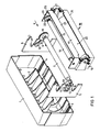
- FIG. 1 shows an exemplary embodiment of the ink ribbon cassette according to the invention, the essential components of which are shown here separately from one another for the sake of clarity.
- the ribbon cassette is closed to the outside by a cassette housing 1, which consists essentially of a cuboid, open to one side box.
- a cassette housing 1 Within the cassette housing 1, rib-shaped, curved guide elements 2 are formed which, as will be explained in more detail below, serve to guide a recording sheet to be printed.
- the cassette housing 1 has grooves 3 and 4 on its lower inner wall delimited by guide ribs for receiving two holding parts 5 and 6, between which a pressure roller 7 is rotatably mounted.
- the pressure roller 7 is connected in the region of its bearing in the holding part designated 6 with a drive gear 8 which meshes with two further gears 9 and 10.
- the two mounting parts 5 and 6 have on their sides facing the inner walls of the cassette housing 1 elastic bent parts with barbs at their ends, of which in FIG. 1 the bent parts 11 and 12 with their barbs 13 and 14 are only visible on the mounting part 5.
- the mounting parts 5 and 6 for the printing roller 7 are shown outside of the cassette housing 1 only for the sake of clarity; in fact, however, they are fitted in grooves 3 and 4.
- an ink ribbon is stored on two winding spools 16 and 17, which are held on a common support body 18 parallel to one another.
- the support body 18 consists of two side parts 19 and 20, which take up the winding coils 16 and 17 at their axial ends, and are connected to one another via a connecting part 21.
- the support body 18 forms, together with the winding spools 16 and 17, an exchangeable unit which can be inserted into the cassette housing 1 of the ink ribbon cassette, the printing roller 7, in the inserted state, being partially wrapped around the section of the ink ribbon 15 lying between the winding spools 16 and 17 from a recess 22 in protrudes from the connecting part 21 and a gear 23 connected to the winding spool 16 via a slip clutch meshes with the gear 10 on the holding part 6.
- the complete ribbon cassette can be plugged into a printer (not shown here), the printing roller 7 with the adjacent ink ribbon 15 coming to rest on a line-shaped recording head, for example a thermal printing head, which extends along the printing roller 7.
- the carrier body 18 with the winding spools 16 and 17 can be inserted into or removed from the cassette housing 1 of the ink ribbon cassette.
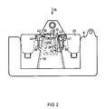
- FIG. 2 attaches the supporting body 18 shows on the bracket parts 5 and 6 in side view from the viewing direction designated X in Figure 1.
- the pressure roller 7 and the winding spools 16 and 17 are omitted in FIG. 2, so that only the side part 20 of the support body 18 and the holder part 6 are visible.
- the side part designated 19 in FIG. 1 and the holding part 5 are constructed in the same way as parts 20 and 6.
- FIG. 2 shows, two parallel bent parts 28 and 29 are held on the holding part 6, which are provided at their ends with barbs 30 and 31 facing away from one another and pointing outwards.
- the bent parts 28 and 29 are integrally formed on a plastic body 32 which in turn is fastened to the holding part 6.
- Each of the two side parts 19 and 20 of the support body 18 - here the side part 20 - has two contact surfaces 33 and 34 for the barbs 30 and 31 on the bent parts 28 and 29.
- the ramp surfaces 33 and 34 form in the direction designated 35 for the insertion of the support body 18 in the cassette housing 1 a funnel-shaped extension and end in the opposite direction with the formation of paragraphs 36 and 37, so that when inserting the support body 18 in the cassette housing 1 Barbs 30 and 31 slide along the run-up surfaces 33 and 34, the bent parts 28 and 29 being increasingly deflected and finally the barbs 30 and 31 snap into a locking position engaging behind the shoulders 36 and 37.
- This locked state is shown in Figure 2.
- the contact surfaces 33 and 34 in cooperation with the barbs 30 and 31 resiliently attached to them, serve as a guide when inserting the support body 18 into the cassette housing 1, thereby preventing the support body from tilting and possibly damaging the ink ribbon 15.
- FIG. 2 also shows using the example of the side part 20, the actuating elements 25 and 26 on the two side parts 19 and 20 each consist of two mutually opposite bending elements 38 and 39, which are molded onto the side part 20 made of plastic.
- the two bends elements 38 and 39 formed in such a way on the side part 20 that they can be gripped and pressed against one another at the outside grip points 40 and 41 with the thumb and forefinger of one hand, the barbs 30 and 31 opposite approaches 42 and 43 of the bending elements 38 and 39 are pushed over the paragraphs 36 and 37, pushing back the barbs 30 and 31.
- the support body 18 can thus be unlocked and removed from the cassette housing 1 in a simple manner by pressing the opposite bending elements on both sides of the support body 18 with thumb and forefinger, the support body 18 being unlocked and simultaneously with both hands is held securely and conveniently in each case between the thumb and index finger for removal from the cassette housing 1. It is for secure gripping of the actuators 26 and 27 or the bending elements forming them z. B. 38 and 39 only an approximately finger-wide gap between the side parts 19 and 20 of the support body and the inner wall of the cassette housing 1 is required, so that a compact structure of the ribbon cassette is achieved.
Landscapes
- Impression-Transfer Materials And Handling Thereof (AREA)
Applications Claiming Priority (2)
| Application Number | Priority Date | Filing Date | Title |
|---|---|---|---|
| DE3829445A DE3829445A1 (de) | 1988-08-26 | 1988-08-26 | Farbbandkassette |
| DE3829445 | 1988-08-26 |
Publications (3)
| Publication Number | Publication Date |
|---|---|
| EP0355939A2 true EP0355939A2 (fr) | 1990-02-28 |
| EP0355939A3 EP0355939A3 (en) | 1990-05-09 |
| EP0355939B1 EP0355939B1 (fr) | 1993-01-20 |
Family
ID=6361917
Family Applications (1)
| Application Number | Title | Priority Date | Filing Date |
|---|---|---|---|
| EP89250012A Expired - Lifetime EP0355939B1 (fr) | 1988-08-26 | 1989-08-04 | Cartouche à ruban encreur |
Country Status (3)
| Country | Link |
|---|---|
| US (1) | US5011310A (fr) |
| EP (1) | EP0355939B1 (fr) |
| DE (2) | DE3829445A1 (fr) |
Cited By (3)
| Publication number | Priority date | Publication date | Assignee | Title |
|---|---|---|---|---|
| EP0488291A1 (fr) * | 1990-11-29 | 1992-06-03 | Canon Kabushiki Kaisha | Cassette pour ruban encreur et appareil d'enregistrement l'utilisant |
| EP0679524A1 (fr) * | 1994-04-29 | 1995-11-02 | Agfa-Gevaert N.V. | Boîte de stockage d'une cassette pour une imprimante thermique |
| DE4433892B4 (de) * | 1993-09-22 | 2006-06-29 | Pentax Corp. | Zeilendrucker mit einem Thermo-Zeilendruckkopf |
Families Citing this family (7)
| Publication number | Priority date | Publication date | Assignee | Title |
|---|---|---|---|---|
| USD327088S (en) | 1989-04-28 | 1992-06-16 | Kyocera Corporation | Drum cartridge for a printer |
| JPH04126276A (ja) * | 1989-07-21 | 1992-04-27 | Canon Inc | インクシートカートリツジ及び前記インクシートカートリツジを装填可能な記録装置 |
| DE4035598A1 (de) * | 1990-11-06 | 1992-05-07 | Siemens Ag | Farbbandvorratseinrichtung |
| DE4117798A1 (de) * | 1991-05-30 | 1992-12-03 | Mannesmann Ag | Farbbandkassette |
| IE69331B1 (en) * | 1992-02-25 | 1996-10-16 | Balmaha Ltd | A Printer |
| US5447380A (en) * | 1992-06-01 | 1995-09-05 | Nai Technologies, Inc. | Thermal printer |
| US5769548A (en) * | 1996-10-07 | 1998-06-23 | Illinois Tool Works Inc. | Hot stamp imprinting system with latchable ink ribbon cassette & handle |
Family Cites Families (7)
| Publication number | Priority date | Publication date | Assignee | Title |
|---|---|---|---|---|
| US4493573A (en) * | 1982-03-19 | 1985-01-15 | Ricoh Company, Ltd. | Printing apparatus |
| JPH07106657B2 (ja) * | 1984-05-15 | 1995-11-15 | 株式会社東芝 | リボン収納カセット |
| US4702631A (en) * | 1984-11-08 | 1987-10-27 | Kabushiki Kaisha Toshiba | Thermal ribbon cassette and housing therefore |
| NL8501540A (nl) * | 1985-05-30 | 1986-12-16 | Philips Nv | Multifunctionele cassette voor een drukker. |
| US4673304A (en) * | 1985-08-13 | 1987-06-16 | Sanders Associates, Inc. | Thermal printer ribbon cartridge for wide ribbons |
| JPH061823Y2 (ja) * | 1986-04-11 | 1994-01-19 | 三菱電機株式会社 | 印字装置 |
| DE3721231A1 (de) * | 1987-06-24 | 1989-01-05 | Siemens Ag | Vorrichtung zum aufzeichnen von bildinformationen auf einem aufzeichnungsblatt |
-
1988
- 1988-08-26 DE DE3829445A patent/DE3829445A1/de not_active Withdrawn
-
1989
- 1989-08-04 DE DE8989250012T patent/DE58903333D1/de not_active Expired - Fee Related
- 1989-08-04 EP EP89250012A patent/EP0355939B1/fr not_active Expired - Lifetime
- 1989-08-22 US US07/396,924 patent/US5011310A/en not_active Expired - Fee Related
Cited By (4)
| Publication number | Priority date | Publication date | Assignee | Title |
|---|---|---|---|---|
| EP0488291A1 (fr) * | 1990-11-29 | 1992-06-03 | Canon Kabushiki Kaisha | Cassette pour ruban encreur et appareil d'enregistrement l'utilisant |
| US5800084A (en) * | 1990-11-29 | 1998-09-01 | Canon Kabushiki Kaisha | Ink sheet cartridge and recording apparatus using the ink sheet cartridge |
| DE4433892B4 (de) * | 1993-09-22 | 2006-06-29 | Pentax Corp. | Zeilendrucker mit einem Thermo-Zeilendruckkopf |
| EP0679524A1 (fr) * | 1994-04-29 | 1995-11-02 | Agfa-Gevaert N.V. | Boîte de stockage d'une cassette pour une imprimante thermique |
Also Published As
| Publication number | Publication date |
|---|---|
| EP0355939B1 (fr) | 1993-01-20 |
| EP0355939A3 (en) | 1990-05-09 |
| US5011310A (en) | 1991-04-30 |
| DE3829445A1 (de) | 1990-03-01 |
| DE58903333D1 (de) | 1993-03-04 |
Similar Documents
| Publication | Publication Date | Title |
|---|---|---|
| EP0313720B1 (fr) | Dispositif à main pour transférer un film d'une feuille porteuse sur un substrat | |
| DE19635587B4 (de) | Handgerät zum Übertragen eines Filmes aus z. B.klebendem, deckendem oder farbigem Material von einem auf einer Vorratsspule aufgewickelten Trägerband auf ein Substrat | |
| DE69325878T2 (de) | Vorrichtung zum Laden des farbstoffgebenden Elementes in einem Thermodrucker | |
| DE4433892B4 (de) | Zeilendrucker mit einem Thermo-Zeilendruckkopf | |
| EP0575790A1 (fr) | Dispositif d'application d'un film de matière adhésive sur un support | |
| EP0355939B1 (fr) | Cartouche à ruban encreur | |
| EP0297025B1 (fr) | Dispositif d'enregistrement à partir d'un écran sur un support d'informations | |
| DE3226510C2 (de) | Universelle Papiertransporteinrichtung für Einzelblätter und Endlospapier in Zeilendruckeinrichtungen | |
| EP0019649B1 (fr) | Mécanisme et cassette pour des rubans encreurs | |
| DE2247926C2 (de) | Kassette für ein Typenträgerband einer Druckmaschine | |
| DE3300458A1 (de) | Drucker mit automatischem papiereinzug | |
| DE69302840T2 (de) | Verfahren zum Anbringen eines Farbbandes in einem Kassettengehäuse und Farbbandkassette dazu anwendbar | |
| EP0149964A1 (fr) | Cartouche de ruban encreur | |
| DE19548442C2 (de) | Papierzuführvorrichtung | |
| DE2841216C3 (de) | Kassette für Registrierstreifen | |
| DE60023994T2 (de) | Druckvorrichtung und Anordnung mit einer zum Drucken verwendbaren Spule und einem auf die Spule bezogenen Informationsträger | |
| DE2253673C3 (de) | Vorrichtung zur Aufnahme einer eine Vorratsspule lagernden Vorratskassette oder einer kassettenlosen Vorratsspule für Farbbänder in Schreib- oder ähnlichen Maschinen | |
| DE2124230A1 (de) | Vorrichtung zum Transportieren und Stapeln von blattförmigen Aufzeichnungsträgern | |
| DE2000910A1 (de) | Taschenregister fuer handschriftliche Aufzeichnungen | |
| DE2543376C3 (de) | Farbbandwechsler für eine Mehrfarben-Schreibeinrichtung | |
| DE2930127C2 (fr) | ||
| EP0249159A2 (fr) | Cassette à ruban encreur pour machines à écrire ou autres machines de bureau | |
| DE1953161C3 (fr) | ||
| DE3033572C1 (de) | Vorrichtung zur Aufnahme einer Tintenrolle | |
| DE3214639C2 (de) | Vorrichtung zur Halterung einer Papierrolle mit mehrlagigem Papier in Druck- oder Schreibeinrichtungen |
Legal Events
| Date | Code | Title | Description |
|---|---|---|---|
| PUAI | Public reference made under article 153(3) epc to a published international application that has entered the european phase |
Free format text: ORIGINAL CODE: 0009012 |
|
| AK | Designated contracting states |
Kind code of ref document: A2 Designated state(s): CH DE FR GB IT LI NL |
|
| PUAL | Search report despatched |
Free format text: ORIGINAL CODE: 0009013 |
|
| AK | Designated contracting states |
Kind code of ref document: A3 Designated state(s): CH DE FR GB IT LI NL |
|
| 17P | Request for examination filed |
Effective date: 19901026 |
|
| 17Q | First examination report despatched |
Effective date: 19920421 |
|
| GRAA | (expected) grant |
Free format text: ORIGINAL CODE: 0009210 |
|
| AK | Designated contracting states |
Kind code of ref document: B1 Designated state(s): CH DE FR GB IT LI NL |
|
| PG25 | Lapsed in a contracting state [announced via postgrant information from national office to epo] |
Ref country code: IT Free format text: LAPSE BECAUSE OF FAILURE TO SUBMIT A TRANSLATION OF THE DESCRIPTION OR TO PAY THE FEE WITHIN THE PRE;WARNING: LAPSES OF ITALIAN PATENTS WITH EFFECTIVE DATE BEFORE 2007 MAY HAVE OCCURRED AT ANY TIME BEFORE 2007. THE CORRECT EFFECTIVE DATE MAY BE DIFFERENT FROM THE ONE RECORDED.SCRIBED TIME-LIMIT Effective date: 19930120 Ref country code: NL Effective date: 19930120 Ref country code: GB Effective date: 19930120 |
|
| REF | Corresponds to: |
Ref document number: 58903333 Country of ref document: DE Date of ref document: 19930304 |
|
| ET | Fr: translation filed | ||
| NLV1 | Nl: lapsed or annulled due to failure to fulfill the requirements of art. 29p and 29m of the patents act | ||
| GBV | Gb: ep patent (uk) treated as always having been void in accordance with gb section 77(7)/1977 [no translation filed] |
Effective date: 19930120 |
|
| PGFP | Annual fee paid to national office [announced via postgrant information from national office to epo] |
Ref country code: FR Payment date: 19930819 Year of fee payment: 5 |
|
| PGFP | Annual fee paid to national office [announced via postgrant information from national office to epo] |
Ref country code: DE Payment date: 19931020 Year of fee payment: 5 |
|
| PGFP | Annual fee paid to national office [announced via postgrant information from national office to epo] |
Ref country code: CH Payment date: 19931116 Year of fee payment: 5 |
|
| PLBE | No opposition filed within time limit |
Free format text: ORIGINAL CODE: 0009261 |
|
| STAA | Information on the status of an ep patent application or granted ep patent |
Free format text: STATUS: NO OPPOSITION FILED WITHIN TIME LIMIT |
|
| 26N | No opposition filed | ||
| PG25 | Lapsed in a contracting state [announced via postgrant information from national office to epo] |
Ref country code: LI Effective date: 19940831 Ref country code: CH Effective date: 19940831 |
|
| PG25 | Lapsed in a contracting state [announced via postgrant information from national office to epo] |
Ref country code: FR Effective date: 19950428 |
|
| REG | Reference to a national code |
Ref country code: CH Ref legal event code: PL |
|
| PG25 | Lapsed in a contracting state [announced via postgrant information from national office to epo] |
Ref country code: DE Effective date: 19950503 |
|
| REG | Reference to a national code |
Ref country code: FR Ref legal event code: ST |