EP0355945A2 - Verringerung der Verformung von stereolithografischen Teilen durch Isolierung der Spannungen - Google Patents
Verringerung der Verformung von stereolithografischen Teilen durch Isolierung der Spannungen Download PDFInfo
- Publication number
- EP0355945A2 EP0355945A2 EP89303785A EP89303785A EP0355945A2 EP 0355945 A2 EP0355945 A2 EP 0355945A2 EP 89303785 A EP89303785 A EP 89303785A EP 89303785 A EP89303785 A EP 89303785A EP 0355945 A2 EP0355945 A2 EP 0355945A2
- Authority
- EP
- European Patent Office
- Prior art keywords
- smalleys
- data
- stress
- layer
- set forth
- Prior art date
- Legal status (The legal status is an assumption and is not a legal conclusion. Google has not performed a legal analysis and makes no representation as to the accuracy of the status listed.)
- Granted
Links
Images


Classifications
-
- B—PERFORMING OPERATIONS; TRANSPORTING
- B29—WORKING OF PLASTICS; WORKING OF SUBSTANCES IN A PLASTIC STATE IN GENERAL
- B29C—SHAPING OR JOINING OF PLASTICS; SHAPING OF MATERIAL IN A PLASTIC STATE, NOT OTHERWISE PROVIDED FOR; AFTER-TREATMENT OF THE SHAPED PRODUCTS, e.g. REPAIRING
- B29C64/00—Additive manufacturing, i.e. manufacturing of three-dimensional [3D] objects by additive deposition, additive agglomeration or additive layering, e.g. by 3D printing, stereolithography or selective laser sintering
- B29C64/10—Processes of additive manufacturing
- B29C64/106—Processes of additive manufacturing using only liquids or viscous materials, e.g. depositing a continuous bead of viscous material
- B29C64/124—Processes of additive manufacturing using only liquids or viscous materials, e.g. depositing a continuous bead of viscous material using layers of liquid which are selectively solidified
- B29C64/129—Processes of additive manufacturing using only liquids or viscous materials, e.g. depositing a continuous bead of viscous material using layers of liquid which are selectively solidified characterised by the energy source therefor, e.g. by global irradiation combined with a mask
- B29C64/135—Processes of additive manufacturing using only liquids or viscous materials, e.g. depositing a continuous bead of viscous material using layers of liquid which are selectively solidified characterised by the energy source therefor, e.g. by global irradiation combined with a mask the energy source being concentrated, e.g. scanning lasers or focused light sources
-
- B—PERFORMING OPERATIONS; TRANSPORTING
- B29—WORKING OF PLASTICS; WORKING OF SUBSTANCES IN A PLASTIC STATE IN GENERAL
- B29C—SHAPING OR JOINING OF PLASTICS; SHAPING OF MATERIAL IN A PLASTIC STATE, NOT OTHERWISE PROVIDED FOR; AFTER-TREATMENT OF THE SHAPED PRODUCTS, e.g. REPAIRING
- B29C67/00—Shaping techniques not covered by groups B29C39/00 - B29C65/00, B29C70/00 or B29C73/00
- B29C67/24—Shaping techniques not covered by groups B29C39/00 - B29C65/00, B29C70/00 or B29C73/00 characterised by the choice of material
-
- B—PERFORMING OPERATIONS; TRANSPORTING
- B33—ADDITIVE MANUFACTURING TECHNOLOGY
- B33Y—ADDITIVE MANUFACTURING, i.e. MANUFACTURING OF THREE-DIMENSIONAL [3D] OBJECTS BY ADDITIVE DEPOSITION, ADDITIVE AGGLOMERATION OR ADDITIVE LAYERING, e.g. BY 3D PRINTING, STEREOLITHOGRAPHY OR SELECTIVE LASER SINTERING
- B33Y10/00—Processes of additive manufacturing
-
- G—PHYSICS
- G05—CONTROLLING; REGULATING
- G05B—CONTROL OR REGULATING SYSTEMS IN GENERAL; FUNCTIONAL ELEMENTS OF SUCH SYSTEMS; MONITORING OR TESTING ARRANGEMENTS FOR SUCH SYSTEMS OR ELEMENTS
- G05B2219/00—Program-control systems
- G05B2219/30—Nc systems
- G05B2219/49—Nc machine tool, till multiple
- G05B2219/49013—Deposit layers, cured by scanning laser, stereo lithography SLA, prototyping
-
- Y—GENERAL TAGGING OF NEW TECHNOLOGICAL DEVELOPMENTS; GENERAL TAGGING OF CROSS-SECTIONAL TECHNOLOGIES SPANNING OVER SEVERAL SECTIONS OF THE IPC; TECHNICAL SUBJECTS COVERED BY FORMER USPC CROSS-REFERENCE ART COLLECTIONS [XRACs] AND DIGESTS
- Y02—TECHNOLOGIES OR APPLICATIONS FOR MITIGATION OR ADAPTATION AGAINST CLIMATE CHANGE
- Y02P—CLIMATE CHANGE MITIGATION TECHNOLOGIES IN THE PRODUCTION OR PROCESSING OF GOODS
- Y02P90/00—Enabling technologies with a potential contribution to greenhouse gas [GHG] emissions mitigation
- Y02P90/80—Management or planning
Definitions
- This invention relates generally to improvements in methods and apparatus for forming three-dimensional objects from a fluid medium and, more particularly- to a new and improved stereolithography system involving the application of enhanced data manipulation and lithographic techniques to production of three-dimensional objects, whereby such objects can be formed more rapidly, reliably, accurately and economically.
- this invention relates to reducing stereo-lithographic distortion of the object by isolating stress.
- stereolithography is a method for automatically building complex plastic parts by successively printing cross-sections of photopolymer (such as liquid plastic) on top of each other until all of the thin layers are joined together to form a whole part.
- photopolymer such as liquid plastic
- Photocurable polymers change from liquid to solid in the presence of light and their photospeed with ultraviolet light (UV) is fast enough to make them practical model building materials.
- the material that is not polymerized when a part is made is still usable and remains in the vat as successive parts are made.
- An ultraviolet laser generates a small intense spot of UV. This spot is moved across the liquid surface with a galvanometer mirror XY scanner. The scanner is driven by computer generated vectors or the like. Precise complex patterns can be rapidly produced with this technique.
- SLA stereolithography apparatus
- Stereolithography represents an unprecedented way to quickly make complex or simple parts without tooling. Since this technology depends on using a computer to generate its cross sectional patterns, there is a natural data link to CAD/CAM. However, such systems have encountered difficulties relating to shrinkage, curl and other distortions, as well as resolution, accuracy and difficulties in producing certain object shapes.
- Objects built using stereolithography have a tendency to distort from their CAD designed dimensions. This distortion may or may not appear in a specific object, based on how much stress is developed by the specific cure parameters and on the object's ability to withstand stress.
- the stress that causes distortion develops when material that is being converted from liquid to solid comes into contact with and bonds to previously cured material. When material is converted from liquid to solid it shrinks slightly. This shrinking causes stress and has two primary physical causes: 1) density of the liquid is less than that of the solid plastic; and 2) the chemical reaction that causes the change of state is strongly exothermic causing the curing material to thermally expand and contract. This stress causes a distortion known as curl, which is described in more detail in S.N. 182,823.
- the boundary vectors may have moved away from their proper positions and, therefore, may not be secured at particular locations. These unsecured boundaries can move up and down and give a rough surface finish to the object, similar to a bird's nest.
- the present invention provides a new and improved stereolithography system for generating a-three-dimensional object by forming successive, adjacent, cross-sectional laminae of that object at the face of a fluid medium capable of altering its physical state in response to appropriate synergistic stimulation, information defining the object being specially tailored to reduce curl, stress, birdnesting and other distortions, the successive laminae being automatically integrated as they are formed to define the desired three-dimensional object.
- distortion is reduced by isolating sections of an object so that stress cannot be transmitted from one section to another.
- This isolation technique (Smalleys) limits the distortion in a given section to that which can be caused by the stress developed within that section only, not from other sections.
- Layer sections prone to curling may be isolated by designing small holes or gaps at stress points in the CAD design of the part. These gaps, called “Smalleys", block propagation of stresses along layer sections. This reduces the stresses acting on a part to only those created within the section. If the Smalleys are properly designed, these localized stresses will be below the threshold value which would curl the layer section.
- Smalleys are also used to reduce birdnesting.
- the width of Smalleys is generally less than cure width, so that after curing they are completely filled in and so no structural integrity is lost through their use.
- Smalleys are placed periodically in regions of down-facing near-flat triangles with heights appropriate to extend vertically through the near-flat triangles. The placement of Smalleys is based on several factors that affect the likelihood of having birdnesting problems: the radius of curvature of the boundaries, the length of near-flat zones, the likelihood of boundaries moving, etc. Smalleys do not need to penetrate completely through a wall, as they do in their other application, but they do need to penetrate deep enough to insure a contact point with the boundaries on the previous layer.
- the present invention harnesses the principles of computer generated graphics in combination with stereolithography, i.e., the application of lithographic techniques to the production of three-dimensional objects, to simultaneously execute computer aided design (CAD) and computer aided manufacturing (CAM) in producing three-dimensional objects directly from computer instructions.
- CAD computer aided design
- CAM computer aided manufacturing
- the invention can be applied for the purposes of sculpturing models and prototypes in a design phase of product development, or as a manufacturing system, or even as a pure art form.
- Stepolithography is a method and apparatus for making solid objects by successively “printing” thin layers of a curable material, e.g., a UV curable material, one on top of the other.
- a curable material e.g., a UV curable material
- a programmed movable spot beam of UV light shining on a surface or layer of UV curable liquid is used to form a solid cross-section of the object at the surface of the liquid.
- the object is then moved, in a programmed manner, away from the liquid surface by the thickness of one layer, and the next cross-section is then formed and adhered to the immediately preceding layer defining the object. This process is continued until the entire object is formed.
- a body of a fluid medium capable of solidification in response to prescribed stimulation is first appropriately contained in any suitable vessel to define a designated working surface of the fluid medium at which successive cross-sectional laminae can be generated.
- an appropriate form of synergistic stimulation such as a spot of UV light or the like, is applied as a graphic pattern at the specified working surface of the fluid medium to form thin, solid, individual layers at the surface, each layer representing an adjacent cross-section of the three-dimensional object to be produced.
- information defining the object is specially processed to reduce curl and distortion, and increase resolution, strength, accuracy, speed and economy of reproduction.
- Superposition of successive adjacent layers on each other is automatically accomplished, as they are formed, to integrate the layers and define the desired three-dimensional object.
- a suitable platform to which the first lamina is secured is moved away from the working surface in a programmed manner by any appropriate actuator, typically all under the control of a micro computer or the like. In this way, the solid material that was initially formed at the working surface is moved away from that surface and new liquid flows into the working surface position.
- this new liquid is, in turn, converted to solid material by the programmed UV light spot to define a new lamina, and this new lamina adhesively connects to the material adjacent to it, i.e., the immediately preceding lamina. This process continues until the entire three-dimensional object has been formed. The formed object is then removed from the container and the apparatus is ready to produce another object, either identical to the first object or an entirely new object generated by a computer or the like.
- the data base of a CAD system can take several forms.
- One form consists of representing the surface of an object as a mesh of polygons, typically triangles. These triangles completely form the inner and outer surfaces of the object.
- This CAD representation also includes a unit length normal vector for each triangle. The normal points away from the solid which the triangle is bounding and indicates slope.
- Means are provided for processing CAD data, which may be in the form of "PHIGS" or the like, into layer-by-layer vector data that can be used for forming models through stereolithography. Such information may ultimately be converted to raster scan output data or the like.
- stereolithography is a three-dimensional printing process which uses a moving laser beam to build parts by solidifying successive layers of liquid plastic. This method enables a designer to create a design on a CAD system, applying the concepts of this invention, to reduce curl, stress, birdnesting and other distortions and build an accurate plastic model in a few hours.
- a stereolithographic process may include the following steps.
- the solid model is designed in the normal way on the CAD system, without specific reference to the stereolithographic process.
- Model preparation for stereolithography involves selecting the optimum orientation, adding supports, building in appropriate stress relief, and selecting the operating parameters of the stereolithography system.
- the optimum orientation will (1) enable the object to drain, (2) have the least number of unsupported surfaces, (3) optimize important surfaces, and (4) enable the object to fit in the resin vat. Supports must be added to secure unattached sections and for other purposes, and a CAD library of supports can be prepared for this purpose.
- the stereolithography operating parameters include selection of the model scale and layer (slice) thickness.
- the surface of the solid model is then divided into triangles, typically "PHIGS".
- a triangle is the least complex polygon for vector calculations. The more triangles formed, the better the surface resolution and hence, the more accurate the formed object with respect to the CAD design.
- Data points representing the triangle coordinates and normals thereto are then transmitted typically as PHIGS, to the stereolithographic system via appropriate network communication such as ETHERNET.
- the software of the stereolithographic system then slices the triangular sections horizontally (XY plane) at the selected layer thickness.
- the stereolithographic unit next calculates the section boundary, hatch, and horizontal surface (skin) vectors.
- Hatch vectors consist of cross-hatching between the boundary vectors. Several "styles" or slicing formats are available. Skin vectors, which are traced at high speed and with a large overlap, form the outside horizontal surfaces of the object. Interior horizontal areas, those within top and bottom skins, are not filled in other than by cross-hatch vectors.
- the SLA then forms the object one horizontal layer at a time by moving the ultraviolet beam of a helium-cadmium laser or the like across the surface of a photocurable resin and solidifying the liquid where it strikes. Absorption in the resin prevents the laser light from penetrating deeply and allows a thin layer to be formed.
- Each layer is comprised of vectors which are typically drawn in the following order: border, hatch, and surface.
- the first layer that is drawn by the SLA adheres to a horizontal platform located just below the liquid surface.
- This platform is attached to an elevator which then lowers the elevator under computer control.
- the platform dips a short distance, such as several millimeters into the liquid to coat the previous cured layer with fresh liquid, then rises, up a smaller distance leaving a thin film of liquid from which the second layer will be formed.
- the next layer is drawn. Since the resin has adhesive properties, the second layer becomes firmly attached to the first. This process is repeated until all the layers have been drawn and the entire three-dimensional object is formed. Normally, the bottom 0.25 inch or so of the object is a support structure on which the desired part is built. Resin that has not been exposed to light remains in the vat to be used for the next part. There is very little waste of material.
- Post processing typically involves draining the formed object to remove excess resin, ultraviolet or heat curing to complete polymerization, and removing supports. Additional processing, including sanding and assembly into working models, may also be performed.
- the new and improved stereolithographic system of the present invention has many advantages over currently used apparatus for producing plastic objects.
- the methods and apparatus of the present invention avoid the need of producing design layouts and drawings, and of producing tooling drawings and tooling.
- the designer can work directly with the computer and a stereolithographic device, and when he is satisfied with the design as displayed on the output screen of the computer, he can fabricate a part for direct examination. If the design has to be modified, it can be easily done through the computer, and then another part can be made to verify that the change was correct. If the design calls for several parts with interacting design parameters, the method of the invention becomes even more useful because of all of the part designs can be quickly changed and made again so that the total assembly can be made and examined, repeatedly if necessary.
- the data manipulation techniques of the present invention enable production of objects with reduced stress, curl and distortion, and increased resolution, strength accuracy, speed and economy of production, even for difficult and complex object shapes.
- stereolithography is particularly useful for short run production because the need for tooling is eliminated and production set-up time is minimal. Likewise, design changes and custom parts are easily provided using the technique. Because of the ease of making parts, stereolithography can allow plastic parts to be used in many places where metal or other material parts are now used. Moreover, it allows plastic models of objects to be quickly and economically provided, prior to the decision to make more expensive metal or other material parts.
- the new and improved stereolithographic methods and apparatus of the present invention satisfy a long existing need for an improved CAD and CAM system capable of rapidly, reliably, accurately and economically designing and fabricating three-dimensional parts and the like with reduced stress, curl, birdnesting or other distortions.
- distortion is reduced by isolating sections of an object so that stress cannot be transmitted from one section to another.
- This isolation technique (Smalleys) limits the distortion in a given section to that which can be caused by the stress developed within that section only, not from other sections.
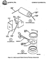
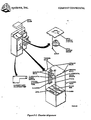
- FIG. 1 there is shown a block diagram of an overall stereolithography system suitable for practicing the present invention.
- a CAD generator 2 and appropriate interface 3 provide a data description of the object to be formed, typically in PHIGS format, via network communication such' as ETHERNET or the like to an interface computer 4 where the object data is manipulated to optimize the data and provide output vectors which reduce stress, curl and distortion, and increase resolution, strength, accuracy, speed and economy of reproduction, even for rather difficult and complex object shapes.
- the interface computer 4 generates layer data by slicing, varying layer thickness, rounding polygon vertices, filling, generating flat skins, near-flat skins, up-facing and down-facing skins, scaling, cross-hatching, offsetting vectors and ordering of vectors. More details about the vector types are available in S.N. 182,830, its CIP, S.N. 269,801 and its continuation, Lyon & Lyon Docket No. 186/195. Briefly, boundary vectors are used to trace the outline of each cross-section, hatch vectors are used to provide internal structure between the boundary vectors, and skin vectors are used to define the outer surfaces of the object. They are traced in the following order: boundary, hatch, skin.
- the vector data and parameters from the computer 4 are directed to a controller subsystem 5 for operating the system stereolithography laser, mirrors, elevator and the like.
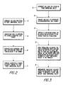
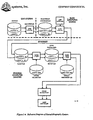
- FIGS. 2 and 3 are flow charts illustrating the basic system of the present invention for generating three-dimensional objects by means of stereolithography.
- UV curable chemicals are known which can be induced to change to solid state polymer plastic by irradiation with ultraviolet light (UV) or other forms of synergistic stimulation such as electron beams, visible or invisible light, reactive chemicals applied by ink jet or via a suitable mask.
- UV curable chemicals are currently used as ink for high speed printing, in processes of coating or paper and other materials, as adhesives, and in other specialty areas.
- Lithography is the art of reproducing graphic objects, using various techniques. Modern examples include photographic reproduction, xerography, and microlithography, as is used in the production of microelectronics. Computer generated graphics displayed on a plotter or a cathode ray tube are also forms of lithography, where the image is a picture of a computer coded object.
- Computer aided design (CAD) and computer aided manufacturing (CAM) are techniques that apply the abilities of computers to the processes of designing and manufacturing.
- a typical example of CAD is in the area of electronic printed circuit design, where a computer and plotter draw the design of a printed circuit board, given the design parameters as computer data input.
- a typical example of CAM is a numerically controlled milling machine, where a computer and a milling machine produce metal parts, given the proper programming instructions. Both CAD and CAM are important and are rapidly growing technologies.
- a prime object of the present invention is to harness the principles of computer generated graphics, combined with UV curable plastic and the like, to simultaneously execute CAD and CAM, and to produce three-dimensional objects directly from computer instructions.
- This invention referred to as stereolithography, can be used to sculpture models and prototypes in a design phase of product development, or as a manufacturing device, or even as an art form.
- the present invention enhances the developments in stereolithography set forth in U.S. Patent No. 4,575,330, issued March 11, 1986, to Charles W. Hull, one of the inventors herein.
- Step 8 calls for generation of CAD or other data, typically in digital form, representing a three-dimensional object to be formed by the system.
- This CAD data usually defines surfaces in polygon format, triangles and normals perpendicular to the planes of those triangles, e.g., for slope indications, being presently preferred, and in a presently preferred embodiment of the invention conforms to the Programmer's Hierarchial Interactive Graphics System (PHIGS) now adapted as an ANSI standard.
- PHIGS Hierarchial Interactive Graphics System
- Step 9 the PHIGS data or its equivalent is converted, in accordance with the invention, by a unique conversion system to a modified data base for driving the stereolithography output system in forming three-dimensional objects.
- information defining the object is specially processed to reduce stress, curl and distortion, and increase resolution, strength and accuracy of reproduction.
- Step 10 in FIG. 2 calls for the generation of individual solid laminae representing cross-sections of a three-dimensional object to be formed.
- Step 11 combines the successively formed adjacent lamine to form the desired three-dimensional object which has been programmed into the system for selective curing.
- the stereolithographic system of the present invention generates three-dimensional objects by creating a cross-sectional pattern of the object to be formed at a selected surface of a fluid medium, e.g., a UV curable liquid or the like, capable of altering its physical state in response to appropriate synergistic stimulation such as impinging radiation, electron beam or other particle bombardment, or applied chemicals (as by ink jet or spraying over a mask adjacent the fluid surface), successive adjacent laminae, representing corresponding successive adjacent cross-sections of the object, being automatically formed and integrated together to provide a step-wise laminar or thin layer buildup of the object, whereby a three-dimensional object is formed and drawn from a substantially planar or sheet-like surface of the fluid medium during the forming process.
- a fluid medium e.g., a UV curable liquid or the like
- Step 8 calls for generation of CAD or other data, typically in digital form, representing a three-dimensional object to be formed by the system.
- the PHIGS data is converted by a unique conversion system to a modified data base for driving the stereolithography output system in forming three-dimensional objects.
- Step 12 calls for containing a fluid medium capable of solidification in response to prescribed reactive stimulation.
- Step 13 calls for application of that stimulation as a graphic pattern, in response to data output from the computer 4 in Fig. 1, at a designated fluid surface to form thin, solid, individual layers at that surface, each layer representing an adjacent cross-section of a three-dimensional object to be produced.
- each lamina will be a thin lamina, but thick enough to be adequately cohesive in forming the cross-section and adhering to the adjacent laminae defining other cross-sections of the object being formed.
- Step 14 in FIG. 3 calls for superimposing successive adjacent layers or laminae on each other as they are formed, to integrate the various layers and define the desired three-dimensional object.
- the fluid medium cures and solid material forms to define one lamina
- that lamina is moved away from the working surface of the fluid medium and the next lamina is formed in the new liquid which replaces the previously formed lamina, so that each successive lamina is superimposed and integral with (by virtue of the natural adhesive properties of the cured fluid medium) all of the other cross-sectional laminae.
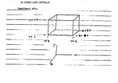
- the present invention also deals with the problems posed in transitioning between vertical and horizontal.
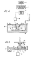
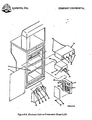
- FIGS. 4-5 of the drawings illustrate various apparatus suitable for implementing the stereolithographic methods illustrated and described by the systems and flow charts of FIGS. 1-3.
- Stepolithography is a method and apparatus for making solid objects by successively “printing” thin layers of a curable material, e.g., a UV curable material, one on top of the other.
- a curable material e.g., a UV curable material
- a programmable movable spot beam of UV light shining on a surface or layer of UV curable liquid is used to form a solid cross-section of the object at the surface of the liquid.
- the object is then moved, in a programmed manner, away from the liquid surface by the thickness of one layer and the next cross-section is then formed and adhered to the immediately preceding layer defining the object. This process is continued until the entire object is formed.
- the data base of a CAD system can take several forms.
- One form as previously indicated, consists of representing the surface of an object as a mesh of triangles (PHIGS). These triangles completely form the inner and outer surfaces of the object.
- This CAD representation also includes a unit length normal vector for each triangle. The normal points away from the solid which the triangle is bounding.
- This invention provides a means of processing such CAD data into the layer-by-layer vector data that is necessary for forming objects through stereolithography.
- plastic from one layer must overlay plastic that was formed when the previous layer was built.
- plastic that is formed on one layer will fall exactly on previously formed plastic from the preceding layer, and thereby provide good adhesion.
- a point will eventually be reached where the plastic formed on one layer does not make contact with the plastic formed on the previous layer, and this causes severe adhesion problems.
- Horizontal surfaces themselves do not present adhesion problems because by being horizontal the whole section is built on one layer with side-to-side adhesion maintaining structural integrity. Therefore, means are provided for insuring adhesion between layers when making transitions from vertical to horizontal or horizontal to vertical sections, as well as providing a way to completely bound a surface, and ways to reduce or eliminate stress and strain in formed parts.
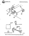
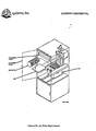
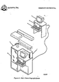
- a presently preferred embodiment of a new and improved stereolithographic system is shown in elevational cross-section in FIG. 4.
- a container 21 is filled with a UV curable liquid 22 or the like, to provide a designated working surface 23.
- a programmable source of ultraviolet light 26 or the like produces a spot of ultraviolet light 27 in the plane of surface 23.
- the spot 27 is movable across the surface 23 by the motion of mirrors or other optical or mechanical elements (not shown in Fig. 4) used with the light source 26.
- the position of the spot 27 on surface 23 is controlled by a computer control system 28.
- the system 28 may be under control of CAD data produced by a generator 20 in a CAD design system or the like and directed in PHIGS format or its equivalent to a computerized conversion system 25 where information defining the object is specially processed to reduce stress, curl and distortion, and increase resolution, strength and accuracy of reproduction.
- a movable elevator platform 29 inside container 21 can be moved up and down selectively, the position of the platform being controlled by the system 28. As the device operates, it produces a three-dimensional object 30 by step-wise buildup of integrated laminae such as 30a, 30b, 30c.
- the surface' of the UV curable liquid 22 is maintained at a constant level in the container 21, and the spot of UV light 27, or other suitable form of reactive stimulation, of sufficient intensity to cure the liquid and convert it to a solid material is moved across the working surface 23 in a programmed manner.
- the elevator platform 29 that was initially just below surface 23 is moved down from the surface in a programmed manner by any suitable actuator. In this way, the solid material that was initially formed is taken below surface 23 and new liquid 22 flows across the surface 23. A portion of this new liquid is, in turn, converted to solid material by the programmed UV light spot 27, and the new material adhesively connects to the material below it. This process is continued until the entire three-dimensional object 30 is formed.
- the object 30 is then removed from the container 21, and the apparatus is ready to produce another object. Another object can then be produced, or some new object can be made by changing the program irr the computer 28.
- the curable liquid 22, e.g., UV curable liquid, must have several important properties.
- E It must be reasonably insoluble in that same solvent in the solid state, so that the object can be washed free of the UV cure liquid and partially cured liquid after the object has been formed.
- the cured material must also have desirable properties once it is in the solid state. These properties depend on the application involved, as in the conventional use of other plastic materials. Such parameters as color, texture, strength, electrical properties, flammability, and flexibility are among the properties to be considered. In addition, the cost of the material will be important in many cases.
- the UV curable material used in the presently preferred embodiment of a working stereolithograph is DeSoto SLR 800 stereolithography resin, made by DeSoto, Inc. of Des Plains, Illinois.
- the light source 26 produces the spot 27 of UV light small enough to allow the desired object detail to be formed, and intense enough to cure the UV curable liquid being used quickly enough to be practical.
- the source 26 is arranged so it can be programmed to be turned off and on, and to move, such that the focused spot 27 moves across the surface 23 of the liquid 22.
- the spot 27 moves, it cures the liquid 22 into a solid, and "draws" a solid pattern on the surface in much the same way a chart recorder or plotter uses a pen to draw a pattern on paper.
- the light source 26 for the presently preferred embodiment of a stereolithography is typically a helium-cadmium ultraviolet laser such as the Model 4240-N HeCd Multimode Laser, made by Liconix of Sunnyvale, California.
- means may be provided to keep the surface 23 at a constant level and to replenish this material after an object has been removed, so that the focus spot 27 will remain sharply in focus on a fixed focus plane, thus insuring maximum resolution in forming a high layer along the working surface.
- the elevator platform 29 is used to support and hold the object 30 being formed, and to move it up and down as required. Typically, after a layer is formed, the object 30 is moved beyond the level of the next layer to allow the liquid 22 to flow into the momentary void at surface 23 left where the solid was formed, and then it is moved back to the correct level for the next layer.
- the requirements for the elevator platform 29 are that it can be moved in a programmed fashion at appropriate speeds, with adequate precision, and that it is powerful enough to handle the weight of the object 30 being formed. In addition, a manual fine adjustment of the elevator platform position is useful during the set-up phase and when the object is being removed.
- the elevator platform 29 can be mechanical, pneumatic, hydraulic, or electrical and may also be optical or electronic feedback to precisely control its position.
- the elevator platform 29 is typically fabricated of either glass or aluminum, but any material to which the cured plastic material will adhere is suitable.
- a computer controlled pump may be used to maintain a constant level of the liquid 22 at the working surface 23.
- Appropriate level detection system and feedback networks can be used to drive a fluid pump or a liquid displacement device, such as a solid rod (not shown) which is moved out of the fluid medium as the elevator platform is moved further into the fluid medium, to offset changes in fluid volume and maintain constant fluid level at the surface 23.
- the source 26 can be moved relative to the sensed level 23 and automatically maintain sharp focus at the working surface 23. All of these alternatives can be readily achieved by appropriate data operating in conjunction with the computer control system 28.
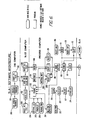
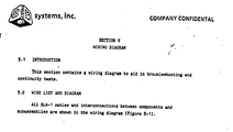
- Fig. 6 of the drawings illustrates the overall software architecture of a stereolithography system in which the present invention may be practiced.
- SLICE portion of our processing referred to as "SLICE” takes in the object that you want to build, together with any scaffolding or supports that are necessary to make it more buildable. These supports are typically generated by the user's CAD. The first thing SLICE does is to find the outlines of the object and its supports.
- SLICE defines each microsection or layer one at a time under certain specified controlling styles. SLICE produces a boundary to the solid portion of the object. If, for instance, the object is hollow, there will be an outside surface and an inside one. This outline then is the primary information. The SLICE program then takes that outline or series of outlines and says, but if you build an outside skin and an inside skin they won't join to one another, you'll have liquid between them. It will collapse.
- a third group consists of skins and there are subgroups of those, upward facing skins, downward facing skins which have to be treated slightly differently. These subgroups are all tracked differently because they may get slightly different treatment, in the process the output data is then appropriately managed to form the desired object and supports. More detail about the different vector types produced by SLICE are contained in S.N. 182,830, its CTP, S.N. 269,801, and its continuation Lyon & Lyon Docket No. 186/195.
- the elevator platform 29 is raised and the object is removed from the platform for post processing.
- each container 21 having a different type of curable material that can ' be. automatically selected by the stereolithographic system.
- the various materials might provide plastics of different colors, or have both insulating and conducting material available for the various layers of electronic products.
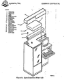
- FIG. 5 of the drawings there is shown an alternate configuration of a stereolithograph wherein the UV curable liquid 22 or the like floats on a heavier UV transparent liquid 32 which is non-miscible and non-wetting with the curable liquid 22.
- ethylene glycol or heavy water are suitable for the intermediate liquid layer 32.
- the three-dimensional object 30 is pulled up from the liquid 22, rather than down and further into the liquid medium, as shown in the system of FIG. 3.
- the UV light source 26 in FIG. 5 focuses the spot 27 at the interface between the liquid 22 and the non-miscible intermediate liquid layer 32, the UV radiation passing through a suitable UV transparent window 33, of quartz or the like, supported at the bottom of the container 21.
- the curable liquid 22 is provided in a very thin layer over the non-miscible layer 32 and thereby has the advantage of limiting layer thickness directly rather than relying solely upon adsorption and the like to limit the depth of curing since ideally an ultra-thin lamina is to be provided. Hence, the region of formation will be more sharply defined and some surfaces will be formed smoother with the system of FIG. 5 than with that of FIG. 4. In addition a smaller volume of UV curable liquid 22 is required, and the substitution of one curable material for another is easier.
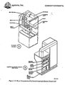
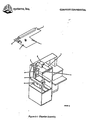
- a commercial stereolithography system will have additional components and subsystems besides those previously shown in connection with the schematically depicted systems of FIGS. 1-5.
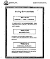
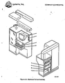
- the commercial system would also have a frame and housing, and a control panel. It should have means to shield the operator from excess UV and visible light, and it may also have means to allow viewing of the object 30 while it is being formed.
- Commercial units will provide safety means for controlling ozone and noxious fumes, as well as conventional high voltage safety protection and interlocks. Such commercial units will also have means to effectively shield the sensitive electronics from electronic noise sources.
- the present invention addresses some additional problems encountered in the practice of stereolithography.
- Each new layer of a stereolithographic part tends to pull upward on the next lower layer while it is being formed. This is a direct result of stresses created by the curing layer as the liquid is converted to solid. This action may cause both layers to curl upward, dependent on the geometry of the layers and whether or not the lower layer is securely held in place either by supports or by strong adhesion to the next lower layer.
- Certain of these shapes are more susceptible to curling, and may require special design features known as Smalleys in order to inhibit or minimize curl.
- the liquid plastic used in stereolithography is less dense than as a solid. This means that the solid will take up less volume and will tend to pull on the lower layer as it shrinks.
- the plastic expands when it is heated by the polymerization process and subsequently contracts as it cools. Since the new layer formed by the laser is firmly bonded to the lower layer, it tends to pull upward on the lower layer as it cools.
- the second method is to isolate sections of a part so that the stresses cannot propagate over large distances and will not be transmitted beyond certain stress points in the part.
- Layer sections prone to curling may be isolated by designing small holes or gaps at stress points in the CAD design of the part. These gaps, called “Smalleys", block propagation of stresses along layer sections. This reduces the stresses acting on a part to only those created within the section. If the Smalleys are properly designed, these localized stresses will be below the threshold value which would curl the layer section.
- Smalleys inhibit the transmission of stress from one section to another. They also serve to limit the stress to an amount that will minimize distortion in a given section (by limiting the stress before it gets large enough to cause distortion).
- Smalleys are generally designed on the CAD to be 15 to 30 mils wide (depending on the expected cure width). They are also generally designed 40 to 80 mils tall (depending on the strength of the material and part geometry). When the material is cured, the Smalleys narrow by a full cure width of material. Hence, the right choice of design width can yield Smalleys that are almost completely hidden after post curing. It must be noted, however, that Smalleys must be designed so that when boundary vectors are drawn the Smalleys do not completely close. This is typically accomplished during the CAD design of the object. When we implement the ability to offset vectors to account for finite cure width of material, the width of design of Smalleys can be reduced to a few mils.
- Beam width compensation moves the border vectors for a cross section inwards by one half the beam width, so that cross section, once cured, will more accurately represent the object.
- a floating or unsupported line of plastic does not distort from its drawn shape. It distorts only when another curing line of plastic comes into contact with it.
- This second line of plastic shrinks as it is drawn, so if it contacts the first (previously cured) line, the first line will be bent towards the second. If we consider the first line to be constrained in some manner, the distortion caused by the second line will be affected by the constraints to the extent that distortion will only occur in the areas of least resistance. If small gaps are made in this second line, then any stress that develops from the contact with the first line will be isolated between the gaps. If the gaps are used to separate regions of strong structural strength from weaker regions, the stresses from the strong regions cannot propagate to the weaker ones and cause distortion there. Distortion at any point will be less because the stress at that point is less.
- Smalleys are used to isolate regions from stress until they build up enough structural integrity to withstand the stress induced by curing successive layers. This will generally require that the Smalleys be several layers in height. After sufficient strength is developed, the Smalleys can be removed.
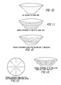
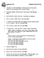
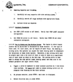
- Example A The continuous layer borders (LBs) of the cylindrical part shown in Figure 7 generate relatively large stresses. These stresses may cause curling if the layers are not adequately adhered to one another.
- Smalleys should be placed at 90 degree intervals around the circumference of the part, with each Smalley typically being 4 to 5 slice layers tall. Each successive set of Smalleys should be offset about 45 degrees to maintain the structural integrity of the part.
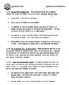
- Example B The unsupported upper edges of the curved windows shown in Figure 8 are highly susceptible to curling. Design Smalleys at the ends of the windows, as shown, but leave one continuous LB under each Smalley.
- Example C The thick interior structure of the part shown in Figure 9 will tend to curl the exterior flanges and other unsupported surfaces. A large Smalley, one that hollows out the interior of the part, as shown, will minimize these stresses.
- Smalleys are typically designed on the CAD to be 15 to 30 mils wide and 40 to 80 mils tall. They generally decrease in size as the part is formed due to the viscous liquid "filling the small gaps during dipping. Thus, if designed properly, Smalleys will prevent curl and then effectively disappear or reduce in size to narrow slits or slight indentations on the surface of the part during post curing.
- Smalleys are also used to reduce birdnesting.
- the width of Smalleys, for this application, is generally less than cure width, so that after curing they are completely filled in and so no structural integrity is lost through their use.
- Smalleys are placed periodically in regions of down-facing, near-flat triangles with heights appropriate to extend vertically through the near-flat triangles. The placement of Smalleys is based on several factors that affect the likelihood of having birdnesting problems.
- the radius of curvature of the boundaries, the length of near-flat zones, the likelihood of boundaries moving, etc. are significant. Smalleys do not need to penetrate completely through a wall, as they do in their other application, but they do need to penetrate deep enough to insure a contact point with the boundaries on the previous layer.
- Birdnesting can occur in objects that do not have near-flat triangles, but only when there are adhesion problems between layers (for example, when an object is built using dip delays that are too short). Smalleys can be used in these situations to help eliminate birdnesting also.
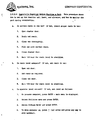
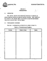
- FIG. 10 is a side view of a CAD designed cone without Smalleys.
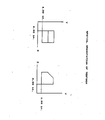
- FIGS. 11 and 12 are views of the sliced CAD designed cone and what it might look like after building.
- FIG. 13 is a top view of a CAD designed cone showing possible locations in the XY plane where Smalleys might be inserted.
- FIG. 14 is a side view of a sliced CAD designed cone with Smalleys and what it might look like after building.
- Boundary vectors can move out of position for a couple of reasons: 1) convection currents within the liquid that can cause floating items to drift, 2) distortions of boundary vectors from making contact with already cured (but floating material), 3) newly cured material contacting, and distorting, boundary vectors before they are secured into position, and 4) shrinking of hatch as it starts to secure one side of the boundary causing the boundary to be pulled out of position.
- a couple of these causes can affect boundary vectors that are not associated with near-flat triangles, so if problems are found in non-near-flat regions, Smalleys may be useful.
- Boundaries can only birdnest when they can move or sections of them can move far enough out of position so that when cross-hatching is drawn, it does not contact the boundaries. Smalleys avoid this problem by having the boundaries cut in over the top of the boundaries from the previous layer, on a periodic basis. This cutting in over the top of previously cured boundaries prevents the present boundaries from moving out of position.
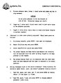
- FIG. 15 is a top view of two cross-sections of a cone with no Smalleys.
- FIG. 16 is a top view of two cross-sections of a cone with the second layer only showing the boundary vectors drawn.
- FIG. 17 is a top view of two cross-sections of a cone with the second layer showing the boundary vectors not making contact with cross-hatch in a particular location.
- FIG. 18 is a top view of two cross-sections of a cone with Smalleys.
- FIG. 19 is a top view of two cross-sections of a cone with Smalleys with the second layer only showing the boundary vectors drawn.
- FIG. 20 is a top view of two cross-sections of a cone with Smalleys with the second layer showing the boundary vectors making contact with cross-hatch everywhere.
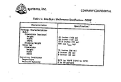
- Appendix A is a 3D Systems, Inc.
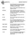
- Beta Site Users Manual and Systems Manual describing the overall system for an early Model SLA-1 Stereolithography System, including installation and operation
- Appendix I is a 3D Systems, Inc.
- Stereolithography CAD/CAM Interface Specification is illustrated and described by the enclosed appendices, wherein Appendix A is a 3D Systems, Inc. Beta Site Users Manual and Systems Manual describing the overall system for an early Model SLA-1 Stereolithography System, including installation and operation, and Appendix I is a 3D Systems, Inc. Stereolithography CAD/CAM Interface Specification.
- the new and improved stereolithographic method and apparatus has many advantages over currently used methods for producing plastic objects.
- the method avoids the need of producing tooling drawings and tooling.
- the designer can work directly with the computer and a stereolithographic device, and when he is satisfied with the design as displayed on the output screen of the computer, he can fabricate a part for direct examination, information defining the object being specially processed to reduce curl, stress, birdnesting and other distortions, and increase resolution, strength and accuracy of reproduction. If the design has to be modified, it can be easily done through the computer, and then another part can be made to verify that the change was correct. If the design calls for several parts with interacting design parameters, the method becomes even more useful because all of the part designs can be quickly changed and made again so that the total assembly can be made and examined, repeatedly if necessary.
- part production can begin immediately, so that the weeks and months between design and production are avoided. Ultimate production rates and parts costs should be similar to current injection molding costs for short run production, with even lower labor costs than those associated with injection molding. Injection molding is economical only when large numbers of identical parts are required. Stereolithography is particularly useful for short run production because the need for tooling is eliminated and production set-up time is minimal. Likewise, design changes and custom parts are easily provided using the technique. Because of the ease of making parts, stereolithography can allow plastic parts to be used in many places where metal or other material parts are now used. Moreover, it allows plastic models of objects to be quickly and economically provided, prior to the decision to make more expensive metal or other material parts.
- the present invention satisfies a long existing need in the art for a CAD and CAM system capable of rapidly, reliably, accurately and economically designing and fabricating three-dimensional plastic parts and the like.
Landscapes
- Engineering & Computer Science (AREA)
- Materials Engineering (AREA)
- Chemical & Material Sciences (AREA)
- Optics & Photonics (AREA)
- Physics & Mathematics (AREA)
- Manufacturing & Machinery (AREA)
- Mechanical Engineering (AREA)
- Crystals, And After-Treatments Of Crystals (AREA)
- Preparing Plates And Mask In Photomechanical Process (AREA)
- Heating, Cooling, Or Curing Plastics Or The Like In General (AREA)
- Treatments Of Macromolecular Shaped Articles (AREA)
- Prostheses (AREA)
- Electron Beam Exposure (AREA)
- Axle Suspensions And Sidecars For Cycles (AREA)
- Transition And Organic Metals Composition Catalysts For Addition Polymerization (AREA)
Applications Claiming Priority (2)
| Application Number | Priority Date | Filing Date | Title |
|---|---|---|---|
| US183015 | 1988-04-18 | ||
| US07/183,015 US5015424A (en) | 1988-04-18 | 1988-04-18 | Methods and apparatus for production of three-dimensional objects by stereolithography |
Publications (3)
| Publication Number | Publication Date |
|---|---|
| EP0355945A2 true EP0355945A2 (de) | 1990-02-28 |
| EP0355945A3 EP0355945A3 (de) | 1991-10-09 |
| EP0355945B1 EP0355945B1 (de) | 1997-06-18 |
Family
ID=22671066
Family Applications (1)
| Application Number | Title | Priority Date | Filing Date |
|---|---|---|---|
| EP89303785A Expired - Lifetime EP0355945B1 (de) | 1988-04-18 | 1989-04-17 | Verringerung der Verformung von stereolithografischen Teilen durch Isolierung der Spannungen |
Country Status (10)
| Country | Link |
|---|---|
| US (1) | US5015424A (de) |
| EP (1) | EP0355945B1 (de) |
| JP (1) | JP3030853B2 (de) |
| KR (1) | KR900700274A (de) |
| AT (1) | ATE154541T1 (de) |
| CA (1) | CA1338628C (de) |
| DE (2) | DE68928133T2 (de) |
| HK (1) | HK1001677A1 (de) |
| IL (1) | IL89979A0 (de) |
| WO (1) | WO1989010255A1 (de) |
Families Citing this family (70)
| Publication number | Priority date | Publication date | Assignee | Title |
|---|---|---|---|---|
| US5772947A (en) * | 1988-04-18 | 1998-06-30 | 3D Systems Inc | Stereolithographic curl reduction |
| WO1989010801A1 (en) * | 1988-04-18 | 1989-11-16 | 3D Systems, Inc. | Stereolithographic curl reduction |
| US5965079A (en) | 1995-04-25 | 1999-10-12 | 3D Systems, Inc. | Method and apparatus for making a three-dimensional object by stereolithography |
| US5354695A (en) | 1992-04-08 | 1994-10-11 | Leedy Glenn J | Membrane dielectric isolation IC fabrication |
| JP2715527B2 (ja) * | 1989-03-14 | 1998-02-18 | ソニー株式会社 | 立体形状形成方法 |
| US5014207A (en) * | 1989-04-21 | 1991-05-07 | E. I. Du Pont De Nemours And Company | Solid imaging system |
| JPH0336019A (ja) * | 1989-07-03 | 1991-02-15 | Brother Ind Ltd | 三次元成形方法およびその装置 |
| US5133987A (en) * | 1989-10-27 | 1992-07-28 | 3D Systems, Inc. | Stereolithographic apparatus and method |
| US5999184A (en) | 1990-10-30 | 1999-12-07 | 3D Systems, Inc. | Simultaneous multiple layer curing in stereolithography |
| US5474719A (en) * | 1991-02-14 | 1995-12-12 | E. I. Du Pont De Nemours And Company | Method for forming solid objects utilizing viscosity reducible compositions |
| US6714625B1 (en) | 1992-04-08 | 2004-03-30 | Elm Technology Corporation | Lithography device for semiconductor circuit pattern generation |
| US5545367A (en) * | 1992-04-15 | 1996-08-13 | Soane Technologies, Inc. | Rapid prototype three dimensional stereolithography |
| US5296335A (en) * | 1993-02-22 | 1994-03-22 | E-Systems, Inc. | Method for manufacturing fiber-reinforced parts utilizing stereolithography tooling |
| DE4309524C2 (de) * | 1993-03-24 | 1998-05-20 | Eos Electro Optical Syst | Verfahren zum Herstellen eines dreidimensionalen Objekts |
| KR970011573B1 (ko) * | 1993-04-14 | 1997-07-12 | 마쯔시다덴기산교 가부시기가이샤 | 3차원 조형방법 |
| BE1008128A3 (nl) * | 1994-03-10 | 1996-01-23 | Materialise Nv | Werkwijze voor het ondersteunen van een voorwerp vervaardigd door stereolithografie of een andere snelle prototypevervaardigingswerkwijze en voor het vervaardigen van de daarbij gebruikte steunkonstruktie. |
| US5590454A (en) * | 1994-12-21 | 1997-01-07 | Richardson; Kendrick E. | Method and apparatus for producing parts by layered subtractive machine tool techniques |
| US5573721A (en) * | 1995-02-16 | 1996-11-12 | Hercules Incorporated | Use of a support liquid to manufacture three-dimensional objects |
| US5669433A (en) * | 1995-09-08 | 1997-09-23 | Aeroquip Corporation | Method for creating a free-form metal three-dimensional article using a layer-by-layer deposition of a molten metal |
| US5617911A (en) * | 1995-09-08 | 1997-04-08 | Aeroquip Corporation | Method and apparatus for creating a free-form three-dimensional article using a layer-by-layer deposition of a support material and a deposition material |
| US5718951A (en) * | 1995-09-08 | 1998-02-17 | Aeroquip Corporation | Method and apparatus for creating a free-form three-dimensional article using a layer-by-layer deposition of a molten metal and deposition of a powdered metal as a support material |
| US5787965A (en) * | 1995-09-08 | 1998-08-04 | Aeroquip Corporation | Apparatus for creating a free-form metal three-dimensional article using a layer-by-layer deposition of a molten metal in an evacuation chamber with inert environment |
| US5746844A (en) * | 1995-09-08 | 1998-05-05 | Aeroquip Corporation | Method and apparatus for creating a free-form three-dimensional article using a layer-by-layer deposition of molten metal and using a stress-reducing annealing process on the deposited metal |
| US6270335B2 (en) * | 1995-09-27 | 2001-08-07 | 3D Systems, Inc. | Selective deposition modeling method and apparatus for forming three-dimensional objects and supports |
| US7332537B2 (en) | 1996-09-04 | 2008-02-19 | Z Corporation | Three dimensional printing material system and method |
| US6051179A (en) * | 1997-03-19 | 2000-04-18 | Replicator Systems, Inc. | Apparatus and method for production of three-dimensional models by spatial light modulator |
| US6551857B2 (en) | 1997-04-04 | 2003-04-22 | Elm Technology Corporation | Three dimensional structure integrated circuits |
| US6084980A (en) * | 1997-05-13 | 2000-07-04 | 3D Systems, Inc. | Method of and apparatus for deriving data intermediate to cross-sectional data descriptive of a three-dimensional object |
| US6696221B1 (en) | 1997-05-19 | 2004-02-24 | Day International, Inc. | Printing plate and method of making using digital imaging photopolymerization |
| US6207097B1 (en) | 1998-02-18 | 2001-03-27 | Norma Jean Iverson | Method for manufacturing physical objects using precision stereolithography |
| US6932145B2 (en) * | 1998-11-20 | 2005-08-23 | Rolls-Royce Corporation | Method and apparatus for production of a cast component |
| US7343960B1 (en) | 1998-11-20 | 2008-03-18 | Rolls-Royce Corporation | Method and apparatus for production of a cast component |
| US6524346B1 (en) * | 1999-02-26 | 2003-02-25 | Micron Technology, Inc. | Stereolithographic method for applying materials to electronic component substrates and resulting structures |
| US6391245B1 (en) | 1999-04-13 | 2002-05-21 | Eom Technologies, L.L.C. | Method for creating three-dimensional objects by cross-sectional lithography |
| WO2001034371A2 (en) | 1999-11-05 | 2001-05-17 | Z Corporation | Material systems and methods of three-dimensional printing |
| US6712856B1 (en) * | 2000-03-17 | 2004-03-30 | Kinamed, Inc. | Custom replacement device for resurfacing a femur and method of making the same |
| US20010050031A1 (en) | 2000-04-14 | 2001-12-13 | Z Corporation | Compositions for three-dimensional printing of solid objects |
| US6500378B1 (en) | 2000-07-13 | 2002-12-31 | Eom Technologies, L.L.C. | Method and apparatus for creating three-dimensional objects by cross-sectional lithography |
| BE1013641A3 (nl) * | 2000-08-09 | 2002-05-07 | Materialise Nv | Werkwijze voor het vervaardigen van een steun-en/of referentieconstructie. |
| US6607689B1 (en) * | 2000-08-29 | 2003-08-19 | Micron Technology, Inc. | Layer thickness control for stereolithography utilizing variable liquid elevation and laser focal length |
| JP2006500117A (ja) | 2002-09-23 | 2006-01-05 | ヴォルケイノウ・コーポレーション | クロストークを低減する配線構造を有するセンサ・カテーテル |
| US8086336B2 (en) * | 2002-09-30 | 2011-12-27 | Medical Modeling Inc. | Method for design and production of a custom-fit prosthesis |
| US7098463B2 (en) * | 2003-03-03 | 2006-08-29 | Heuris Pharma, Llc | Three-dimensional dosimeter for penetrating radiation and method of use |
| CA2526100A1 (en) | 2003-05-21 | 2004-12-29 | Z Corporation | Thermoplastic powder material system for appearance models from 3d printing systems |
| US20040254665A1 (en) * | 2003-06-10 | 2004-12-16 | Fink Jeffrey E. | Optimal dimensional and mechanical properties of laser sintered hardware by thermal analysis and parameter optimization |
| US20100174392A1 (en) * | 2003-06-10 | 2010-07-08 | Fink Jeffrey E | Optimal dimensional and mechanical properties of laser sintered hardware by thermal analysis and parameter optimization |
| US20070020793A1 (en) * | 2004-03-01 | 2007-01-25 | Adamovics John A | Three-dimensional shaped solid dosimeter and method of use |
| US7261542B2 (en) | 2004-03-18 | 2007-08-28 | Desktop Factory, Inc. | Apparatus for three dimensional printing using image layers |
| US7547978B2 (en) * | 2004-06-14 | 2009-06-16 | Micron Technology, Inc. | Underfill and encapsulation of semiconductor assemblies with materials having differing properties |
| US7235431B2 (en) * | 2004-09-02 | 2007-06-26 | Micron Technology, Inc. | Methods for packaging a plurality of semiconductor dice using a flowable dielectric material |
| CN101568422B (zh) | 2006-12-08 | 2013-02-13 | 3D系统公司 | 使用过氧化物固化的三维印刷材料体系和方法 |
| WO2008086033A1 (en) | 2007-01-10 | 2008-07-17 | Z Corporation | Three-dimensional printing material system with improved color, article performance, and ease of use |
| US7968626B2 (en) | 2007-02-22 | 2011-06-28 | Z Corporation | Three dimensional printing material system and method using plasticizer-assisted sintering |
| US7963020B2 (en) * | 2007-08-28 | 2011-06-21 | Sealed Air Corporation (Us) | Apparatus and method for manufacturing foam parts |
| US7923298B2 (en) | 2007-09-07 | 2011-04-12 | Micron Technology, Inc. | Imager die package and methods of packaging an imager die on a temporary carrier |
| WO2010074566A1 (en) | 2008-12-22 | 2010-07-01 | Nederlandse Organisatie Voor Toegepast-Natuurwetenschappelijk Onderzoek Tno | Method and apparatus for layerwise production of a 3d object |
| US8678805B2 (en) | 2008-12-22 | 2014-03-25 | Dsm Ip Assets Bv | System and method for layerwise production of a tangible object |
| US8777602B2 (en) | 2008-12-22 | 2014-07-15 | Nederlandse Organisatie Voor Tobgepast-Natuurwetenschappelijk Onderzoek TNO | Method and apparatus for layerwise production of a 3D object |
| US8460451B2 (en) | 2011-02-23 | 2013-06-11 | 3D Systems, Inc. | Support material and applications thereof |
| US9394441B2 (en) | 2011-03-09 | 2016-07-19 | 3D Systems, Inc. | Build material and applications thereof |
| US9157007B2 (en) | 2011-03-09 | 2015-10-13 | 3D Systems, Incorporated | Build material and applications thereof |
| KR101450749B1 (ko) * | 2013-10-29 | 2014-10-17 | 서강대학교산학협력단 | 미소 캔틸레버 제조방법 |
| MX2016010901A (es) * | 2014-02-28 | 2016-11-18 | Maurizio Costabeber Ettore | Maquina de estereolitografia mejorada. |
| US9844917B2 (en) | 2014-06-13 | 2017-12-19 | Siemens Product Lifestyle Management Inc. | Support structures for additive manufacturing of solid models |
| KR101619696B1 (ko) * | 2015-03-16 | 2016-05-10 | 엘지전자 주식회사 | 3d 프린터 |
| US20170291261A1 (en) * | 2015-06-12 | 2017-10-12 | Ashok Chand Mathur | Method And Apparatus Of Very Much Faster 3D Printer |
| EP3515709B1 (de) | 2016-09-26 | 2022-11-30 | Formlabs, Inc. | Verfahren zur konfigurierung einer additiven herstellungsvorrichtung zur herstellung eines objekts |
| US11639030B2 (en) * | 2017-02-03 | 2023-05-02 | Mimaki Engineering Co., Ltd. | Manufacturing method and shaping device for shaped object |
| KR102780988B1 (ko) | 2020-02-04 | 2025-03-17 | 캐보트 코포레이션 | 액체-기반 적층 제조를 위한 조성물 |
| US11945155B2 (en) | 2020-09-21 | 2024-04-02 | Formlabs, Inc. | Techniques for reducing peel forces in additive fabrication and related systems and methods |
Family Cites Families (5)
| Publication number | Priority date | Publication date | Assignee | Title |
|---|---|---|---|---|
| US2775758A (en) * | 1951-05-25 | 1956-12-25 | Munz Otto John | Photo-glyph recording |
| US4575330A (en) * | 1984-08-08 | 1986-03-11 | Uvp, Inc. | Apparatus for production of three-dimensional objects by stereolithography |
| EP0250121B1 (de) * | 1986-06-03 | 1994-11-02 | Cubital Ltd. | Gerät zur Entwicklung dreidimensionaler Modelle |
| US4801477A (en) * | 1987-09-29 | 1989-01-31 | Fudim Efrem V | Method and apparatus for production of three-dimensional objects by photosolidification |
| US4752498A (en) * | 1987-03-02 | 1988-06-21 | Fudim Efrem V | Method and apparatus for production of three-dimensional objects by photosolidification |
-
1988
- 1988-04-18 US US07/183,015 patent/US5015424A/en not_active Expired - Fee Related
-
1989
- 1989-04-17 CA CA000596850A patent/CA1338628C/en not_active Expired - Fee Related
- 1989-04-17 DE DE68928133T patent/DE68928133T2/de not_active Expired - Fee Related
- 1989-04-17 KR KR1019890702386A patent/KR900700274A/ko not_active Withdrawn
- 1989-04-17 WO PCT/US1989/001560 patent/WO1989010255A1/en not_active Ceased
- 1989-04-17 EP EP89303785A patent/EP0355945B1/de not_active Expired - Lifetime
- 1989-04-17 DE DE0355945T patent/DE355945T1/de active Pending
- 1989-04-17 IL IL89979A patent/IL89979A0/xx not_active IP Right Cessation
- 1989-04-17 AT AT89303785T patent/ATE154541T1/de not_active IP Right Cessation
- 1989-04-17 JP JP1504798A patent/JP3030853B2/ja not_active Expired - Lifetime
-
1998
- 1998-01-23 HK HK98100632A patent/HK1001677A1/en not_active IP Right Cessation
Also Published As
| Publication number | Publication date |
|---|---|
| CA1338628C (en) | 1996-10-01 |
| DE68928133D1 (de) | 1997-07-24 |
| EP0355945A3 (de) | 1991-10-09 |
| ATE154541T1 (de) | 1997-07-15 |
| US5015424A (en) | 1991-05-14 |
| DE355945T1 (de) | 1996-06-27 |
| EP0355945B1 (de) | 1997-06-18 |
| KR900700274A (ko) | 1990-08-13 |
| WO1989010255A1 (en) | 1989-11-02 |
| HK1001677A1 (en) | 1998-07-03 |
| IL89979A0 (en) | 1989-12-15 |
| DE68928133T2 (de) | 1997-12-11 |
| JPH04505729A (ja) | 1992-10-08 |
| JP3030853B2 (ja) | 2000-04-10 |
Similar Documents
| Publication | Publication Date | Title |
|---|---|---|
| EP0355945B1 (de) | Verringerung der Verformung von stereolithografischen Teilen durch Isolierung der Spannungen | |
| EP0338751B1 (de) | Träger für Stereolithographie | |
| US4999143A (en) | Methods and apparatus for production of three-dimensional objects by stereolithography | |
| HK1001677B (en) | Reduced stereolithographic part distortion through isolation | |
| US4996010A (en) | Methods and apparatus for production of three-dimensional objects by stereolithography | |
| HK1001674B (en) | Stereolithographic supports | |
| US5571471A (en) | Method of production of three-dimensional objects by stereolithography | |
| US5236637A (en) | Method of and apparatus for production of three dimensional objects by stereolithography | |
| US5344298A (en) | Apparatus for making three-dimensional objects by stereolithography | |
| US5174943A (en) | Method for production of three-dimensional objects by stereolithography | |
| EP0171069B1 (de) | Stereolithographische Vorrichtung und Verfahren zur Herstellung von dreidimensionalen Gegenständen | |
| US4929402A (en) | Method for production of three-dimensional objects by stereolithography | |
| US5076974A (en) | Methods of curing partially polymerized parts | |
| US5772947A (en) | Stereolithographic curl reduction | |
| US5273691A (en) | Stereolithographic curl reduction | |
| US5104592A (en) | Method of and apparatus for production of three-dimensional objects by stereolithography with reduced curl | |
| US5059359A (en) | Methods and apparatus for production of three-dimensional objects by stereolithography | |
| US5164128A (en) | Methods for curing partially polymerized parts | |
| HK1001701B (en) | Method and apparatus for production of three-dimensional objects by stereolithography | |
| CA1339751C (en) | Stereolithographic supports | |
| HK1006793B (en) | Stereolithographic supports | |
| HK1006347B (en) | Method and apparatus for production of three-dimensional objects by stereolithography |
Legal Events
| Date | Code | Title | Description |
|---|---|---|---|
| PUAI | Public reference made under article 153(3) epc to a published international application that has entered the european phase |
Free format text: ORIGINAL CODE: 0009012 |
|
| AK | Designated contracting states |
Kind code of ref document: A2 Designated state(s): AT BE CH DE ES FR GB GR IT LI LU NL SE |
|
| PUAL | Search report despatched |
Free format text: ORIGINAL CODE: 0009013 |
|
| AK | Designated contracting states |
Kind code of ref document: A3 Designated state(s): AT BE CH DE ES FR GB GR IT LI LU NL SE |
|
| 17P | Request for examination filed |
Effective date: 19920324 |
|
| 17Q | First examination report despatched |
Effective date: 19930806 |
|
| GRAG | Despatch of communication of intention to grant |
Free format text: ORIGINAL CODE: EPIDOS AGRA |
|
| DET | De: translation of patent claims | ||
| GRAH | Despatch of communication of intention to grant a patent |
Free format text: ORIGINAL CODE: EPIDOS IGRA |
|
| GRAH | Despatch of communication of intention to grant a patent |
Free format text: ORIGINAL CODE: EPIDOS IGRA |
|
| GRAA | (expected) grant |
Free format text: ORIGINAL CODE: 0009210 |
|
| AK | Designated contracting states |
Kind code of ref document: B1 Designated state(s): AT BE CH DE ES FR GB GR IT LI LU NL SE |
|
| PG25 | Lapsed in a contracting state [announced via postgrant information from national office to epo] |
Ref country code: IT Free format text: LAPSE BECAUSE OF FAILURE TO SUBMIT A TRANSLATION OF THE DESCRIPTION OR TO PAY THE FEE WITHIN THE PRESCRIBED TIME-LIMIT;WARNING: LAPSES OF ITALIAN PATENTS WITH EFFECTIVE DATE BEFORE 2007 MAY HAVE OCCURRED AT ANY TIME BEFORE 2007. THE CORRECT EFFECTIVE DATE MAY BE DIFFERENT FROM THE ONE RECORDED. Effective date: 19970618 Ref country code: NL Free format text: LAPSE BECAUSE OF FAILURE TO SUBMIT A TRANSLATION OF THE DESCRIPTION OR TO PAY THE FEE WITHIN THE PRESCRIBED TIME-LIMIT Effective date: 19970618 Ref country code: LI Free format text: LAPSE BECAUSE OF FAILURE TO SUBMIT A TRANSLATION OF THE DESCRIPTION OR TO PAY THE FEE WITHIN THE PRESCRIBED TIME-LIMIT Effective date: 19970618 Ref country code: AT Effective date: 19970618 Ref country code: ES Free format text: THE PATENT HAS BEEN ANNULLED BY A DECISION OF A NATIONAL AUTHORITY Effective date: 19970618 Ref country code: BE Effective date: 19970618 Ref country code: CH Free format text: LAPSE BECAUSE OF FAILURE TO SUBMIT A TRANSLATION OF THE DESCRIPTION OR TO PAY THE FEE WITHIN THE PRESCRIBED TIME-LIMIT Effective date: 19970618 Ref country code: GR Free format text: LAPSE BECAUSE OF FAILURE TO SUBMIT A TRANSLATION OF THE DESCRIPTION OR TO PAY THE FEE WITHIN THE PRESCRIBED TIME-LIMIT Effective date: 19970618 |
|
| REF | Corresponds to: |
Ref document number: 154541 Country of ref document: AT Date of ref document: 19970715 Kind code of ref document: T |
|
| REG | Reference to a national code |
Ref country code: CH Ref legal event code: EP |
|
| REF | Corresponds to: |
Ref document number: 68928133 Country of ref document: DE Date of ref document: 19970724 |
|
| PG25 | Lapsed in a contracting state [announced via postgrant information from national office to epo] |
Ref country code: SE Effective date: 19970918 |
|
| ET | Fr: translation filed | ||
| NLV1 | Nl: lapsed or annulled due to failure to fulfill the requirements of art. 29p and 29m of the patents act | ||
| REG | Reference to a national code |
Ref country code: CH Ref legal event code: PL |
|
| PG25 | Lapsed in a contracting state [announced via postgrant information from national office to epo] |
Ref country code: LU Free format text: LAPSE BECAUSE OF NON-PAYMENT OF DUE FEES Effective date: 19980417 |
|
| PLBE | No opposition filed within time limit |
Free format text: ORIGINAL CODE: 0009261 |
|
| STAA | Information on the status of an ep patent application or granted ep patent |
Free format text: STATUS: NO OPPOSITION FILED WITHIN TIME LIMIT |
|
| 26N | No opposition filed | ||
| REG | Reference to a national code |
Ref country code: GB Ref legal event code: IF02 |
|
| PGFP | Annual fee paid to national office [announced via postgrant information from national office to epo] |
Ref country code: FR Payment date: 20020410 Year of fee payment: 14 |
|
| PGFP | Annual fee paid to national office [announced via postgrant information from national office to epo] |
Ref country code: GB Payment date: 20020417 Year of fee payment: 14 |
|
| PGFP | Annual fee paid to national office [announced via postgrant information from national office to epo] |
Ref country code: DE Payment date: 20020424 Year of fee payment: 14 |
|
| PG25 | Lapsed in a contracting state [announced via postgrant information from national office to epo] |
Ref country code: GB Free format text: LAPSE BECAUSE OF NON-PAYMENT OF DUE FEES Effective date: 20030417 |
|
| PG25 | Lapsed in a contracting state [announced via postgrant information from national office to epo] |
Ref country code: DE Free format text: LAPSE BECAUSE OF NON-PAYMENT OF DUE FEES Effective date: 20031101 |
|
| GBPC | Gb: european patent ceased through non-payment of renewal fee |
Effective date: 20030417 |
|
| PG25 | Lapsed in a contracting state [announced via postgrant information from national office to epo] |
Ref country code: FR Free format text: LAPSE BECAUSE OF NON-PAYMENT OF DUE FEES Effective date: 20031231 |
|
| REG | Reference to a national code |
Ref country code: FR Ref legal event code: ST |