EP0356015B1 - Regelbares Getriebe - Google Patents
Regelbares Getriebe Download PDFInfo
- Publication number
- EP0356015B1 EP0356015B1 EP89307597A EP89307597A EP0356015B1 EP 0356015 B1 EP0356015 B1 EP 0356015B1 EP 89307597 A EP89307597 A EP 89307597A EP 89307597 A EP89307597 A EP 89307597A EP 0356015 B1 EP0356015 B1 EP 0356015B1
- Authority
- EP
- European Patent Office
- Prior art keywords
- transmission
- axis
- transmission unit
- elements
- output shaft
- Prior art date
- Legal status (The legal status is an assumption and is not a legal conclusion. Google has not performed a legal analysis and makes no representation as to the accuracy of the status listed.)
- Expired - Lifetime
Links
- 230000005540 biological transmission Effects 0.000 title claims description 173
- 238000005096 rolling process Methods 0.000 claims description 9
- 238000002485 combustion reaction Methods 0.000 claims description 3
- 230000008878 coupling Effects 0.000 description 3
- 238000010168 coupling process Methods 0.000 description 3
- 238000005859 coupling reaction Methods 0.000 description 3
- 230000006835 compression Effects 0.000 description 2
- 238000007906 compression Methods 0.000 description 2
- 229910000831 Steel Inorganic materials 0.000 description 1
- 230000000295 complement effect Effects 0.000 description 1
- 230000000994 depressogenic effect Effects 0.000 description 1
- 238000005461 lubrication Methods 0.000 description 1
- 230000003068 static effect Effects 0.000 description 1
- 239000010959 steel Substances 0.000 description 1
Images




Classifications
-
- F—MECHANICAL ENGINEERING; LIGHTING; HEATING; WEAPONS; BLASTING
- F16—ENGINEERING ELEMENTS AND UNITS; GENERAL MEASURES FOR PRODUCING AND MAINTAINING EFFECTIVE FUNCTIONING OF MACHINES OR INSTALLATIONS; THERMAL INSULATION IN GENERAL
- F16H—GEARING
- F16H15/00—Gearings for conveying rotary motion with variable gear ratio, or for reversing rotary motion, by friction between rotary members
- F16H15/02—Gearings for conveying rotary motion with variable gear ratio, or for reversing rotary motion, by friction between rotary members without members having orbital motion
- F16H15/04—Gearings providing a continuous range of gear ratios
- F16H15/06—Gearings providing a continuous range of gear ratios in which a member A of uniform effective diameter mounted on a shaft may co-operate with different parts of a member B
- F16H15/08—Gearings providing a continuous range of gear ratios in which a member A of uniform effective diameter mounted on a shaft may co-operate with different parts of a member B in which the member B is a disc with a flat or approximately flat friction surface
- F16H15/10—Gearings providing a continuous range of gear ratios in which a member A of uniform effective diameter mounted on a shaft may co-operate with different parts of a member B in which the member B is a disc with a flat or approximately flat friction surface in which the axes of the two members cross or intersect
- F16H15/12—Gearings providing a continuous range of gear ratios in which a member A of uniform effective diameter mounted on a shaft may co-operate with different parts of a member B in which the member B is a disc with a flat or approximately flat friction surface in which the axes of the two members cross or intersect in which one or each member is duplicated, e.g. for obtaining better transmission, for lessening the reaction forces on the bearings
-
- F—MECHANICAL ENGINEERING; LIGHTING; HEATING; WEAPONS; BLASTING
- F16—ENGINEERING ELEMENTS AND UNITS; GENERAL MEASURES FOR PRODUCING AND MAINTAINING EFFECTIVE FUNCTIONING OF MACHINES OR INSTALLATIONS; THERMAL INSULATION IN GENERAL
- F16H—GEARING
- F16H15/00—Gearings for conveying rotary motion with variable gear ratio, or for reversing rotary motion, by friction between rotary members
- F16H15/02—Gearings for conveying rotary motion with variable gear ratio, or for reversing rotary motion, by friction between rotary members without members having orbital motion
- F16H15/04—Gearings providing a continuous range of gear ratios
- F16H15/06—Gearings providing a continuous range of gear ratios in which a member A of uniform effective diameter mounted on a shaft may co-operate with different parts of a member B
- F16H15/08—Gearings providing a continuous range of gear ratios in which a member A of uniform effective diameter mounted on a shaft may co-operate with different parts of a member B in which the member B is a disc with a flat or approximately flat friction surface
- F16H15/10—Gearings providing a continuous range of gear ratios in which a member A of uniform effective diameter mounted on a shaft may co-operate with different parts of a member B in which the member B is a disc with a flat or approximately flat friction surface in which the axes of the two members cross or intersect
Definitions
- This invention relates to a variable ratio transmission.
- variable ratio transmission Various forms of variable ratio transmission exist.
- One simple form of such a transmission comprises a pair of discs which are mounted on parallel but displaced shafts and which have curved engaging faces. The shafts can be moved closer together or further apart, varying the point of contact between the discs.
- the pitch line has a finite thickness, and contact between the discs takes place over a measurable area, rather than at a point. Accordingly, there cannot be true rolling contact between the discs, and some degree of slippage must occur, leading to heat buildup and wear.
- the sliding coefficient of friction between the discs is usually lower than the static co-efficient of friction, so that the torque which can be transmitted between the discs is reduced.
- a variable ratio transmission as defined in claim 1 includes at least one first transmission element mounted for rotation about a first axis, and at least one second transmission element in contact with the first element and mounted for rotation about a second axis which defines a predetermined angle with the first axis, the second element being slidable axially along the second axis to vary the distance between the contact point between the elements and the first axis, thereby to vary the effective transmission ratio, the first and second elements being provided with complementally profiled faces so that the common tangent at the point of contact between the elements passes through the point of intersection of the first and second axes irrespective of the axial position of the second element, relative movement between the elements being essentially rolling movement.
- the first and second axes are orthogonal.
- the first transmission element may be generally disc shaped, with a profiled contact face on one major surface thereof, the second transmission element being generally cylindrical and having a complementally profiled contact face on its periphery.
- a plurality of second transmission elements may be disposed adjacent to the first transmission element and spaced radially about the first axis, each second element being in driving engagement with a common further transmission element.
- a pair of first transmission elements may be disposed opposite one another, with the second transmission elements therebetween.
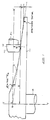
- Figure 1 shows a first transmission element 10 engaged with a second transmission element 12.
- the transmission element 10 is generally disc shaped and has a profiled contact face 14 formed on one major surface thereof which engages a complementally profiled face 16 formed on the periphery of the second transmission element 12, which is generally cylindrical.
- the transmission element 10 is mounted on a shaft 18, while the transmission element 12 is mounted on a shaft 20 which is orthogonal to the shaft 18.
- the transmission element 12 is slideable axially so that it makes contact with the element 10 at a point C at a variable distance X from the axis of the shaft 18.
- the second transmission element 12 serve as an input pinion, and that the transmission element 10 serve as an output gear. It will thus be appreciated that the illustrated transmission has a reduction ratio which will depend on the distance X of the contact point C from-the axis Y-Y. If the respective profiles of the transmission elements 10 and 12 are selected so that pure rolling contact takes place between the elements, then the losses and wear associated with simple friction transmission systems can be avoided.
- both CA and BA are equal to the radius of curvature r.
- the profile can be represented by a large number of small right angled triangles, each ⁇ x wide.
- the difference in height, ⁇ y is given by and as ⁇ x ⁇ dx, the height t, for values of x between u and s, becomes
- Figures 4 and 5 illustrate an example of the calculated profiles of an input transmission element 12 and an output transmission element 10, respectively.
- the profile of the transmission element 10 was calculated by means of a suitable computer programme on an HP 15c programmable calculator.
- the gear ratio range of the described transmission system can be relatively high. For example, a ratio of 5:1 is possible.
- the size of the transmission elements may be limited by the speeds at which they are operated. Using transmission elements of hardened and ground steel, running with trace oil lubrication, rolling velocities of 30 to 50 m/s are possible. This places a constraint on the size of the elements, if hoop stresses in the elements are to be limited to an acceptable value.
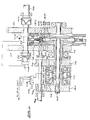
- FIG. 6 is a schematic illustration of a practical transmission unit according to the invention.
- An input shaft 48 from a vehicle clutch (not shown) transmits drive torque to a pair of pinions 50 and 52, which are mounted on a common shaft 54.
- the pinions 50 and 52 drive further pinions 54 and 56, respectively, which are in turn connected to respective gallery gears 58 and 60.
- the gallery gears define annular ring gears 62 which face inwardly.
- a reversing idler (not shown) between the pinions 52 and 56 causes the gallery gear 60 to be driven in the opposite direction to the gallery gear 58.
- the gallery gears 58 and 60 drive a set of twelve pinions 64 which are arranged radially about the central axis of the transmission.
- Each pinion 62 can slide on a splined shaft 66.
- Fixed to the inner end of each shaft 66 is an input transmission element 68, as described above, which is held in engagement with the profiled faces of a pair of output transmission elements 70 and 72.
- the transmission elements 70 and 72 have respective shafts 74 and 76, the shaft 74 being tubular and the shaft 76 being disposed coaxially therewithin.
- Respective pinions 78 and 80 are fixed to the shafts 74 and 76.
- the shaft 76 has a splined end 82 on which the pinion 80 is fixed.
- the shafts 74 and 76 are mounted to be axially slideable relative to one another under the urging of an annular hydraulic cylinder 84.
- the cylinder 84 is double acting and comprises a pair of pistons 86 and 88 which apply axial force to the pinions 78 and 80, respectively, via respective tapered roller bearings 90 and 92.
- a compression coil spring 93 biases the pistons 86 and 88 apart.
- Urging of the pinions 78 and 80 apart under the influence of the hydraulic cylinder 84 moves the shafts 74 and 76 relative to one another, to cause the output transmission elements 70 and 72 to be urged together.
- the degree of force generated by the hydraulic cylinder 84 is related to the input torque to the transmission unit applied via the shaft 48.
- a torque sensor 100 controls the operation of a hydraulic system which varies the pressure in the hydraulic cylinder 84 according to the magnitude of the input torque.
- the torque sensor 100 comprises a coupling having two halves which are axially displacable relative to one another if the input torque applied to the coupling is great enough.
- the shaft 54 is forced axially away from the torque sensor 100 and pushes a piston 102 into a cylinder 104.
- the cylinder 104 is pressurised by a hydraulic pump 106 which is driven constantly by the shaft 54. Assuming that the transmission unit is on load, a load/unload valve 106 connects the output of the cylinder 104 to the hydraulic cylinder 84, so that the input torque surge causes the transmission elements 70 and 72 to be urged more strongly together.
- the load/unload valve 106 is controlled by a cam 108 and switches the drive from the illustrated transmission unit to a second transmission unit (not shown) as required. Even when the load/unload valve has been operated to take the transmission unit off load, the compression spring 93 provides sufficient force to keep the input transmission element 68 and the output transmission elements 70, 72 in frictional contact.
- the pinions 78 and 80 are connected via intervening pinions 94 and 96 to an output shaft 98 of the transmission.
- a reversing idler between the pinions 80 and 96 translates the drive from the counter-rotating shafts 74 and 76 into the same direction of rotation.
- Figure 7 illustrates a control mechanism which controls the radial positions of the transmission elements 68 relative to the axis of the transmission elements 70 and 72.
- the device essentially comprises a pair of ris cam elements 150 and 152 which take the form of annular elements arranged side by side, concentrically about the gallery gears 58 and 60, and having curved grooves 154 cut in their opposed inner faces.
- the grooves 154 receive respective ends of follower blocks 156 which are fitted to the end of each splined shaft 66, so that the follower blocks are slideable in the grooves.
- the iris cams are linked, and can be rotated about the axis of the output transmission elements 70 and 72 by a control rod 158.
- the control rod 158 is actuated by a mechanism which can be hydraulically driven and which is, in turn, controlled by an external control system in accordance with predetermined operating parameters, as referred to below.
- the described transmission unit is essentially a friction drive system, but does not suffer from the losses of known systems. Because of the number of input transmission elements (twelve), each of which drives two output elements, the transmission unit is capable of handling greater torques than simple systems.
- the complementary profiles of the input and output transmission elements allow the transmission ratio to be steplessly varied, on or off load.
- the transmission ratio range of the above described transmission unit will typically be approximately 1,5:1, in a unit which can handle sufficient torque and operate at sufficiently high speeds for use in a motor vehicle.
- a typical motor vehicle transmission for use in a passenger vehicle with an internal combustion engine may require a transmission ratio range of from 4:1 to 5:1. It is thus necessary, in such applications, to provide an auxiliary transmission or gearbox which augments the transmission ratio range of the basic transmission unit.
- two transmission units are combined with an auxiliary transmission unit which connects the transmission units alternately in a "leap frog" manner, so that a steplessly variable transmission is effectively provided.
- the transmission includes identical first and second.continuously variable transmission units 110 and 112 as described above. Note that, for clarity, the transmission units 110 and 112 are shown as having opposed output shafts extending on either side of the units, in contrast with the arrangment shown in Figure 6, where concentric output shafts 74 and 76 are shown. The arrangement of Figure 6 is more compact, but the arrangement in Figure 8 is easier to follow.
- the transmission units 110 and 112 are arranged to be driven from a common input shaft 114, and drive respective first and second intermediate output shafts 116 and 118.
- the shaft 118 is driven via different ratio gearing from the shaft 116, so that it rotates at a speed which is 1,5 times higher than that of the shaft 116. This corresponds to the ratio range of the transmission units 110 and 112.
- first and second pinions 120 and 122 On the shaft 116 are disposed first and second pinions 120 and 122, which can rotate freely about the shaft 116.
- a selector unit 124 is engaged with splines 126 on the shaft 116 and is slideable axially on the shaft by a selector fork (not shown).
- pinions 128 and 130 are disposed on the shaft 118, and can be selected by means of a selector unit 132.
- the drive will be passed from the intermediate output shaft 116 or 118 to a final output shaft 134 via respective output pinions 136 and 138.
- the transmission ratio between the input shaft 114 and the output shaft 134 will depend on the drive ratio of the transmission unit 110 or 112 which is engaged, and which of the pinions 120, 122, 128 or 130 is engaged with the pinions 136 or 138.
- the pinions 122 and 130 have a ratio with the pinion 138 which is a factor 1,5 2 or 2,25 greater than that of the pinions 120 or 128 with the pinion 136.
- one of the pinions 120, 122, 128 or 130 be selected as the associated transmission unit 110 or 112 reaches the limit of its transmission ratio range. Because this range corresponds to the ratio between the speeds of the intermediate output shafts 116 and 118, drive can be transferred from the pinions 120 or 122 to the pinions 128 or 130, or vice versa, without any further synchronisation being necessary. It can be noted that as drive is transferred from one transmission unit to the other, there is a momentary overlap period when both units are engaged, the respective units being at the top and bottom of their ratio ranges.
- a steplessly variable transmission can be obtained which has a transmission range which is considerably greater than that of a single transmission unit 110 or 112 alone.
- the transmission system of the invention is preferably used in conjunction with a control system which continuously adjusts the overall transmission ratio of, for example, a motor vehicle in accordance with predetermined criteria. For example, it can be calculated that, for a given throttle opening, an internal combustion engine is most efficient at a particular engine speed.
- the control system can be calibrated to vary the effective transmission ratio in order to maintain the engine speed constant as the load on the engine varies. If, for example, the accelerator were to be depressed further, a different engine speed would be selected, and the transmission would adjust its ratio accordingly.
- fully automatic operation of the vehicle is obtained, it being necessary only to provide a manual clutch for starting off and stopping.
- control system for the transmission may be operated, for example, electrically, hydraulically or mechanically.
- the preferred solution will depend largely on the cost and reliability of the control system.
Landscapes
- Engineering & Computer Science (AREA)
- General Engineering & Computer Science (AREA)
- Mechanical Engineering (AREA)
- Friction Gearing (AREA)
- Transmission Devices (AREA)
Claims (15)
- Regelbare Getriebeeinheit, die wenigstens ein erstes Getriebeelement (10; 70, 72) einschliesst, das zur Drehung um eine erste Achse (Y-Y) angebracht und das längs seiner Achse axial gleitbar angebracht ist, und wenigstens ein zweites Getriebeelement (12; 68) in Berührung mit dem ersten Element, und das zur Drehung um eine zweite Achse (X-X) angebracht ist, die einen vorbestimmten Winkel mit der ersten Achse definiert, dadurch gekennzeichnet, dass das zweite Getriebeelement längs der zweiten Achse axial gleitbar ist, um die Entfernung (x) zwischen dem Berührungspunkt (c) der Getriebeelemente und der ersten Achse zu regeln, und dabei das effektive Getriebeübersetzungsverhältnis zu regeln, wobei die ersten und zweiten Elemente mit komplementär profilierten, sich berührenden Flächen (14, 16) vorgesehen sind, so dass die gemeinsame Tangente an dem Berührungspunkt durch den Schnittpunkt der ersten und zweiten Achsen geht, ungeachtet der Axialstellung des zweiten Getriebeelements, wobei die Relativbewegung zwischen den Getriebeelementen im wesentlichen Rollbewegung ist.
- Getriebeeinheit nach Anspruch 1, dadurch gekennzeichnet, dass die ersten und zweiten Achsen (Y-Y, X-X) orthogonal sind.
- Getriebeeinheit nach Anspruch 1 oder Anspruch 2, dadurch gekennzeichnet, dass das erste Getriebeelement (10; 70, 72) im allgemeinen scheibenförmig ist, wobei die profilierte Berührungsfläche (14) auf einer Hauptoberfläche davon liegt, das zweite Getriebeelement (12; 68) im allgemeinen zylindrisch ist und die komplementär profilierte Berührungsfläche (16) auf seiner Peripherie hat.
- Getriebeeinheit nach Anspruch 3, dadurch gekennzeichnet, dass eine Vielzahl der zweiten Getriebeelemente (68) neben den ersten Getriebeelementen (70, 72) angeordnet und radial um die erste Achse verteilt sind, wobei jedes zweite Getriebeelement in Antriebsverbindung mit einem weiteren gemeinsamen Getriebeelement (58, 60) steht.
- Getriebeeinheit nach Anspruch 4, dadurch gekennzeichnet, dass jedes zweite Getriebeelement (68) angeordnet ist, um von einem Ritzel (64) angetrieben zu werden, wobei das gemeinsame Getriebeelement (58, 60) einen Zahnkranz (62) hat, der die Ritzel (64) antreibt.
- Getriebeeinheit nach Anspruch 5, dadurch gekennzeichnet, dass jedes zweite Getriebeelement (68) an einer kerbverzahnten Welle (66) befestigt ist, auf welcher das entsprechende Ritzel (64) axial gleitbar ist, so dass das zweite Getriebeelement radial relativ zu der ersten Achse der Getriebeeinheit verschoben werden kann, während die Radialstellung des Ritzels (64) konstant bleibt.
- Getriebeeinheit nach einem der Ansprüche 4 bis 6, dadurch gekennzeichnet, dass ein Paar von ersten Getriebeelementen (70, 72) einander gegenüber angeordnet sind, wobei die zweiten Getriebeelementen dazwischen in Antriebsverbindung mit beiden ersten Getriebeelementen angeordnet sind.
- Getriebeeinheit nach Anspruch 7, dadurch gekennzeichnet, dass ein Drehmomentabtastmittel (100) vorgesehen ist, das ein Ausgangssignal liefert, das auf das Eingangsdrehmoment zu der Getriebeeinheit bezogen ist, und ein auf das Ausgangssignal reagierendes Vorspannungsmittel (84, 102, 104) ist vorgesehen, um die beiden ersten Getriebeelemente (70, 72) mit einer Kraft zusammenzudrängen, die auf die Grösse des Eingangsdrehmomentes bezogen ist.
- Getriebeeinheit nach Anspruch 7 oder Anspruch 8, dadurch gekennzeichnet, dass jedes erste Getriebeelement (70, 72) mit einer entsprechenden Hilfsabtriebswelle (76, 74) verbunden ist, wobei die beiden Hilfsabtriebswellen sich in Bezug aufeinander gegenläufig drehen, wobei eine Hilfsabtriebswelle durch ein rückwärtsgehendes Zwischenrad an eine gemeinsame Hauptabtriebswelle (98) angeschlossen ist, und die andere Hilfsabtriebswelle direkt an die Hauptabtriebswelle angeschlossen ist.
- Getriebeeinheit nach einem der Ansprüche 6 bis 9, dadurch gekennzeichnet, dass jede kerbverzahnte Welle (66) von einem Stössel (156) getragen wird, der in einem Einstellungsmechanismus (150, 152, 154) angebracht ist, wobei der Einstellungsmechanismus betreibbar ist, um die Radialstellung des Stössels, und daher des zweiten Getriebeelementes (68) relativ zu der ersten Achse in Reaktion auf ein Kontrollsignal zu regeln.
- Getriebeeinheit nach Anspruch 10, dadurch gekennzeichnet, dass der Einstellungsmechanismus (150, 152, 154) ein Paar von ringförmigen Platten (150, 152) umfasst, die konzentrisch um die erste Achse neben dem ersten Getriebeelement (70, 72) angeordnet sind, wobei gegenüberliegende Flächen der ringförmigen Platten geneigte Spalten (154) definieren, in denen entsprechende Stössel (156) aufgenommen werden, wobei ein Einstellungsmittel (158) vorgesehen ist, um die Platten relativ zu der ersten Achse zu drehen, um dabei Radialbewegung der Stössel relativ zu der ersten Achse zu verursachen.
- Getriebeeinheit nach Anspruch 10 oder Anspruch 11, dadurch gekennzeichnet, dass die Getriebeeinheit von einem Verbrennungsmotor angetrieben wird, das Kontrollsignal von einer Motordrosseleinstellung oder einer äquivalenten Einstellung und von einem vorbestimmten Verhältnis zwischen Motorgeschwindigkeit und Drosseleinstellung abgeleitet wird, so dass das Kontrollsignal verursacht, dass die Stellung der ersten Getriebeelemente (70, 72) eingestellt werden, um eine im wesentlichen konstante Motorgeschwindigkeit für eine gegebene Drosseleinstellung unabhängig von der Ausgangslast auf dem Getriebe beizubehalten.
- Getriebe für ein Fahrzeug, das erste und zweite Getriebeeinheiten (110, 112) nach einem der Ansprüche 1 bis 12 umfasst, dadurch gekennzeichnet, dass die Getriebeeinheiten angeordnet sind, um von einer gemeinsamen Antriebswelle (114) angetrieben zu werden, wobei die Ausgänge der Getriebeeinheiten auf entsprechende erste und zweite Hilfsabtriebswellen (116, 118) weitergegeben werden, wobei die zweite Hilfsabtriebswelle (118) angeordnet ist, um sich mit einer Geschwindigkeit zu drehen, die um einen, dem Übersetzungsverhältnisbereich der Getriebeeinheiten gleichen Faktor höher als die der ersten Hilfsabtriebswelle (116) ist, wobei der Antrieb von einer oder der anderen der Hilfsabtriebswellen an eine Endabtriebswelle (134) durch eine Vielzahl von wahlweise in Eingriff bringbare Ritzel (120, 122, 128, 130), die jeder Hilfswelle zugeordnet sind, übertragen wird.
- Getriebe für ein Fahrzeug nach Anspruch 13, dadurch gekennzeichnet, dass ein Paar von Ritzeln verschiedener Grösse auf jeder Hilfsabtriebswelle (116, 118) angebracht ist, und ein Gangwähler (124, 132) vorgesehen ist, der in die Welle eingreift und axial darauf gleitbar ist, um in eines der anderen Ritzel (120, 122, 128, 130) einzugreifen.
- Getriebe für ein Fahrzeug nach Anspruch 13 oder Anspruch 14, dadurch gekennzeichnet, dass es ein Mittel zum automatischen Kontrollieren des Betriebes des Getriebes einschliesst, so dass der Antrieb von einer Hilfsabtriebswelle (116, 118) zu der anderen übertragen wird, wenn das entsprechende Getriebe (110, 112) die Grenze seines übersetzungsverhältnisbereiches erreicht, so dass ein stufenlos regelbarer Antrieb über einem Übersetzungsverhältnisbereich erhalten wird, der grösser als derjenige einer der Getriebeeinheiten allein ist.
Priority Applications (1)
| Application Number | Priority Date | Filing Date | Title |
|---|---|---|---|
| AT89307597T ATE81192T1 (de) | 1988-07-27 | 1989-07-26 | Regelbares getriebe. |
Applications Claiming Priority (4)
| Application Number | Priority Date | Filing Date | Title |
|---|---|---|---|
| ZA885486 | 1988-07-27 | ||
| ZA885486 | 1988-07-27 | ||
| ZA885485 | 1988-07-27 | ||
| ZA885485 | 1988-07-27 |
Publications (2)
| Publication Number | Publication Date |
|---|---|
| EP0356015A1 EP0356015A1 (de) | 1990-02-28 |
| EP0356015B1 true EP0356015B1 (de) | 1992-09-30 |
Family
ID=27139307
Family Applications (1)
| Application Number | Title | Priority Date | Filing Date |
|---|---|---|---|
| EP89307597A Expired - Lifetime EP0356015B1 (de) | 1988-07-27 | 1989-07-26 | Regelbares Getriebe |
Country Status (4)
| Country | Link |
|---|---|
| US (1) | US5014565A (de) |
| EP (1) | EP0356015B1 (de) |
| JP (1) | JPH02146355A (de) |
| DE (1) | DE68903075T2 (de) |
Families Citing this family (8)
| Publication number | Priority date | Publication date | Assignee | Title |
|---|---|---|---|---|
| US5520592A (en) * | 1994-02-25 | 1996-05-28 | Rabinow; Jacob | Balanced force anti-spin friction drive |
| US5407399A (en) * | 1994-02-25 | 1995-04-18 | Rabiniow; Jacob | Variable speed friction transmission |
| US6260654B1 (en) * | 1998-02-06 | 2001-07-17 | Nsk Ltd. | Frictional transmission |
| US6676560B1 (en) | 2001-02-15 | 2004-01-13 | Terry Buelna | Continuously variable transmission |
| US7351181B2 (en) * | 2004-06-28 | 2008-04-01 | Robert Smith | Continuously variable transmission |
| JP5037954B2 (ja) * | 2007-01-15 | 2012-10-03 | ヤマハ発動機株式会社 | ベルト式無段変速機および車両 |
| US8152688B2 (en) * | 2008-05-16 | 2012-04-10 | Terry Buelna | Compensator for continuously variable transmission |
| US11655880B2 (en) | 2020-07-08 | 2023-05-23 | Lockheed Martin Corporation | Multi-speed gear box for a rotary wing aircraft |
Family Cites Families (4)
| Publication number | Priority date | Publication date | Assignee | Title |
|---|---|---|---|---|
| GB1093242A (en) * | 1964-05-26 | 1967-11-29 | Silentbloc Australia Proprieta | Improvements in infinitely variable speed transmission apparatus |
| JPS4927762A (de) * | 1972-06-30 | 1974-03-12 | ||
| FR2366492A1 (fr) * | 1976-09-30 | 1978-04-28 | Virlon Jean Claude | Perfectionnements apportes aux dispositifs de transmission de vitesse |
| US4466312A (en) * | 1980-05-27 | 1984-08-21 | Aisin Seiki Kabushiki Kaisha | System for controlling transmission ratio of transmission for automotive vehicles |
-
1989
- 1989-07-26 EP EP89307597A patent/EP0356015B1/de not_active Expired - Lifetime
- 1989-07-26 DE DE8989307597T patent/DE68903075T2/de not_active Expired - Fee Related
- 1989-07-27 US US07/385,421 patent/US5014565A/en not_active Expired - Fee Related
- 1989-07-27 JP JP1197899A patent/JPH02146355A/ja active Pending
Also Published As
| Publication number | Publication date |
|---|---|
| EP0356015A1 (de) | 1990-02-28 |
| DE68903075T2 (de) | 1993-04-22 |
| DE68903075D1 (de) | 1992-11-05 |
| US5014565A (en) | 1991-05-14 |
| JPH02146355A (ja) | 1990-06-05 |
Similar Documents
| Publication | Publication Date | Title |
|---|---|---|
| AU682914B2 (en) | Continuously variable transmission capable of torque control | |
| CA1316374C (en) | Hydraulic control circuits for continuously-variable-ratio transmissions | |
| EP0447801B1 (de) | Mechanisch verstellbares Getriebe | |
| US5184981A (en) | Cam loaded continuously variable transmission | |
| EP0466113B1 (de) | Stufenloses Reibrollengetriebe | |
| US5338268A (en) | Toroidal-race rolling-traction type transmission | |
| Kluger et al. | An overview of current CVT mechanisms, forces and efficiencies | |
| EP1053415B1 (de) | Stufenloses getriebe mit gangsynchronisiereinrichtung | |
| US5014565A (en) | Variable ratio transmission | |
| CN88103055A (zh) | 连续变速传动 | |
| US5013288A (en) | Transmission systems | |
| EP0416492B1 (de) | Stufenloses Getriebe | |
| EP0305110A2 (de) | Getriebeeinrichtung | |
| US4192200A (en) | Variable ratio gear transmission | |
| EP3074662B1 (de) | Verdichter-einrichtung | |
| US3453904A (en) | Transmission mechanism for automobile vehicles and the like | |
| US4501574A (en) | Transmission ratio variators | |
| US4682517A (en) | Variable speed drive--apparatus and method of fabricating the apparatus | |
| US4590815A (en) | Multiple cone type variable power transmission mechanism | |
| EP0330447B1 (de) | Gerät zur stufenlosen Geschwindigkeitsänderung | |
| US4745821A (en) | Speed ratio adjusting system for nutational traction drive transmissions | |
| KR100313808B1 (ko) | 벨트식 무단 변속기의 무단 변속기구 | |
| RU2052688C1 (ru) | Многодисковая бесступенчатая фрикционно-зубчатая передача | |
| WO1992018791A1 (en) | Continuously variable transmission with torque regeneration | |
| WO2021014194A1 (en) | Variable diameter shaft continuously variable transmission (vds.cvt) |
Legal Events
| Date | Code | Title | Description |
|---|---|---|---|
| PUAI | Public reference made under article 153(3) epc to a published international application that has entered the european phase |
Free format text: ORIGINAL CODE: 0009012 |
|
| AK | Designated contracting states |
Kind code of ref document: A1 Designated state(s): AT BE DE FR GB IT NL SE |
|
| 17P | Request for examination filed |
Effective date: 19900823 |
|
| 17Q | First examination report despatched |
Effective date: 19910425 |
|
| GRAA | (expected) grant |
Free format text: ORIGINAL CODE: 0009210 |
|
| AK | Designated contracting states |
Kind code of ref document: B1 Designated state(s): AT BE DE FR GB IT NL SE |
|
| PG25 | Lapsed in a contracting state [announced via postgrant information from national office to epo] |
Ref country code: AT Effective date: 19920930 |
|
| REF | Corresponds to: |
Ref document number: 81192 Country of ref document: AT Date of ref document: 19921015 Kind code of ref document: T |
|
| REF | Corresponds to: |
Ref document number: 68903075 Country of ref document: DE Date of ref document: 19921105 |
|
| ITF | It: translation for a ep patent filed | ||
| ET | Fr: translation filed | ||
| PLBE | No opposition filed within time limit |
Free format text: ORIGINAL CODE: 0009261 |
|
| STAA | Information on the status of an ep patent application or granted ep patent |
Free format text: STATUS: NO OPPOSITION FILED WITHIN TIME LIMIT |
|
| 26N | No opposition filed | ||
| EAL | Se: european patent in force in sweden |
Ref document number: 89307597.8 |
|
| PGFP | Annual fee paid to national office [announced via postgrant information from national office to epo] |
Ref country code: FR Payment date: 19960709 Year of fee payment: 8 |
|
| PGFP | Annual fee paid to national office [announced via postgrant information from national office to epo] |
Ref country code: SE Payment date: 19960717 Year of fee payment: 8 Ref country code: GB Payment date: 19960717 Year of fee payment: 8 |
|
| PGFP | Annual fee paid to national office [announced via postgrant information from national office to epo] |
Ref country code: NL Payment date: 19960729 Year of fee payment: 8 |
|
| PGFP | Annual fee paid to national office [announced via postgrant information from national office to epo] |
Ref country code: DE Payment date: 19960802 Year of fee payment: 8 |
|
| PGFP | Annual fee paid to national office [announced via postgrant information from national office to epo] |
Ref country code: BE Payment date: 19960911 Year of fee payment: 8 |
|
| PG25 | Lapsed in a contracting state [announced via postgrant information from national office to epo] |
Ref country code: GB Free format text: LAPSE BECAUSE OF NON-PAYMENT OF DUE FEES Effective date: 19970726 |
|
| PG25 | Lapsed in a contracting state [announced via postgrant information from national office to epo] |
Ref country code: SE Effective date: 19970727 |
|
| PG25 | Lapsed in a contracting state [announced via postgrant information from national office to epo] |
Ref country code: BE Free format text: LAPSE BECAUSE OF NON-PAYMENT OF DUE FEES Effective date: 19970731 |
|
| BERE | Be: lapsed |
Owner name: SWANEPOEL PAUL JACOBUS Effective date: 19970731 Owner name: STEPHENSON PETER Effective date: 19970731 |
|
| PG25 | Lapsed in a contracting state [announced via postgrant information from national office to epo] |
Ref country code: NL Free format text: LAPSE BECAUSE OF NON-PAYMENT OF DUE FEES Effective date: 19980201 |
|
| GBPC | Gb: european patent ceased through non-payment of renewal fee |
Effective date: 19970726 |
|
| PG25 | Lapsed in a contracting state [announced via postgrant information from national office to epo] |
Ref country code: FR Free format text: LAPSE BECAUSE OF NON-PAYMENT OF DUE FEES Effective date: 19980331 |
|
| NLV4 | Nl: lapsed or anulled due to non-payment of the annual fee |
Effective date: 19980201 |
|
| PG25 | Lapsed in a contracting state [announced via postgrant information from national office to epo] |
Ref country code: DE Free format text: LAPSE BECAUSE OF NON-PAYMENT OF DUE FEES Effective date: 19980401 |
|
| EUG | Se: european patent has lapsed |
Ref document number: 89307597.8 |
|
| REG | Reference to a national code |
Ref country code: FR Ref legal event code: ST |
|
| PG25 | Lapsed in a contracting state [announced via postgrant information from national office to epo] |
Ref country code: IT Free format text: LAPSE BECAUSE OF NON-PAYMENT OF DUE FEES Effective date: 20050726 |