EP0356053A2 - Système de visualisation - Google Patents
Système de visualisation Download PDFInfo
- Publication number
- EP0356053A2 EP0356053A2 EP89307978A EP89307978A EP0356053A2 EP 0356053 A2 EP0356053 A2 EP 0356053A2 EP 89307978 A EP89307978 A EP 89307978A EP 89307978 A EP89307978 A EP 89307978A EP 0356053 A2 EP0356053 A2 EP 0356053A2
- Authority
- EP
- European Patent Office
- Prior art keywords
- display
- range
- area
- value
- array
- Prior art date
- Legal status (The legal status is an assumption and is not a legal conclusion. Google has not performed a legal analysis and makes no representation as to the accuracy of the status listed.)
- Withdrawn
Links
- 238000000034 method Methods 0.000 claims description 10
- 230000008569 process Effects 0.000 claims description 3
- 238000007781 pre-processing Methods 0.000 abstract description 3
- 239000000523 sample Substances 0.000 description 31
- 238000012545 processing Methods 0.000 description 7
- 238000013459 approach Methods 0.000 description 6
- 238000010586 diagram Methods 0.000 description 6
- 238000003491 array Methods 0.000 description 5
- 230000008901 benefit Effects 0.000 description 3
- 230000006872 improvement Effects 0.000 description 3
- 238000005070 sampling Methods 0.000 description 3
- 238000012360 testing method Methods 0.000 description 3
- 238000007792 addition Methods 0.000 description 1
- 238000004458 analytical method Methods 0.000 description 1
- 230000005540 biological transmission Effects 0.000 description 1
- 230000008859 change Effects 0.000 description 1
- 238000004891 communication Methods 0.000 description 1
- 230000006854 communication Effects 0.000 description 1
- 230000000694 effects Effects 0.000 description 1
- 239000004973 liquid crystal related substance Substances 0.000 description 1
- 230000007246 mechanism Effects 0.000 description 1
- 238000012986 modification Methods 0.000 description 1
- 230000004048 modification Effects 0.000 description 1
- 239000007787 solid Substances 0.000 description 1
- 230000000007 visual effect Effects 0.000 description 1
Images


Classifications
-
- G—PHYSICS
- G09—EDUCATION; CRYPTOGRAPHY; DISPLAY; ADVERTISING; SEALS
- G09G—ARRANGEMENTS OR CIRCUITS FOR CONTROL OF INDICATING DEVICES USING STATIC MEANS TO PRESENT VARIABLE INFORMATION
- G09G1/00—Control arrangements or circuits, of interest only in connection with cathode-ray tube indicators; General aspects or details, e.g. selection emphasis on particular characters, dashed line or dotted line generation; Preprocessing of data
- G09G1/06—Control arrangements or circuits, of interest only in connection with cathode-ray tube indicators; General aspects or details, e.g. selection emphasis on particular characters, dashed line or dotted line generation; Preprocessing of data using single beam tubes, e.g. three-dimensional or perspective representation, rotation or translation of display pattern, hidden lines, shadows
- G09G1/14—Control arrangements or circuits, of interest only in connection with cathode-ray tube indicators; General aspects or details, e.g. selection emphasis on particular characters, dashed line or dotted line generation; Preprocessing of data using single beam tubes, e.g. three-dimensional or perspective representation, rotation or translation of display pattern, hidden lines, shadows the beam tracing a pattern independent of the information to be displayed, this latter determining the parts of the pattern rendered respectively visible and invisible
- G09G1/16—Control arrangements or circuits, of interest only in connection with cathode-ray tube indicators; General aspects or details, e.g. selection emphasis on particular characters, dashed line or dotted line generation; Preprocessing of data using single beam tubes, e.g. three-dimensional or perspective representation, rotation or translation of display pattern, hidden lines, shadows the beam tracing a pattern independent of the information to be displayed, this latter determining the parts of the pattern rendered respectively visible and invisible the pattern of rectangular co-ordinates extending over the whole area of the screen, i.e. television type raster
- G09G1/162—Control arrangements or circuits, of interest only in connection with cathode-ray tube indicators; General aspects or details, e.g. selection emphasis on particular characters, dashed line or dotted line generation; Preprocessing of data using single beam tubes, e.g. three-dimensional or perspective representation, rotation or translation of display pattern, hidden lines, shadows the beam tracing a pattern independent of the information to be displayed, this latter determining the parts of the pattern rendered respectively visible and invisible the pattern of rectangular co-ordinates extending over the whole area of the screen, i.e. television type raster for displaying digital inputs as analog magnitudes, e.g. curves, bar graphs, coordinate axes, singly or in combination with alpha-numeric characters
Definitions
- the invention relates to display systems for representing arrays of data values in a display field.
- the display field of a display system may take the form of the screen of a device such as a cathode ray tube or a liquid crystal display, or possibly also the print field of a printer.
- the data for display may be stored by the display device itself as would be the case in a storage tube, or it may be held in refresh storage for, for example, a cathode ray tube device. Either way, a mechanism has to be provided in order to specify the actual location within the display field at which a particular piece of information is to be displayed. In digital systems, this is done by dividing the display field into an array of pixel positions which can be addressed. This means that the display field is quantised and raises problems in the case where an array of data values to be represented is large and consequently has a finer definition than is provided by the quantisation of the display field.
- the object the invention is to improve the plotting performance of a display system for representing large arrays of data values in a display field.
- a display system comprising means for representing an array of data values in a display field, said means comprising:
- the invention recognises that the overplotting in the display field which was performed in prior art display systems was inefficient and time consuming due to the time taken to write data into the display field (eg, plotting values in a display buffer) and provides for the preprocessing of data values in the data array to reduce the number of plots made in the display field.
- the advantages of the invention are particularly apparent in the case of large arrays of data values, the invention is not limited to the processing of large arrays only.
- the range storage for a display area comprises a maximum and a minimum register. After the ranging logic has processed the data values of the data array, the maximum and minimum registers for a display area will contain the maximum and minimum values, respectively, of the range for that area.
- the display system additionally comprises secondary plotting logic for determining whether a maximum value in the range for a display area is lower than a minimum value in an adjacent display area and, in the case where the determination is positive, for plotting an additional line joining display screen positions defined by said maximum and minimum values for those areas.
- This secondary plotting logic enhances the representation of the array of data values in the case where the number of samples per display areas is not very high (eg. 1 to 5 samples per display area).
- the display system may additionally comprise initialisation logic for setting the range storage to an invalid range and the ranging logic be arranged to be responsive to an invalid range when comparing a value to the range defined by the range storage for a display area to replace the invalid range with said value.
- An invalid range could be represented, for example, by storing maximum and minimum values in the range storage where the value for the minimum is larger than the value for the maximum.
- the initial storage of an invalid range is not essential, however, and the initialisation logic may merely comprise means for presetting the range storage to a predetermined value, (eg. the expected median value for a speech waveform). This latter approach is adopted in the particular embodiment to be described later.
- a predetermined value eg. the expected median value for a speech waveform
- each display area is a strip within the display field.
- the display field comprises an array of pixel positions and each strip is one pixel position wide.
- a display system as defined above can form part of a waveform analyser.
- the array of data values to be displayed on a display screen is a one dimensional array comprising samples of a waveform to be analysed.
- the array of data values is usually in the form of a data stream and the display system is adapted to process the data stream serially.
- FIG. 1 is a schematic illustration of a speech waveform 10 as seen on a display screen 12 of a display system.
- the speech waveform represented here is for the expression "We were away” said in 1.06 seconds.
- the speech is sampled at a rate of 10,000 samples per second, which means that the waveform shown comprises 10,600 samples.
- successive samples are displayed along the horizontal direction with the sample values themselves allocated to the y coordinates and a line drawn between each (x,y) point and its neighbour.
- FIG. 2 gives an overview of part of a display system in accordance with the invention.
- the display system in turn forms part of a speech analyser (not shown) which provides a stream of speech samples at an input 14 to ranging logic 16.
- the speech samples are supplied to the input 14 of the ranging logic 16 in chronological order.
- the ranging logic 16 is operative to determine for each sample, an area of a display field within which that value should be displayed.
- the display field corresponds to the visible part of the display screen.
- it could alternatively relate to a virtual screen or presentation space for a window for display, or to the area of a buffer for printing or facsimile transmission, and the like.
- the present display system is adapted to display a speech waveform which is represented by a one dimensional data array (ie, a string of data values) in the form of the data stream on a pixel based display screen with time plotted along the x axis.
- the display field is logically divided into display areas in the form of vertical strips, each of one pixel width.
- Range storage 18 comprises storage (eg. Imax, Imin) for an indication of a range of values for each area (eg. the Ith area) of the display field. As shown in Figure 2, a pair of storage locations (eg Imax, Imin) is provided for each vertical row of pixels for storing a maximum and a minimum value, respectively, for that vertical row of pixels.
- the ranging logic is also operative, having determined an area of a display field (eg. the Ith area) within which that value should be displayed, to compare the value of that sample to the range of values defined by the range storage (eg Imax, Imin) for the area in question.
- the ranging logic updates the range defined by the range storage for that area to include the value of the sample if it lies outside the range previously defined for the area.
- step 28 therefore, on processing each sample, the value N is added to the existing error value, e, and the new e value is tested to determine whether it is greater than m/2. If the new error value, e, is less than or equal to m/2, this means that the current sample is associated with the current display area. If, however, the error value, e, is greater than m/2 this indicates that all the samples for the display area, b, have been processed, and consequently, the number of the current display area, b, is incremented. In this case the error value, e, is also adjusted to take account of the change of the display area number by subtracting the value m from the current error value, e.
- the technique is analogous to the Bresenham line drawing algorithm and has the effect of evenly distributing the samples within the various areas of the display field when L/C is not an integer. It also has the advantage that it requires no time consuming multiply operations, and can therefore be implemented efficiently in assembly language.
- the sample storage can take the form of a table comprising a maximum and minimum register for each of the display areas.
- the registers may be special purpose registers or may be implemented by suitably configuring general purpose storage.
- the selection of the registers for a display area can be made using the display area number, b, as an element of an address for the registers (eg. as an index from a base address for the first register in the range storage).
- the appropriate register, or registers can be updated, in step 34, by replacing the previous values stored in the register with the new sample value. If the new sample value lies within the range stored in the range register, then the new sample value is discarded and the range is not updated.
- an alternative approach would be initially to set the range values to an invalid range (eg. with the minimum value larger that the maximum value), and to test for this in step 32 when comparing a new sample value to the values stored for a range. If then, an invalid range is found, this means that the sample being processed is the first sample for that display area and the new sample value is to be stored in both the maximum and minimum registers for the current display area.
- step 26 If, on returning to step 26, there is a further sample to be processed, then the steps 28 to 34 are repeated for the next sample. Otherwise, the processing by the ranging logic is complete, at 36.
- plotting logic 20 is provided for accessing range storage 18 for plotting a line within each display area between display field positions corresponding to the maximum and minimum values indicated by the appropriate locations in the range storage.
- the operation of the plotting logic is illustrated in Figure 4.
- the plotting logic is initialised at step 40 with a pointed to the range registers for the first area.
- the plotting logic then accesses the pair of storage locations for the first area at step 44 and plots, at step 46, a line between the display positions represented by the range values stored in those registers.
- the step 46 of plotting a line comprises writing appropriate values into locations in the display buffer 22 for causing a line to be displayed at the position in the X direction which extends between the maximum and minimum Y positions indicated by the values in the maximum and minimum storage locations for that X position. If, on returning to step 42, there is a further display area to be processed, then the steps 44 and 46 are repeated for the further display area. If not, then the plotting logic completes its operation at step 48.
- the plotting logic of Figure 5 is essentially the same as the logic of Figure 4, but includes additional logic 50.
- the plotting logic determines whether a line previously plotted in a display area adjacent to the current display area is at least partially coextensive with a line just plotted in the current display area. If the lines are not at least in part co-extensive then an additional line is plotted at step 54 to join up the lines of the adjacent areas in the following manner.
- the additional logic 50 is preferably enabled when the ratio of L/C is less than T where T is a certain threshold value.
- the logic of step 24 preferably includes means for comparing the ratio of L/C to the threshold value T and for enabling, or otherwise, the additional logic in dependence of the result of the comparison.
- T The selection of the threshold value, depends in each individual case on the nature of the signal being displayed.
- the invention provides for fast, efficient plotting, particularly, but not exclusively, suitable for displaying long waveforms on displays with relatively limited x resolution.
- the advantages of the invention are that the number of line sections actually plotted is minimised and overplotting is prevented. This saves time and ensures that the displayed waveform is correctly matched to the resolution of the output device.
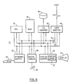
- FIG. 6 is a schematic block diagram of a personal computer on which the present invention may be implemented.
- the personal computer comprises a number of different system units connected via a system bus 72.
- the system bus comprises a data bus 74, an address bus 76 and a control bus 78.
- Connected to the system bus is a microprocessor 70, random access memory 80, a keyboard adapter 88, a display adapter 92 and an I/O adapter 82.
- the keyboard adapter is used to connect a keyboard 90 to the system bus.
- the display adapter includes a display buffer 22 for storing information defining a screen of data for display and connects the system bus to a display device 94 such as a cathode ray tube (CRT) device.
- CTR cathode ray tube
- the I/O adapter likewise provides a connection between other input/output devices 84 (eg. DASDs) and the system bus.
- the personal computer may also be provided, as is shown, with a communications adapter 86 for allowing the personal computer to be connected to and to communicate with an external processor or processors such as a host processor (not shown).
- a display system in accordance with the invention can be implemented on the personal computer by suitably programming.
- the logic described above can be provided by appropriate programming code and the range storage registers can be provided by suitably configuring the system memory (RAM 80).
- the personal computer is used to implement a display system in accordance with the invention, then the hardware illustrated above will normally suffice. This is also the case if the personal computer is used to analyse waveforms which have already been sampled and digitised.
- the personal computer can, however, be conf igured as a waveform analyser and additionally comprise a microphone 98 and digital sampler 96 for sampling the speech directly.
- the present invention is not, however, limited to such an implementation and may be implemented as a special purpose processor or as a special purpose adapter for use with a general purpose computer.
- one or more of the storage elements mentioned could be provided by units of discrete storage.
- the logic may well be provided wholly or in part by special purpose logic.
- the invention has been particularly des strictlycribed with reference to the use of a visual display device such as a cathode ray tube
- the invention also covers the use of other forms of display devices such as, for example, a pen plotter.
- a pen plotter for example, not only is time saved due to overplotting being avoided but also pen wear is reduced.
- the invention is particularly described with reference to the display of a data array in the form of a speech waveform, the invention is also applicable to, and is intended to cover, the display of other arrays of data.
Landscapes
- Engineering & Computer Science (AREA)
- Radar, Positioning & Navigation (AREA)
- Remote Sensing (AREA)
- Physics & Mathematics (AREA)
- Computer Hardware Design (AREA)
- General Physics & Mathematics (AREA)
- Theoretical Computer Science (AREA)
- Controls And Circuits For Display Device (AREA)
- Digital Computer Display Output (AREA)
Applications Claiming Priority (2)
| Application Number | Priority Date | Filing Date | Title |
|---|---|---|---|
| GB8820013A GB2222285A (en) | 1988-08-23 | 1988-08-23 | Display system |
| GB8820013 | 1988-08-23 |
Publications (2)
| Publication Number | Publication Date |
|---|---|
| EP0356053A2 true EP0356053A2 (fr) | 1990-02-28 |
| EP0356053A3 EP0356053A3 (fr) | 1990-07-25 |
Family
ID=10642581
Family Applications (1)
| Application Number | Title | Priority Date | Filing Date |
|---|---|---|---|
| EP89307978A Withdrawn EP0356053A3 (fr) | 1988-08-23 | 1989-08-04 | Système de visualisation |
Country Status (4)
| Country | Link |
|---|---|
| US (1) | US5079720A (fr) |
| EP (1) | EP0356053A3 (fr) |
| JP (1) | JPH0269818A (fr) |
| GB (1) | GB2222285A (fr) |
Cited By (1)
| Publication number | Priority date | Publication date | Assignee | Title |
|---|---|---|---|---|
| EP0780824A1 (fr) * | 1995-12-20 | 1997-06-25 | International Business Machines Corporation | Procédé et système pour la présentation visuelle de données audio |
Families Citing this family (6)
| Publication number | Priority date | Publication date | Assignee | Title |
|---|---|---|---|---|
| US5485078A (en) * | 1994-03-23 | 1996-01-16 | Venturedyne, Ltd. | Method for analyzing a circuit board waveform for faults |
| US6025826A (en) * | 1997-06-30 | 2000-02-15 | Sun Microsystems, Inc. | Method and apparatus for handling alpha premultiplication of image data |
| NL1007124C2 (nl) * | 1997-09-26 | 1999-03-29 | Sat Investment Consultancy B V | Systeem voor het bepalen en weergeven van het verloop van ten minste één variabele. |
| US6751565B2 (en) * | 2002-06-21 | 2004-06-15 | Springsoft, Inc. | Fast waveform display method and system |
| US7610553B1 (en) * | 2003-04-05 | 2009-10-27 | Apple Inc. | Method and apparatus for reducing data events that represent a user's interaction with a control interface |
| US20190171927A1 (en) * | 2017-12-06 | 2019-06-06 | Facebook, Inc. | Layer-level quantization in neural networks |
Family Cites Families (6)
| Publication number | Priority date | Publication date | Assignee | Title |
|---|---|---|---|---|
| US3576948A (en) * | 1968-06-10 | 1971-05-04 | Honeywell Inc | System for recording high frequency signals on a recorder having a lower frequency response |
| US4030119A (en) * | 1975-10-01 | 1977-06-14 | General Electric Company | Video window control |
| FR2381313A2 (fr) * | 1975-12-31 | 1978-09-15 | Labo Electronique Physique | Enregistrement et visualisation de signaux |
| US4509530A (en) * | 1983-12-27 | 1985-04-09 | International Business Machines Corporation | System for plotting a miniature ECG |
| US4755960A (en) * | 1985-06-20 | 1988-07-05 | Tektronix, Inc. | Waveform data compressing circuit |
| US4713771A (en) * | 1985-10-28 | 1987-12-15 | Tektronix, Inc. | Digital minimum-maximum value sequence processor |
-
1988
- 1988-08-23 GB GB8820013A patent/GB2222285A/en not_active Withdrawn
-
1989
- 1989-02-14 US US07/310,808 patent/US5079720A/en not_active Expired - Fee Related
- 1989-06-19 JP JP1154814A patent/JPH0269818A/ja active Pending
- 1989-08-04 EP EP89307978A patent/EP0356053A3/fr not_active Withdrawn
Cited By (1)
| Publication number | Priority date | Publication date | Assignee | Title |
|---|---|---|---|---|
| EP0780824A1 (fr) * | 1995-12-20 | 1997-06-25 | International Business Machines Corporation | Procédé et système pour la présentation visuelle de données audio |
Also Published As
| Publication number | Publication date |
|---|---|
| US5079720A (en) | 1992-01-07 |
| GB2222285A (en) | 1990-02-28 |
| EP0356053A3 (fr) | 1990-07-25 |
| JPH0269818A (ja) | 1990-03-08 |
| GB8820013D0 (en) | 1988-09-21 |
Similar Documents
| Publication | Publication Date | Title |
|---|---|---|
| US5883634A (en) | System and method for clipping pixels drawn in one of a plurality of windows in a computer graphics system | |
| US4958378A (en) | Method and apparatus for detecting changes in raster data | |
| US7305130B2 (en) | Method and system for data entry of handwritten symbols | |
| EP0112942B1 (fr) | Système et méthode d'affichage de graphiques | |
| US4496944A (en) | Graphics display system and method including associative addressing | |
| US4492956A (en) | Graphics display system and method including preclipping circuit | |
| US4764885A (en) | Minimum parallax stylus detection subsystem for a display device | |
| US5926567A (en) | Method and apparatus for storing and rapidly displaying graphic data | |
| US4538144A (en) | Graphic display device having graphic generator for shading graphs | |
| US5911013A (en) | Character recognition method and apparatus capable of handling handwriting | |
| EP0356053A2 (fr) | Système de visualisation | |
| US4394650A (en) | Graphic and data character video display system | |
| US4918429A (en) | Display system with symbol font memory | |
| US5202671A (en) | Pick function implementation in a parallel processing system | |
| US5068803A (en) | Method and apparatus for filling contours in digital typefaces | |
| US6344856B1 (en) | Text optimization | |
| EP0425178A2 (fr) | Système d'affichage graphique | |
| US4398190A (en) | Character generator display system | |
| GB2266823A (en) | Correlation of cursor position in a computer system | |
| US4384285A (en) | Data character video display system with visual attributes | |
| US5452409A (en) | System and method for creating and modifying graphs in a computer system using a multiple segment graph format | |
| US5644691A (en) | Method and apparatus for accelerated filling of polygons on a computer display by rectangular decomposition | |
| US6304270B1 (en) | Method and apparatus for determining simple convex polygons | |
| US6064405A (en) | Method and apparatus for a cached video hardware cursor | |
| JPH0782530B2 (ja) | 手書き文字認識装置 |
Legal Events
| Date | Code | Title | Description |
|---|---|---|---|
| PUAI | Public reference made under article 153(3) epc to a published international application that has entered the european phase |
Free format text: ORIGINAL CODE: 0009012 |
|
| AK | Designated contracting states |
Kind code of ref document: A2 Designated state(s): DE FR GB |
|
| PUAL | Search report despatched |
Free format text: ORIGINAL CODE: 0009013 |
|
| AK | Designated contracting states |
Kind code of ref document: A3 Designated state(s): DE FR GB |
|
| 17P | Request for examination filed |
Effective date: 19900621 |
|
| 17Q | First examination report despatched |
Effective date: 19920515 |
|
| STAA | Information on the status of an ep patent application or granted ep patent |
Free format text: STATUS: THE APPLICATION IS DEEMED TO BE WITHDRAWN |
|
| 18D | Application deemed to be withdrawn |
Effective date: 19930427 |