EP0356057A1 - Réducteur de bruit - Google Patents
Réducteur de bruit Download PDFInfo
- Publication number
- EP0356057A1 EP0356057A1 EP89308000A EP89308000A EP0356057A1 EP 0356057 A1 EP0356057 A1 EP 0356057A1 EP 89308000 A EP89308000 A EP 89308000A EP 89308000 A EP89308000 A EP 89308000A EP 0356057 A1 EP0356057 A1 EP 0356057A1
- Authority
- EP
- European Patent Office
- Prior art keywords
- insert
- flow
- passage
- valve
- flow channel
- Prior art date
- Legal status (The legal status is an assumption and is not a legal conclusion. Google has not performed a legal analysis and makes no representation as to the accuracy of the status listed.)
- Granted
Links
- 239000007788 liquid Substances 0.000 claims description 7
- 238000011144 upstream manufacturing Methods 0.000 claims description 5
- 239000000463 material Substances 0.000 claims description 3
- 230000001105 regulatory effect Effects 0.000 claims description 3
- 230000004888 barrier function Effects 0.000 claims description 2
- 230000002093 peripheral effect Effects 0.000 claims description 2
- 230000000694 effects Effects 0.000 claims 1
- 230000030279 gene silencing Effects 0.000 claims 1
- 239000003381 stabilizer Substances 0.000 abstract description 3
- 238000007789 sealing Methods 0.000 abstract 1
- 230000001743 silencing effect Effects 0.000 abstract 1
- 239000012530 fluid Substances 0.000 description 14
- XLYOFNOQVPJJNP-UHFFFAOYSA-N water Substances O XLYOFNOQVPJJNP-UHFFFAOYSA-N 0.000 description 8
- 230000009467 reduction Effects 0.000 description 6
- 230000009471 action Effects 0.000 description 4
- 230000004044 response Effects 0.000 description 4
- 230000008901 benefit Effects 0.000 description 3
- 230000015572 biosynthetic process Effects 0.000 description 3
- 238000005755 formation reaction Methods 0.000 description 3
- 238000013016 damping Methods 0.000 description 2
- 230000005484 gravity Effects 0.000 description 2
- 230000003584 silencer Effects 0.000 description 2
- 238000005406 washing Methods 0.000 description 2
- 230000004323 axial length Effects 0.000 description 1
- 230000033228 biological regulation Effects 0.000 description 1
- 230000006835 compression Effects 0.000 description 1
- 238000007906 compression Methods 0.000 description 1
- 230000002517 constrictor effect Effects 0.000 description 1
- 230000007423 decrease Effects 0.000 description 1
- 230000001419 dependent effect Effects 0.000 description 1
- 230000037431 insertion Effects 0.000 description 1
- 238000003780 insertion Methods 0.000 description 1
- 230000007246 mechanism Effects 0.000 description 1
- 239000004033 plastic Substances 0.000 description 1
- 229920003023 plastic Polymers 0.000 description 1
- 230000000750 progressive effect Effects 0.000 description 1
Images

Classifications
-
- F—MECHANICAL ENGINEERING; LIGHTING; HEATING; WEAPONS; BLASTING
- F16—ENGINEERING ELEMENTS AND UNITS; GENERAL MEASURES FOR PRODUCING AND MAINTAINING EFFECTIVE FUNCTIONING OF MACHINES OR INSTALLATIONS; THERMAL INSULATION IN GENERAL
- F16K—VALVES; TAPS; COCKS; ACTUATING-FLOATS; DEVICES FOR VENTING OR AERATING
- F16K47/00—Means in valves for absorbing fluid energy
- F16K47/02—Means in valves for absorbing fluid energy for preventing water-hammer or noise
-
- F—MECHANICAL ENGINEERING; LIGHTING; HEATING; WEAPONS; BLASTING
- F16—ENGINEERING ELEMENTS AND UNITS; GENERAL MEASURES FOR PRODUCING AND MAINTAINING EFFECTIVE FUNCTIONING OF MACHINES OR INSTALLATIONS; THERMAL INSULATION IN GENERAL
- F16K—VALVES; TAPS; COCKS; ACTUATING-FLOATS; DEVICES FOR VENTING OR AERATING
- F16K31/00—Actuating devices; Operating means; Releasing devices
- F16K31/12—Actuating devices; Operating means; Releasing devices actuated by fluid
- F16K31/36—Actuating devices; Operating means; Releasing devices actuated by fluid in which fluid from the circuit is constantly supplied to the fluid motor
- F16K31/40—Actuating devices; Operating means; Releasing devices actuated by fluid in which fluid from the circuit is constantly supplied to the fluid motor with electrically-actuated member in the discharge of the motor
- F16K31/402—Actuating devices; Operating means; Releasing devices actuated by fluid in which fluid from the circuit is constantly supplied to the fluid motor with electrically-actuated member in the discharge of the motor acting on a diaphragm
- F16K31/404—Actuating devices; Operating means; Releasing devices actuated by fluid in which fluid from the circuit is constantly supplied to the fluid motor with electrically-actuated member in the discharge of the motor acting on a diaphragm the discharge being effected through the diaphragm and being blockable by an electrically-actuated member making contact with the diaphragm
-
- F—MECHANICAL ENGINEERING; LIGHTING; HEATING; WEAPONS; BLASTING
- F16—ENGINEERING ELEMENTS AND UNITS; GENERAL MEASURES FOR PRODUCING AND MAINTAINING EFFECTIVE FUNCTIONING OF MACHINES OR INSTALLATIONS; THERMAL INSULATION IN GENERAL
- F16L—PIPES; JOINTS OR FITTINGS FOR PIPES; SUPPORTS FOR PIPES, CABLES OR PROTECTIVE TUBING; MEANS FOR THERMAL INSULATION IN GENERAL
- F16L55/00—Devices or appurtenances for use in, or in connection with, pipes or pipe systems
- F16L55/02—Energy absorbers; Noise absorbers
- F16L55/027—Throttle passages
Definitions
- This invention relates to a combination comprising a fluid valve having an upstream flow regulator, especially in its input conduit.
- a fluid valve having an upstream flow regulator especially in its input conduit.
- the presence of the flow regulator generates unpleasant noise in the regulated fluid flow.
- noise is reduced by having a passageway of somewhat restricted cross-section before the valve, but downstream of the flow regulator, such that (1) a chamber of intermediate pressure is created, and such that (2) there is, at least at some input fluid pressures, a diminution in the velocity of the fluid leaving the valve passageway.
- the passageway cross-section cannot be unduly restricted, perhaps because the intermediate pressure zone or chamber will be at too high a pressure.
- the restriction is provided by means of an insert in the valve conduit itself, preferably of synthetic plastics material.
- the insert may also provide an orifice which decreases in response to increased pressures.
- a venturi cone-shaped tapered-down formation or insert tends in fact to be less effective than a shape (e.g. that of Fig. 3) which allows a greater volume of the intermediate pressure chamber, perhaps because fluid remains longer in the chamber.
- a preferred shape tends to reflect the flow back, and to constrain or trap the liquid in the intermediate chamber (20) from readily entering the flow out of the intermediate chamber, in that a re-entrant blind channel (26) is provided.
- the constraint then may be a central boss portion 25 on a transverse (therefore reflecting) wall section 26A of the insert, the boss portion having a tubular bore passage (24), which constitutes the flow outlet of the intermediate chamber.
- GB-A-2 147 431 proposes inserts in order to quieten liquid noise originating either from a thermostatically controlled valve, or upstream of it.
- the inserts proposed in this reference each have a restricted passage, but it tends to be very long and the teaching is, indeed, based on its length; such length preventing in all embodiments the provision of the progressive geometrical changes constituting one of the more important fundamentals of the present invention.
- inserts of this reference may help the problem described, but would certainly not be satisfactory for the high noise levels generated when the input pressures are very high, because then the aperture(s) of pressure-responsive flow regulators become compensatingly small, and the actual abruptness of the drop in pressure correspondingly high, introducing turbulence and cavitation.
- the fluid pressure drop for very high applied pressures may be disproportionate at the flow regulator stage.
- the benefits of the invention are more fully realised, according to an option, when the noise-reducing insert also responds in shape, and so the size of the restricted aperture becomes smaller in response to the pressure (by use of appropriate materials and contouring of the immediate surrounds of the restricted aperture, to give it a variable constrictive effect).
- the extra pressure drops, engendered by response of the flow regulator, are then proportioned between it and the said restricted passageway.
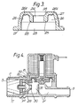
- a two-port valve 1 has a body 2 providing an input port 3, an input conduit 4, an output port 5, a valve seat 6 and a valve flap 7 which can be lowered from the position shown, to obstruct seat 6. When unobstructed, seat 6 permits fluid flow between ports 3 and 5 via input conduit 4.
- the valve flap 7 may be raised electromagnetically by the action of a solenoid coil 8 on an armature 9 coupled to the flap. Lowering the flap to a closing position would be by allowing the armature 9 to fall by gravity and/or pressure of a compression spring 10.
- this action is of the well-known indirect type, in that the flap is attached to a diaphragm 11 which seals off a pilot chamber 12 above it, except that there is a small bleed hole 13 eccentrically, and a slightly less small pilot hole 14 centrally, in the diaphragm.
- the diaphragm is clamped around its periphery 15 and has an annular thinner flexible portion 16 to allow easy raising and lowering of the flap 7 which it carries.
- pilot action is well-known, i.e. when armature 9 and flap 7 are down, pilot hole 14 is obstructed, closure being assisted by the action of the spring 10.
- the spring need not be very strong because water forces are nearly balanced on the diaphragm. The closed position is stable, and valve seat 6 is likewise blocked.
- pilot hole 14 is unblocked, and there is net water flow out of pilot chamber 12 because bleed hole 13 cannot replenish the chamber. Water forces urge the diaphragm upwards, seat 6 is unblocked, and water flows from input port 3 to output port 5.
- a rigid round tray-shaped insert 15A may provide (a) stiffening, (b) the valve flap 7, and (c) a raised annulus 16 to limit the raising of the flap and reclosure of hole 14 against the armature.
- Such mechanisms especially, in combination with an input flow regulator 17 in input conduit 4 can, as aforesaid, create undesirable noise.
- a possible reason for the often excessive noise is the distortion that takes place in regulator 17 when input pressure is high, which mechanically constricts the flow to bring about its regulation function.
- the invention proposes removal or reduction of such noise by a restricted passageway e.g. by the insert 18 of Fig 2 or 3 or the insert 19 of Fig 4, or by similar formations of the conduit downstream of the flow regulator 17.
- the restriction should be preferably, for the best noise damping, spaced or extensive somewhat downstream from the noise regulator, to provide an intermediate chamber 20 of pressure P ⁇ , intermediate the pressures P at the input Port 3 and P′ at the output port 5.
- the insert 18 may have a peripheral flange 21 to hold it in place, a cylindrical axial passage 23 somewhat smaller in diameter than the exit passage 22 of the flow regulator 17, a yet smaller cylindrical axial passage 24 downstream of passage 23 and provided through a boss portion 25.
- the boss portion also forms an annular re-entrant blind channel 26 around the boss, which traps fluid and is believed to assist the sound-deadening.
- Blind channel 26 also enables the intermediate chamber 20 to have a somewhat larger volume than the venturi cone below. Probably the larger the volume, the better the noise reduction, up to some limit.
- the insert 18 of Fig 2 may alternatively have the initial shape shown in Fig 3, in which the exterior portion 27 is tapered down somewhat in the downstream direction; the internal boss part 28 of boss 25 may be flared towards the downstream.
- FIG. 4 An alternative insert 19 is shown in Fig 4, in which the intermediate chamber 29 at intermediate pressure P ⁇ , is now arranged to have a conical shape, rather than the cylinder 23 and re-entrant chamber 26 shape exhibited in Figs 2 and 3.
- the cone shape can follow well-known venturi-cone principles, in order to promote streamline, or less turbulent and therefore quieter flows on the inlet side of the valve.
- the cone shape provides progressively reducing cross-sections, somewhat smaller than that of the flow regulator, tapering to the diameter of restricted section 30.
- the intermediate chamber may provide a venturi cone as in Fig 4, although surprisingly, it is usually found more effective for the chamber to be cylindrical as in Figs 2 and 3, whereby it is as large in volume as permitted by a given axial length, consistent with forming the grading-down in successive cross-sections.
- This successive grading-down promotes the noise-damping or deadening of the invention, where such noise has been created at least in part by a flow regulator, particularly when followed by a main ON-OFF valve seat whose cross-section is generally axial of the fluid flow, thus involving multiple changes in direction of the main flow, e.g. round an effective barrier 31 (see Figs 1, 2 and 4).
- This pilot valve arrangement appears to derive particular benefit from the noise-reducing restricted passageway means of the invention.
- a wall or flange 32 may project vertically downwards from the body 2 and then curl inwardly horizontally at 33 to assist the clamping of the periphery 15 of the diaphragm.
- the vertical portion can be used to hold the periphery of either insert 18 (Fig 2) or 19, e.g. pressed against the flow regulator 17.
- the silencer restrictive aperture 24 or 30 should be as small as possible. However, it should be large enough for passage of the standard or stablised flow rate at the lowest pressures likely to be encountered. In practice, a compromise may have to be reached, to cater for the highest and lowest likely incoming water pressures.
- the pressure-sensitive silencer mentioned above can be adopted, in which the aperture 24 or 30 would become larger or smaller in response to mains pressure changes, in unison with changes in the effective aperture of the flow stabiliser element 17.
- the invention can provide a fluid valve comprising a wall (31) which, when the valve is controlled open forms a partial obstacle across fluid flow between an input port (3) and an output port (5), a distortable flow regulator (17), also impeding the flow adjacent the input port, and a noise-reducing restricted passageway portion (18 or 19) located downstream of the flow regulator and upstream of the wall obstacle (31).
- This wall may be part of the support for the valve seat, e.g. a pilot valve seat.
- a further wall (32) may provide both a clamping face for the periphery of the insert (18 or 19) and a clamping surface (33) for the diaphragm periphery (15).
Landscapes
- Engineering & Computer Science (AREA)
- General Engineering & Computer Science (AREA)
- Mechanical Engineering (AREA)
- Details Of Valves (AREA)
- Safety Valves (AREA)
- Magnetically Actuated Valves (AREA)
- Lift Valve (AREA)
Applications Claiming Priority (2)
| Application Number | Priority Date | Filing Date | Title |
|---|---|---|---|
| GB888819838A GB8819838D0 (en) | 1988-08-20 | 1988-08-20 | Noise limiter |
| GB8819838 | 1988-08-20 |
Publications (2)
| Publication Number | Publication Date |
|---|---|
| EP0356057A1 true EP0356057A1 (fr) | 1990-02-28 |
| EP0356057B1 EP0356057B1 (fr) | 1992-12-02 |
Family
ID=10642476
Family Applications (1)
| Application Number | Title | Priority Date | Filing Date |
|---|---|---|---|
| EP19890308000 Expired EP0356057B1 (fr) | 1988-08-20 | 1989-08-07 | Réducteur de bruit |
Country Status (4)
| Country | Link |
|---|---|
| EP (1) | EP0356057B1 (fr) |
| DE (1) | DE68903703T2 (fr) |
| ES (1) | ES2036034T3 (fr) |
| GB (1) | GB8819838D0 (fr) |
Cited By (4)
| Publication number | Priority date | Publication date | Assignee | Title |
|---|---|---|---|---|
| DE4444773A1 (de) * | 1994-12-16 | 1996-06-27 | Ford Werke Ag | Hülseneinsatz mit Drosselbohrung für ein eine Flüssigkeit enthaltendes Gehäuse |
| GB2298935A (en) * | 1992-08-13 | 1996-09-18 | Aztec Dev Ltd | Fluid flow control valve |
| US5716038A (en) * | 1992-08-13 | 1998-02-10 | Aztec Developments Limited | Proportional flow control valve |
| WO2003054436A1 (fr) * | 2001-12-21 | 2003-07-03 | Eltek S.P.A. | Dispositif permettant de reguler l'ecoulement d'un fluide, notamment pour les electrovannes |
Citations (4)
| Publication number | Priority date | Publication date | Assignee | Title |
|---|---|---|---|---|
| DE1267482B (de) * | 1965-01-21 | 1968-05-02 | Danfoss As | Drosseleinrichtung zum Konstanthalten der Durchflussmenge durch eine Rohrleitung |
| US3480040A (en) * | 1965-10-20 | 1969-11-25 | Dole Valve Co | Single-inlet,double outlet valve |
| FR2295330A1 (fr) * | 1974-12-18 | 1976-07-16 | Deles Louis | Electro-vanne perfectionnee pour appareils menagers |
| FR2552849A1 (fr) * | 1983-10-01 | 1985-04-05 | Danfoss As | Soupape de radiateur chauffant |
-
1988
- 1988-08-20 GB GB888819838A patent/GB8819838D0/en active Pending
-
1989
- 1989-08-07 DE DE1989603703 patent/DE68903703T2/de not_active Expired - Fee Related
- 1989-08-07 ES ES89308000T patent/ES2036034T3/es not_active Expired - Lifetime
- 1989-08-07 EP EP19890308000 patent/EP0356057B1/fr not_active Expired
Patent Citations (4)
| Publication number | Priority date | Publication date | Assignee | Title |
|---|---|---|---|---|
| DE1267482B (de) * | 1965-01-21 | 1968-05-02 | Danfoss As | Drosseleinrichtung zum Konstanthalten der Durchflussmenge durch eine Rohrleitung |
| US3480040A (en) * | 1965-10-20 | 1969-11-25 | Dole Valve Co | Single-inlet,double outlet valve |
| FR2295330A1 (fr) * | 1974-12-18 | 1976-07-16 | Deles Louis | Electro-vanne perfectionnee pour appareils menagers |
| FR2552849A1 (fr) * | 1983-10-01 | 1985-04-05 | Danfoss As | Soupape de radiateur chauffant |
Non-Patent Citations (1)
| Title |
|---|
| PATENT ABSTRACTS OF JAPAN, vol. 7, no. 183 (M-235)[1328], 12th August 1983; & JP-A-58 84 275 (MATSUSHITA DENKI SANGYO K.K.) 20-05-1983 * |
Cited By (7)
| Publication number | Priority date | Publication date | Assignee | Title |
|---|---|---|---|---|
| GB2298935A (en) * | 1992-08-13 | 1996-09-18 | Aztec Dev Ltd | Fluid flow control valve |
| GB2298935B (en) * | 1992-08-13 | 1997-03-26 | Aztec Dev Ltd | Improvements in or relating to the dispensing of fluids |
| US5716038A (en) * | 1992-08-13 | 1998-02-10 | Aztec Developments Limited | Proportional flow control valve |
| US5841027A (en) * | 1992-08-13 | 1998-11-24 | Aztec Development Ltd | Piezoelectric flow transducer |
| DE4444773A1 (de) * | 1994-12-16 | 1996-06-27 | Ford Werke Ag | Hülseneinsatz mit Drosselbohrung für ein eine Flüssigkeit enthaltendes Gehäuse |
| WO2003054436A1 (fr) * | 2001-12-21 | 2003-07-03 | Eltek S.P.A. | Dispositif permettant de reguler l'ecoulement d'un fluide, notamment pour les electrovannes |
| US7143992B2 (en) | 2001-12-21 | 2006-12-05 | Eltek S.P.A. | Device for regulating the flow of a fluid, in particular for solenoid valves |
Also Published As
| Publication number | Publication date |
|---|---|
| EP0356057B1 (fr) | 1992-12-02 |
| DE68903703D1 (de) | 1993-01-14 |
| GB8819838D0 (en) | 1988-09-21 |
| ES2036034T3 (es) | 1993-05-01 |
| DE68903703T2 (de) | 1993-04-01 |
Similar Documents
| Publication | Publication Date | Title |
|---|---|---|
| CN101548250B (zh) | 流量调节器 | |
| CN100516606C (zh) | 抗气蚀阀组件 | |
| US5765814A (en) | Flow rate stabilizer for throttling valves | |
| US4206901A (en) | Pressure-actuated valve with metering choke | |
| US3695290A (en) | Noise suppressing device for fluid flow lines | |
| WO2012066487A1 (fr) | Soupape d'évacuation d'air | |
| US5337789A (en) | Vortex valves | |
| US3592223A (en) | Pilot-operated modulating valve system and flow stabilizer incorporated therein | |
| EP0356057B1 (fr) | Réducteur de bruit | |
| KR102189454B1 (ko) | 조절 가능한 디스크 가이드 구조를 가지는 캐비테이션 및 맥동 완화 감압 컨트롤밸브 | |
| MXPA97008144A (en) | Apparatus to delete the noise generated by a water flow through a valve of a | |
| AU616359B2 (en) | Low noise tank valve | |
| EP0473264B1 (fr) | Soupape à cartouche pour régler la pression de gaz | |
| US20210389785A1 (en) | Pressure reducing valve with an integral venturi | |
| KR100721683B1 (ko) | 조리개식 가변밸브 | |
| CN112741972A (zh) | 一种比例混合器 | |
| US3391900A (en) | Diaphragm flow control device | |
| JPS6131263Y2 (fr) | ||
| JP2573718Y2 (ja) | 逆止弁 | |
| JP3341198B2 (ja) | パイロット式背圧弁 | |
| USRE21597E (en) | Service regulator | |
| JPH01261583A (ja) | 給水弁 | |
| JPH01193483A (ja) | 電磁弁 | |
| JPS595192B2 (ja) | 貯水槽用ボ−ルタツプ | |
| JP3392449B2 (ja) | パイロット形電磁弁 |
Legal Events
| Date | Code | Title | Description |
|---|---|---|---|
| PUAI | Public reference made under article 153(3) epc to a published international application that has entered the european phase |
Free format text: ORIGINAL CODE: 0009012 |
|
| AK | Designated contracting states |
Kind code of ref document: A1 Designated state(s): DE ES FR GB IT |
|
| 17P | Request for examination filed |
Effective date: 19900622 |
|
| 17Q | First examination report despatched |
Effective date: 19910515 |
|
| GRAA | (expected) grant |
Free format text: ORIGINAL CODE: 0009210 |
|
| AK | Designated contracting states |
Kind code of ref document: B1 Designated state(s): DE ES FR GB IT |
|
| ITF | It: translation for a ep patent filed | ||
| REF | Corresponds to: |
Ref document number: 68903703 Country of ref document: DE Date of ref document: 19930114 |
|
| ET | Fr: translation filed | ||
| REG | Reference to a national code |
Ref country code: ES Ref legal event code: FG2A Ref document number: 2036034 Country of ref document: ES Kind code of ref document: T3 |
|
| PLBE | No opposition filed within time limit |
Free format text: ORIGINAL CODE: 0009261 |
|
| STAA | Information on the status of an ep patent application or granted ep patent |
Free format text: STATUS: NO OPPOSITION FILED WITHIN TIME LIMIT |
|
| 26N | No opposition filed | ||
| PGFP | Annual fee paid to national office [announced via postgrant information from national office to epo] |
Ref country code: GB Payment date: 19980702 Year of fee payment: 10 |
|
| PGFP | Annual fee paid to national office [announced via postgrant information from national office to epo] |
Ref country code: FR Payment date: 19980727 Year of fee payment: 10 |
|
| PGFP | Annual fee paid to national office [announced via postgrant information from national office to epo] |
Ref country code: ES Payment date: 19980805 Year of fee payment: 10 |
|
| PGFP | Annual fee paid to national office [announced via postgrant information from national office to epo] |
Ref country code: DE Payment date: 19980827 Year of fee payment: 10 |
|
| PG25 | Lapsed in a contracting state [announced via postgrant information from national office to epo] |
Ref country code: GB Free format text: LAPSE BECAUSE OF NON-PAYMENT OF DUE FEES Effective date: 19990807 |
|
| PG25 | Lapsed in a contracting state [announced via postgrant information from national office to epo] |
Ref country code: ES Free format text: LAPSE BECAUSE OF NON-PAYMENT OF DUE FEES Effective date: 19990808 |
|
| GBPC | Gb: european patent ceased through non-payment of renewal fee |
Effective date: 19990807 |
|
| PG25 | Lapsed in a contracting state [announced via postgrant information from national office to epo] |
Ref country code: FR Free format text: LAPSE BECAUSE OF NON-PAYMENT OF DUE FEES Effective date: 20000428 |
|
| PG25 | Lapsed in a contracting state [announced via postgrant information from national office to epo] |
Ref country code: DE Free format text: LAPSE BECAUSE OF NON-PAYMENT OF DUE FEES Effective date: 20000601 |
|
| REG | Reference to a national code |
Ref country code: FR Ref legal event code: ST |
|
| REG | Reference to a national code |
Ref country code: ES Ref legal event code: FD2A Effective date: 20000911 |
|
| PG25 | Lapsed in a contracting state [announced via postgrant information from national office to epo] |
Ref country code: IT Free format text: LAPSE BECAUSE OF NON-PAYMENT OF DUE FEES;WARNING: LAPSES OF ITALIAN PATENTS WITH EFFECTIVE DATE BEFORE 2007 MAY HAVE OCCURRED AT ANY TIME BEFORE 2007. THE CORRECT EFFECTIVE DATE MAY BE DIFFERENT FROM THE ONE RECORDED. Effective date: 20050807 |