EP0356310B1 - Elektronischer Starter eines Motors - Google Patents
Elektronischer Starter eines Motors Download PDFInfo
- Publication number
- EP0356310B1 EP0356310B1 EP89402269A EP89402269A EP0356310B1 EP 0356310 B1 EP0356310 B1 EP 0356310B1 EP 89402269 A EP89402269 A EP 89402269A EP 89402269 A EP89402269 A EP 89402269A EP 0356310 B1 EP0356310 B1 EP 0356310B1
- Authority
- EP
- European Patent Office
- Prior art keywords
- terminal
- resistor
- gate
- output
- nand gate
- Prior art date
- Legal status (The legal status is an assumption and is not a legal conclusion. Google has not performed a legal analysis and makes no representation as to the accuracy of the status listed.)
- Expired - Lifetime
Links
- 239000007858 starting material Substances 0.000 title claims description 24
- 238000004804 winding Methods 0.000 claims description 68
- 239000003990 capacitor Substances 0.000 claims description 44
- 230000006698 induction Effects 0.000 claims description 10
- 238000001514 detection method Methods 0.000 description 5
- 230000008878 coupling Effects 0.000 description 2
- 238000010168 coupling process Methods 0.000 description 2
- 238000005859 coupling reaction Methods 0.000 description 2
- 230000007423 decrease Effects 0.000 description 2
- 230000001360 synchronised effect Effects 0.000 description 2
- 230000003213 activating effect Effects 0.000 description 1
- 230000002411 adverse Effects 0.000 description 1
- 230000000694 effects Effects 0.000 description 1
- 230000004907 flux Effects 0.000 description 1
- 238000004519 manufacturing process Methods 0.000 description 1
- 238000000034 method Methods 0.000 description 1
- 230000000087 stabilizing effect Effects 0.000 description 1
- 230000001960 triggered effect Effects 0.000 description 1
Images


Classifications
-
- H—ELECTRICITY
- H02—GENERATION; CONVERSION OR DISTRIBUTION OF ELECTRIC POWER
- H02P—CONTROL OR REGULATION OF ELECTRIC MOTORS, ELECTRIC GENERATORS OR DYNAMO-ELECTRIC CONVERTERS; CONTROLLING TRANSFORMERS, REACTORS OR CHOKE COILS
- H02P1/00—Arrangements for starting electric motors or dynamo-electric converters
-
- H—ELECTRICITY
- H02—GENERATION; CONVERSION OR DISTRIBUTION OF ELECTRIC POWER
- H02P—CONTROL OR REGULATION OF ELECTRIC MOTORS, ELECTRIC GENERATORS OR DYNAMO-ELECTRIC CONVERTERS; CONTROLLING TRANSFORMERS, REACTORS OR CHOKE COILS
- H02P1/00—Arrangements for starting electric motors or dynamo-electric converters
- H02P1/16—Arrangements for starting electric motors or dynamo-electric converters for starting dynamo-electric motors or dynamo-electric converters
- H02P1/42—Arrangements for starting electric motors or dynamo-electric converters for starting dynamo-electric motors or dynamo-electric converters for starting an individual single-phase induction motor
- H02P1/44—Arrangements for starting electric motors or dynamo-electric converters for starting dynamo-electric motors or dynamo-electric converters for starting an individual single-phase induction motor by phase-splitting with a capacitor
-
- H—ELECTRICITY
- H02—GENERATION; CONVERSION OR DISTRIBUTION OF ELECTRIC POWER
- H02H—EMERGENCY PROTECTIVE CIRCUIT ARRANGEMENTS
- H02H9/00—Emergency protective circuit arrangements for limiting excess current or voltage without disconnection
Definitions
- This invention relates to electronic motor starters for starting single-phase induction motors, which can replace conventional centrifugal switches, mechanical voltage relays and current type starting relays.
- U.S. Patent N o 4,605,888, issued August 12, 1986 discloses an electronic motor starter for use with a single-phase induction motor having a starting winding (L2) comprising : a triac (S1) having a first terminal (T1) for connection to a terminal of a motor power source, a second terminal (T2) for connection to the starting winding and a gate terminal (G); a detecting means for detecting the voltage across the starting winding having a diode (D2), two resistors (R5 and R2) and a capacitor (C2); a hysteresis means (R3, R4, C3, TR2) responsive to the voltage across the starting winding as detected across the capacitor (C2) and having a hysteresis characteristic; and a trigger means including a transistor (TR1) whose base is connected to the output of the hysteresis means, a thyristor (S2) and a diode bridge (D1) having first and second AC terminals and first and second DC terminal
- the electronic starter of U.S. Patent N o 4,605,888 has a drawback in that a time constant must be adjusted as the amplifying degree and the avalanche voltage of a transistor in the hysteresis means vary for each production lot of the transistors.
- the starter also has the disadvantage that it cannot maintain a steady motor starting function where the line voltage variation is great, making the voltage compensation impossible because the relay has only about a 30 volts hysteresis width.
- the motor starters produce no arc and are semi-permanent.
- Fig. 1 shows a preferred embodiment of the electronic motor starter according to the present invention.
- Fig. 2 shows another embodiment of the invention using NOT gates.
- Fig. 3 shows another embodiment or the present invention using NAND gates and a photocoupler.
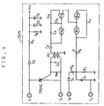
- Fig. 4 shows a further embodiment of the present invention.
- the electronic motor starter EMS has terminals T1 and T4 connected to an AC voltage source.
- the AC voltage applied to the terminal T1 is first rectified at a rectifier circuit 7 comprised of a diode D2 and a filter capacitor C4 and then supplied via resistor R9 to a primary winding of a pick-up coil PC for triggering the gate of a triac connected between terminals T1 and T2.
- the rectified voltage is also applied to a gate powering circuit 8 where it is set by resistors R7 and R8, and passed through a filter capacitor C2 to provide a source voltage Vcc for the NAND gates M3 and M4 of an oscillator circuit 11 and for NAND gates M1 and M2 of an hysteresis width adjusting circuit 10, which will be described hereinafter.
- the gate powering circuit 8 includes a Zener diode ZD connected in parallel to the resistor R8 to prevent the overvoltage of the power supply.
- the terminal T2 is connected to a starting winding W3 of a single-phase induction motor via a starting capacitor SC, and the starting winding W3 is in turn connected to the terminal T4 and to a power source input L2.
- a terminal T3 is connected to the junction between the starting capacitor SC and the starting winding W3.
- the terminals T3 and T4 are connected to a voltage detection circuit 9 which is comprised of a diode D1, resistors R1 and R2 series connected to the diode D1, and a capacitor C1 connected to the junction of the resistors R1 and R2.
- the voltage detection circuit 9 receives and filters signal voltages applied thereto and provides an output via a hysteresis width adjusting resistor R3 to the input of the NAND gate M1, which is included with the NAND gate M2 in the hysteresis width adjusting circuit 10.
- the output of the NAND gate M2 is positive fed back through a resistor R4 to the input of NAND gate M1 to increase the hysteresis width.
- NAND gate M1 The output of NAND gate M1 is applied to one input of the NAND gate M3, which is included in the oscillator circuit 11 and connected with the NAND gate M4, the output of the two NAND gates M3 and M4 being negative fed back through a capacitor C3 and a resistor R5.
- the output of the oscillator circuit is connected through a current-limiting resistor R6 to the base of a transistor TR having a collector connected to the primary winding of the pick-up coil PC and an emitter connected to ground.
- FIG. 2 another embodiment of the electronic motor starter according to the present invention is shown.
- This embodiment differs from the previous embodiment in that NAND gates M1, M2, M3 and M4 are replaced by Schmitt NOT gates G1, G2, G3 and G4 so that the hysteresis adjusting circuit has a broader hysteresis width, and in that the oscillator circuit comprises diode D3, capacitor C3, and inverter G3 which are connected to each other so as to be fed back through a resistor R5.
- FIG. 3 another embodiment of the electronic motor starter according to the present invention is shown. This embodiment differs from the first embodiment in the method of triggering the triac.
- the first and second AC terminals of a diode bridge BD are connected to the AC terminal T1 through resistor R11 and to the triac's gate terminal.
- the triac's gate terminal is also connected to terminal T2 through resistor R10.
- a photocoupler PHC is connected between the first and second DC terminals of the diode bridge with resistor R12 in series.
- a thyristor SCR is connected in parallel with the photocoupler between both DC terminals of the diode bridge with its gate terminal connected to the collector terminal of the light receiving transistor.
- the light emitting diode of the photocoupler is connected to the output of NAND gate N4 with its cathode terminal grounded.
- FIG. 4 another embodiment of the electronic motor starter is shown.
- This embodiment differs from the first embodiment only in that resistor R10 and capacitor C6 in parallel to each other are connected between the triac's gate terminal and the triac's cathode terminal in parallel with the secondary of the pick-up coil, and that one terminal of the primary of the pick-up coil is connected through capacitor C5 to the output of NAND gate M4 with its other terminal grounded.
- the high frequency output of NAND gate M4 is directly applied through coupling capacitor C5 to the primary of the pick-up coil. The induced voltage across the secondary of the pick-up coil triggers the triac.
- the single-phase induction motors generally comprise operating windings W1 and W2 and starting winding W3, which conducts when the motor is started to provide a starting torque and then returns to the off state during the operation of the motor.
- the device which turns on the starting winding before the start of the motor and thereafter turns it off is called a centrifugal switch or starting relay.
- the switch that turns the starting winding on and off by the centrifugal device moving in proportion to the motor speed is called a centrifugal switch or governor switch.
- the present electronic motor starter employs an induced voltage across the starting winding as a signal voltage for controlling the on/off state of the starting winding based upon the proportion characteristic between the motor speed and the starting winding voltage.
- FIG. 1 is applied in the most common 110 V / 220 V capacitor-start induction motor having primary windings W1 and W2, primary winding terminals 1-4, and starting winding terminals 5 and 6, which are connected to the motor starter terminals T1 and T4, respectively.
- the source voltage for example, AC 110 volts, is fed into the terminal T1 which leads to the triac, terminal T2, starting capacitor SC, starting winding W3, and terminal T4 and returns to the source terminals L1 and L2.
- the source voltage when supplied it is distributed through the series starting capacitor SC and starting winding W3 on the basis of their reactance ratio.
- the voltage across the starting winding W3 is applied to the voltage detection circuit 9.
- the voltage rectified by diode D1 is distributed by the variable resistor R1 and the fixed resistor R2.
- the half-wave voltage presented across resistor R2 is filtered by capacitor C1 and then applied to the hysteresis adjusting circuit 10.
- the NAND gate M1 receives the filtered half-wave voltage through variable resistor R3 which controls the hysteresis width.
- NAND gate M1 outputs a high level signal which activates the oscillator circuit 11, which in turn controls the transistor TR through resistor R6 of the trigger circuit 12 so that a pulse signal is generated from the pick-up coil PC.
- the pulse signal is applied to the triac's gate so as to turn on the triac. This supplies the starting winding W3 with an electric current to start the motor and to increase the motor speed.
- the induced voltage across the starting winding may be raised to about 125 volts.
- the voltage detection circuit 9 detects such an induced voltage increase, it produces a high level signal to the input of NAND gate M1 through variable resistor R3 for controlling the hysteresis width. Accordingly, NAND gate M1 outputs a low level signal to the oscillator circuit 11 which then stops oscillating thereby turning off the triac. Thereafter the starting winding is electrically disconnected from the motor's circuitry, allowing a normal operation of the motor. Although the starting winding is effectively removed, the starting torque initially produced allows the motor to reach synchronous speed by the flux created in the main winding.
- the output of the NAND gate M1 remains low as well as the input to NAND gate M2 so that the output of the NAND gate M2 becomes high and is fed back to the NAND gate M1 input, resulting in an electrical latch state of the hysteresis circuit.
- the starting winding will be returned to its former condition in which it is supplied with about 50 volts by the source voltage only.
- the voltage decrease across the starting winding W3 in turn decreases the voltage across the resistor R2, causing the input of NAND gate M1 to become low.
- the electronic motor starter of the present invention provides steady operation of the motor even where voltage variation is great because it has a broad hysteresis width on the order of 75 volts between 50 to 125 volts, as described above.
- the power circuit of the motor starter will be described in detail hereinafter.
- the power circuit has a rectifying section 7 which is connected to the motor power source to produce a rectified half-wave voltage for activating the pick-up coil PC. When activated, the pick-up coil PC generates a pulse to trigger the triac.
- the power circuit further comprises the gate powering section 8 which is connected to the rectifying section 7 and is fed therefrom to provide a steady voltage source for each gate.
- the preferred Zener diode ZD of the gate powering section 8 has its rated voltage of 15 volts which is much greater than the gate source voltage.
- the Zener diode ZD serves as an arrester which assures that the source voltage Vcc for each gate be limited to 15 volts when an overvoltage is introduced from the motor power source.
- the reference input voltage to the NAND gate M1 of the hysteresis circuit 10 may be varied as well as the gate feeding voltage which is proportional to the possible supply voltage fluctuations, and therefore a voltage compensation is achieved.
- FIG. 2 is similar to that of FIG.1 except that the hysteresis adjusting circuit and the oscillator circuit are comprised of a Schmitt circuit having NOT gates instead of NAND gates, and therefore the description of the operation will not be given again.
- FIG. 3 similarly comprises the voltage detection circuit, the discriminator, the feedback circuit and the hysteresis adjusting circuit but it has a triggering circuit having a photocoupler, thyristor , and diode bridge which in combination trigger the triac when the motor starts.
- the combination of NAND gates N1 to N4 produces a high signal to operate the photocoupler PHC.
- the photocoupler then turns the thyristor off, causing the triac to be turned off to disconnect the current from the starting winding. Then the motor operates normally.
- the embodiment of FIG. 3 also includes two diodes connected to the cathode of the thyristor SCR for improving the off characteristic of the thyristor, a resistor connected between the NAND gates N3 and N4 for providing greater stability when the gates change their outputs, a capacitor connected between the diode D1 and the resistor R1 for preventing any adverse effect due to the noise introduced when the motor starts, and a filter capacitor connected between the NAND gates N1 and N2 for stabilizing the signal input voltage.
- the triac is triggered in another manner in which the high frequency output of the NAND gate M4 is fed through a coupling capacitor C5 into the primary of the pick-up coil and a transformed high frequency signal of lower voltage at the secondary of the pick-up coil is supplied to a capacitor C6 and a resistor R10 connected in parallel between the secondary of the pick-up coil and the triac thereby triggering the triac.
- This embodiment eliminates the transistor TR, resistor R9, and capacitor C4 used in first embodiment, thereby simplifying the starter circuit.
- the present invention provides an electronic motor starter having an excellent starting characteristic wherein the hysteresis width may be adjusted over a range of 75 volts, which is greater than half the power voltage, by providing for the control of a positive feedback characteristic of NAND gates and a strength of the input signal, thereby allowing a safe operation of the starter specifically in a poor power source facility with large voltage fluctuations.
Landscapes
- Engineering & Computer Science (AREA)
- Power Engineering (AREA)
- Motor And Converter Starters (AREA)
- Control Of Ac Motors In General (AREA)
- Thyristor Switches And Gates (AREA)
- Electronic Switches (AREA)
- Power Conversion In General (AREA)
Claims (4)
- Elektronischer Motoranlasser (EMS) zur Verwendung bei einem Einphasen-Induktionsmotor mit einer Anlaßwicklung (W3), umfassend:
ein Triac mit einem ersten Anschluß zum Anschließen an einen Anschluß (L1) einer Motorstromquelle, einem zweiten Anschluß zum Anschließen an der Anlaßwicklung und einem Steueranschluß,
eine Gleichrichtungsschaltung (7), umfassend eine erste Diode (D2), die an dem ersten Anschluß des Triac angeschlossen ist, und einen ersten Kondensator (C4) zum Gleichrichten der Spannung an dem Anschluß (L1) der Motorstromquelle,
eine Steuerversorungsschaltung zum Zuführen einer Steuerversorgungsspannung mit einem ersten (R7) und einem zweiten (R8) Widerstand, die in Reihe am Ausgang der Gleichrichtungsschaltung (7) geschaltet sind, einer Zenerdiode (ZD) und einem zweiten Glättungskondensator (C2), wobei sowohl die Zenerdiode (ZD) als auch der zweite Glättungskondensator (C2) parallel zu dem zweiten Widerstand (R8) geschaltet sind,
eine Feststellungsschaltung (9) zum Feststellen der Spannung an der Anlaßwicklung mit einer zweiten Diode (D1), einem dritten (R1) und einem vierten (R2) Widerstand, die am Ausgang der zweiten Diode (D1) in Reihe geschaltet sind und einem dritten Glättungskondensator (C1), der parallel zu dem vierten Widerstand (R2) geschaltet ist.
eine Hysteresiseinstellschaltung (10) mit einem fünften Widerstand (R3) für die Hysteresiseinstellung, einem ersten (M1) und einem zweiten (M2) NAND-Glied und einem sechsten Widerstand (R4), wobei ein erster Anschluß des fünften Widerstands (R3) an der Verbindung des dritten (R1) und des Vierten (R2) Widerstands angeschlossen ist, ein zweiter Anschluß des fünften Widerstands (R3) an den Eingängen des ersten NAND-Glieds (M1) verbunden ist, dessen Ausgang an den Eingängen des zweiten NAND-Glieds (M2) angeschlossen ist, wobei der sechste Widerstand (R4) zwischen dem Ausgang des zweiten NAND-Glieds (M2) und den Eingängen des ersten NAND-Glieds (M1) angeschlossen ist,
eine Schwingschaltung (11) mit einem dritten (M3) und einem vierten (M4) NAND-Glied, einem siebten Widerstand (R5) und einem vierten Kondensator (C3), wobei ein erster Eingang des dritten NAND-Glieds (M3) an dem Ausgang des ersten NAND-Glieds (M1) angeschlossen ist, der siebte Widerstand (R5) zwischen einem zweiten Eingang des dritten NAND-Glieds (M3) und dessen Ausgang angeschlossen ist, der auch an den Eingängen des vierten NAND-Glieds (M4) angeschlossen ist, wobei der vierte Kondensator (C3) zwischen dem Ausgang des vierten NAND-Glieds (M4) und dem zweiten Eingang des dritten NAND-Glieds (M3) angeschlossen ist, und
eine Trigger-Schaltung (12) mit einem achten Widerstand (R6), einem Transistor (TR) und einer Sondenspule (PC), die erste und zweite Wicklungen aufweist, wobei ein erster Anschluß des achten Widerstands (R6) an dem Ausgang des vierten NAND-Glieds (M4) angeschlossen ist, ein zweiter Anschluß des achten Widerstands (R6) an der Basis des Transistors (TR) angeschlossen ist, eine erste Wicklung der Sondenspule (PC) zwischen dem Ausgang der Gleichrichtungsschaltung (7) und dem Kollektor des Transistors (TR) angeschlossen ist, dessen Emitter geerdet ist, wobei die zweite Wicklung der Sondenspule (PC) an dem Steueranschluß des Triac angeschlossen ist,
wodurch das Triac anfänglich aktiviert werden kann, um die Anlaßwicklung (W3) an die Motorstromquelle elektrisch anzusschließen, bis die Spannung, die über die Anlaßwicklung induziert ist, einen vorbestimmten Wert erreicht und danach deaktiviert werden kann, um die Anlaßwicklung von der Motorstromquelle abzuschalten, um einen normalen Betrieb des Motors zu gestatten (Fig. 1). - Elektronischer Motoranlasser zur Verwendung bei einem Einphasen-Induktionsmotor mit einer Anlaßwicklung (W3), umfassend:
ein Triac mit einem ersten Anschluß zum Anschließen an einen Anschluß (L1) einer Motorstromquelle, einem zweiten Anschluß zum Anschließen an der Anlaßwicklung und einem Steueranschluß,
eine Gleichrichtungsschaltung, umfassend eine erste Diode (D2), die an dem ersten Anschluß des Triac angeschlossen ist, und einen ersten Kondensator (C4) zum Gleichrichten der Spannung an dem Anschluß (L1) der Motorstromquelle,
eine Steuerversorgungsschaltung zum Zuführen einer Steuerversorgungsspannung mit einem ersten (R7) und einem zweiten (R8) Widerstand, die in Reihe am Ausgang der Gleichrichtungsschaltung geschaltet sind, einer Zenerdiode (ZD) und einem zweiten Glättungskondensator (C2), wobei sowohl die Zenerdiode (ZD) als auch der zweite Glättungskondensator (C2) parallel zu dem zweiten Widerstand (R8) geschaltet sind,
eine Feststellungsschaltung zum Feststellen der Spannung an der Anlaßwicklung mit einer zweiten Diode (D1), einem dritten (R1) und einem vierten (R2) Widerstand, die am Ausgang der zweiten Diode (D1) in Reihe geschaltet sind und einem dritten Glättungskondensator (C1), der parallel zu dem vierten Widerstand (R2) geschaltet ist.
eine Hysteresiseinstellschaltung mit einem fünften Widerstand (R3) für die Hysteresiseinstellung, einem ersten (G1) und einem zweiten (G2) Schmitt NOT-Glied und einem sechsten Widerstand (R4), wobei ein erster Anschluß des fünften Widerstands an der Verbindung des dritten (R1) und des vierten (R2) Widerstands angeschlossen ist, ein zweiter Anschluß des fünften Widerstands (R3) an dem Eingang des ersten Schmitt NOT-Glieds (G1) angeschlossen ist, dessen Ausgang an dem Eingang des zweiten Schmitt NOT-Glieds (G2) angeschlossen ist, wobei der sechste Widerstand (R4) zwischen dem Ausgang des zweiten Schmitt NOT-Glieds (G2) und dem Eingang des ersten Schmitt NOT-Glieds (G1) angeschlossen ist,
eine Schwingschaltung mit einem dritten (G3) und einem vierten (G4) Schmitt NOT-Glied, einem siebten Widerstand (R5) und einem vierten Kondensator (C3), wobei der Eingang des dritten Schmitt NOT-Glieds (G3) an dem Ausgang des ersten Schmitt NOT-Glieds (G1) angeschlossen ist, der siebte Widerstand (R5) zwischen dem Eingang des dritten Schmitt NOT-Glieds (G3) und dessen Ausgang angeschlossen ist, der auch an dem Eingang des vierten Schmitt NOT-Glieds (G4) angeschlossen ist, wobei der vierte Kondensator (C3) zwischen dem Eingang des dritten Schmitt NOT-Glieds (G3) und Erde angeschlossen ist, und
eine Trigger-Schaltung mit einem achten Widerstand (R6), einem Transistor (TR) und einer Sondenspule (PC), die erste und zweite Wicklungen aufweist, wobei ein erster Anschluß des achten Widerstands (R6) an dem Ausgang des vierten Schmitt NOT-Glieds (G4) angeschlossen ist, ein zweiter Anschluß des achten Widerstands (R6) an der Basis des Transistors angeschlossen ist, eine erste Wicklung der Sondenspule (PC) zwischen dem Ausgang der Gleichrichtungsschaltaung und dem Kollektor des Transistors (TR) angeschlossen ist, dessen Emitter geerdet ist, wobei die zweite Wicklung der Sondenspule (PC) an dem Steueranschluß des Triac angeschlossen ist,
wodurch das Triac anfänglich aktiviert werden kann, um die Anlaßwicklung (W3) elektrisch an die Motorstromquelle anzuschließen, bis die Spannung, die über die Anlaßwicklung induziert ist, einen vorbestimmten Wert erreicht und danach deaktiviert werden kann, um die Anlaßwicklung von der Motorstromquelle abzuschalten, um einen normalen Betrieb des Motors zu gestatten (Fig. 2). - Elektronischer Motoranlasser zur Verwendung bei einem Einphasen-Induktionsmotor mit einer Anlaßwicklung (W3), umfassend:
ein Triac mit einem ersten Anschluß zum Anschließen an einen Anschluß einer Motorstromquelle, einem zweiten Anschluß zum Anschließen an der Anlaßwicklung und einem Steueranschluß,
eine Gleichrichtungsschaltung, umfassend eine erste Diode (D2), die an dem ersten Anschluß des Triac angeschlossen ist, und einen ersten Kondensator (C4) zum Gleichrichten der Spannung an dem Anschluß der Motorstromquelle,
eine Steuerversorgungsschaltung zum Zuführen einer Steuerversorgungsspannung mit einem ersten (R7) und einem zweiten (R8) Widerstand, die in Reihe am Ausgang der Gleichrichtungseinrichtung geschaltet sind, einer Zenerdiode (ZD) und einem zweiten Glättungskondensator (C2), wobei sowohl die Zenerdiode (ZD) als auch der zweite Glättungskondensator (C2) parallel zu dem zweiten Widerstand (R8) geschaltet sind,
eine Feststellungsschaltung zum Feststellen der Spannung an der Anlaßwicklung mit einer zweiten Diode (D1), einem dritten (R1) und einem vierten (R2) Widerstand, die am Ausgang der zweiten Diode (D1) in Reihe geschaltet sind und einem dritten Glättungskondensator (C1), der parallel zu dem vierten Widerstand (R2) geschaltet ist.
eine Hysteresiseinstellschaltung mit einem fünften Widerstand (R3) für die Hysteresiseinstellung, einem ersten (N1), einem zweiten (N2), einem dritten (N3) und einem vierten (N4) NAND-Glied und einem sechsten Widerstand (R4), wobei ein erster Anschluß des fünften Widerstands (R3) an der Verbindung des dritten (R1) und des vierten (R2) Widerstands angeschlossen ist, ein zweiter Anschluß des fünften Widerstands (R3) an den Eingängen des ersten NAND-Glieds (N1) angeschlossen ist, dessen Ausgang an den Eingängen des zweiten NAND-Glieds (N2) angeschlossen ist, wobei der sechste Widerstand (R4) zwischen dem Ausgang des zweiten NAND-Glieds (N2) und den Eingängen des ersten NAND-Glieds (N1) angeschlossen ist, der Ausgang des zweiten NAND-Glieds (N2) an den Eingängen des dritten NAND-Glieds (N3) angeschlossen ist und der Ausgang des dritten NAND-Glieds (N3) an den Eingängen des vierten NAND-Glieds (N4) angeschlossen ist, und
eine Triggerschaltung mit einem Optokoppler (PHC), einem siebten (R12) und einem achten (R10) Widerstand, einem Thyristor (SCR) und einer Diodenbrücke (BD) mit einem ersten und einem zweiten Wechselstromanschluß und einem ersten und einem zweiten Gleichstromanschluß, wobei der Eingang des Optokopplers (PHC) an dem Ausgang des vierten NAND-Glieds (N4) angeschlossen ist, der Ausgang des Optokopplers mit dem siebten Widerstand (R12) in Reihe über den ersten und den zweiten Gleichstromanschluß der Diodenbrücke (BD) geschaltet ist, wobei der Steueranschluß des Thyristors, der auch über den ersten und den zweiten Gleichstromanschluß der Diodenbrücke (BD) geschaltet ist, an dem Ausgang des Optokopplers (PHC) angeschlossen ist, der erste und der zweite Wechselstromanschluß der Diodenbrücke (BD) jeweils an dem ersten Anschluß und dem Steueranschluß des Triac angeschlossen sind, der Steueranschluß des Triac auch an dem zweiten Anschluß des Triac über den achten Widerstand (R10) angeschlossen ist,
wodurch das Triac anfänglich aktiviert werden kann, um die Anlaßwicklung (W3) an die Motorstromquelle elektrisch anzuschließen, bis die Spannung, die über die Anlaßwicklung induziert ist, einen vorbestimmten Wert erreicht und danach deaktiviert werden kann, um die Anlaßwicklung von der Motorstromquelle abzuschalten, um einen normalen Betrieb des Motors zu gestatten (Fig. 3). - Elektronischer Motoranlasser (EMS) zur Verwendung bei einem Einphasen-Induktionsmotor mit einer Anlaßwicklung (W3), umfassend:
ein Triac mit einem ersten Anschluß zum Anschließen an einen Anschluß einer Motorstromquelle, einem zweiten Anschluß zum Anschließen an der Anlaßwicklung und einem Steueranschluß,
eine Gleichrichtungsschaltung, umfassend eine erste Diode (D2), die an dem ersten Anschluß des Triac angeschlossen ist zum Gleichrichten der Spannung an dem Anschluß der Motorstromquelle,
eine Steuerversorungsschaltung zum Zuführen einer Steuerversorungsspannung mit einem ersten (R7) und einem zweiten (R8) Widerstand, die in Reihe am Ausgang der Gleichrichtungsschaltung geschaltet sind, einer Zenerdiode (ZD) und einem ersten Glättungskondensator (C2), wobei sowohl die Zenerdiode (ZD) als auch der erste Glättungskondensator (C2) parallel zu dem zweiten Widerstand (R8) geschaltet sind,
eine Feststellungsschaltung zum Feststellen der Spannung an der Anlaßwicklung mit einer zweiten Diode (D1), einem dritten (R1) und einem vierten (R2) Widerstand, die am Ausgang der zweiten Diode (D1) in Reihe geschaltet sind und einem zweiten Glättungskondensator (C1), der parallel zu dem vierten Widerstand (R2) geschaltet ist.
eine Hysteresiseinstellschaltung mit einem fünften Widerstand (R3) für die Hysteresiseinstellung, einem ersten (M1) und einem zweiten (M2) NAND-Glied und einem sechsten Widerstand (R4), wobei ein erster Anschluß des fünften Widerstands an der Verbindung des dritten (R1) und vierten (R2) Widerstands angeschlossen ist, ein zweiter Anschluß des fünften Widerstands (R3) an den Eingängen des ersten NAND-Glieds (M1) angeschlossen ist, dessen Ausgang an den Eingängen des zweiten NAND-Glieds (M2) angeschlossen ist, wobei der sechste Widerstand (R4) zwischen dem Ausgang des zweiten NAND-Glieds (M2) und den Eingängen des ersten NAND-Glieds (M1) angeschlossen ist,
eine Schwingschaltung mit einem dritten (M3) und einem vierten (M4) NAND-Glied, einem siebten Widerstand (R5) und einem dritten Kondensator (C3), wobei ein erster Eingang des dritten NAND-Glieds (M3) an dem Ausgang des ersten NAND-Glieds (M1) angeschlossen ist, der siebte Widerstand (R5) zwischen einem zweiten Eingang des dritten NAND-Glieds (M3) und dessen Ausgang angeschlossen ist, der auch an den Eingängen des vierten NAND-Glieds (M4) angeschlossen ist, wobei der dritte Kondensator (C3) zwischen dem Ausgang des vierten NAND-Glieds (M4) und dem zweiten Eingang des dritten NAND-Glieds (M3) angeschlossen ist, und
eine Trigger-Schaltung mit einer Sondenspule (PC) mit ersten und zweiten Wicklungen, einem vierten (C5) und einem fünften (C6) Kondensator und einem achten Widerstand (R10), wobei der vierte Kondensator (C5) zwischen dem Ausgang des vierten NAND-Glieds (M4) und einem Anschluß der ersten Wicklung der Sondenspule (PC) angeschlossen ist, der fünfte Kondensator (C6) und der achte Widerstand (R10) parallel zwischen dem Steueranschluß und dem zweiten Anschluß des Triac und über die Anschlüsse der zweiten Wicklung der Sondenspule (PC) angeschlossen ist,
wodurch der Triac anfänglich aktiviert werden kann, um die Anlaßwicklung (W3) an die Motorenergiequelle elektrisch zu verbinden, bis die Spannung, die über die Anlaßwicklung induziert ist, einen vorbestimmten Wert erreicht und danach deaktiviert werden, um die Anlaßwicklung von der Motorenergiequelle abzuschalten, um einen normalen Betrieb des Motors zu gestatten (Fig. 4).
Applications Claiming Priority (2)
| Application Number | Priority Date | Filing Date | Title |
|---|---|---|---|
| KR1037688 | 1988-08-16 | ||
| KR1019880010376A KR910002458B1 (ko) | 1988-08-16 | 1988-08-16 | 전압식 전자 릴레이 |
Publications (2)
| Publication Number | Publication Date |
|---|---|
| EP0356310A1 EP0356310A1 (de) | 1990-02-28 |
| EP0356310B1 true EP0356310B1 (de) | 1994-03-16 |
Family
ID=19276905
Family Applications (1)
| Application Number | Title | Priority Date | Filing Date |
|---|---|---|---|
| EP89402269A Expired - Lifetime EP0356310B1 (de) | 1988-08-16 | 1989-08-10 | Elektronischer Starter eines Motors |
Country Status (11)
| Country | Link |
|---|---|
| US (1) | US4967131A (de) |
| EP (1) | EP0356310B1 (de) |
| JP (1) | JPH0799946B2 (de) |
| KR (1) | KR910002458B1 (de) |
| CN (1) | CN1023277C (de) |
| AR (1) | AR244922A1 (de) |
| AU (1) | AU626215B2 (de) |
| BR (1) | BR8904095A (de) |
| CA (1) | CA1303122C (de) |
| DE (1) | DE68913864T2 (de) |
| MY (1) | MY105005A (de) |
Cited By (4)
| Publication number | Priority date | Publication date | Assignee | Title |
|---|---|---|---|---|
| US7630180B2 (en) | 2006-04-28 | 2009-12-08 | Danfoss Compressors Gmbh | Motor starter circuit |
| US7777438B2 (en) | 2006-07-19 | 2010-08-17 | Danfoss Compressors Gmbh | Motor start circuit |
| US7777992B2 (en) | 2006-11-07 | 2010-08-17 | Danfoss Compressors Gmbh | Motor start circuit |
| CN105134570A (zh) * | 2015-08-26 | 2015-12-09 | 珠海格力电器股份有限公司 | 启动定频压缩机的控制方法及系统 |
Families Citing this family (23)
| Publication number | Priority date | Publication date | Assignee | Title |
|---|---|---|---|---|
| EP0720268A1 (de) * | 1994-12-29 | 1996-07-03 | PLUMER (Société Anonyme) | Vorrichtung zum Anhalten einer einphasigen Asynchronmaschine mit Kondensator |
| US6741061B2 (en) * | 2001-05-24 | 2004-05-25 | Comair Rotron, Inc. | Efficient stator |
| KR100422329B1 (ko) * | 2001-11-27 | 2004-03-11 | 김인석 | 단상유도 전동기 기동용 전압식 전자 릴레이 |
| ITRE20020023U1 (it) * | 2002-07-25 | 2004-01-26 | Annovi Reverberi Spa | Dispositivo per la lavorazione della pressione del fluido erogato da una idropulitrice |
| US6989649B2 (en) * | 2003-07-09 | 2006-01-24 | A. O. Smith Corporation | Switch assembly, electric machine having the switch assembly, and method of controlling the same |
| US8540493B2 (en) | 2003-12-08 | 2013-09-24 | Sta-Rite Industries, Llc | Pump control system and method |
| US8469675B2 (en) | 2004-08-26 | 2013-06-25 | Pentair Water Pool And Spa, Inc. | Priming protection |
| US8480373B2 (en) | 2004-08-26 | 2013-07-09 | Pentair Water Pool And Spa, Inc. | Filter loading |
| US7845913B2 (en) | 2004-08-26 | 2010-12-07 | Pentair Water Pool And Spa, Inc. | Flow control |
| US7854597B2 (en) | 2004-08-26 | 2010-12-21 | Pentair Water Pool And Spa, Inc. | Pumping system with two way communication |
| US8602745B2 (en) | 2004-08-26 | 2013-12-10 | Pentair Water Pool And Spa, Inc. | Anti-entrapment and anti-dead head function |
| US7686589B2 (en) | 2004-08-26 | 2010-03-30 | Pentair Water Pool And Spa, Inc. | Pumping system with power optimization |
| US8019479B2 (en) | 2004-08-26 | 2011-09-13 | Pentair Water Pool And Spa, Inc. | Control algorithm of variable speed pumping system |
| US7874808B2 (en) | 2004-08-26 | 2011-01-25 | Pentair Water Pool And Spa, Inc. | Variable speed pumping system and method |
| EP3418570B1 (de) | 2008-10-06 | 2020-01-22 | Pentair Water Pool and Spa, Inc. | Verfahren für den betrieb eines sicherheitsvakuumablasssystems |
| US9556874B2 (en) | 2009-06-09 | 2017-01-31 | Pentair Flow Technologies, Llc | Method of controlling a pump and motor |
| BR112013014476A2 (pt) | 2010-12-08 | 2016-09-20 | Pentair Water Pool & Spa Inc | válvula de descarga de alívio de vácuo para um sistema de segurança de liberação de vácuo |
| WO2013067206A1 (en) | 2011-11-01 | 2013-05-10 | Pentair Water Pool And Spa, Inc. | Flow locking system and method |
| US9885360B2 (en) | 2012-10-25 | 2018-02-06 | Pentair Flow Technologies, Llc | Battery backup sump pump systems and methods |
| CN104466936A (zh) * | 2014-10-30 | 2015-03-25 | 成都众山科技有限公司 | 具有隔离和锁定功能的雨量信号处理电路 |
| KR101710664B1 (ko) * | 2015-05-26 | 2017-02-28 | 주식회사 힘펠 | 전자석 댐퍼 구동회로, 이를 구비하는 환풍기 |
| CN105116805A (zh) * | 2015-08-24 | 2015-12-02 | 江苏唐邦机电有限公司 | 一种送螺丝机的控制装置 |
| CN111884191B (zh) * | 2020-08-19 | 2024-11-19 | 陕西科技大学 | 一种停电保护电路及其应用 |
Family Cites Families (16)
| Publication number | Priority date | Publication date | Assignee | Title |
|---|---|---|---|---|
| US3882364A (en) * | 1972-08-18 | 1975-05-06 | Gen Electric | Induction motor control system |
| US4047082A (en) * | 1975-09-04 | 1977-09-06 | Design & Manufacturing Corporation | Variable threshold starting circuit for induction motor |
| GB1580450A (en) * | 1976-12-14 | 1980-12-03 | Fuller P | Electrical control circuit |
| US4361792A (en) * | 1980-05-06 | 1982-11-30 | Chesebrough-Pond's Inc. | Digital induction motor control system |
| US4388578A (en) * | 1980-07-07 | 1983-06-14 | Cynex Manufacturing Corporation | Power factor controller |
| US4433276A (en) * | 1980-10-23 | 1984-02-21 | The United States Of America As Represented By The Administrator Of The National Aeronautics And Space Administration | Three phase power factor controller |
| DE3120141C2 (de) * | 1981-05-18 | 1983-02-24 | Wolfgang 6200 Wiesbaden Muth | Schaltungsanordnung |
| US4453118A (en) * | 1982-11-08 | 1984-06-05 | Century Electric, Inc. | Starting control circuit for a multispeed A.C. motor |
| KR840002367B1 (ko) * | 1983-02-21 | 1984-12-21 | 김인석 | 단상 유도전동기 기동용 전압식 전자릴레이 |
| GB8424989D0 (en) * | 1984-10-03 | 1984-11-07 | Smiths Industries Plc | Motor control systems |
| US4622506A (en) * | 1984-12-11 | 1986-11-11 | Pt Components | Load and speed sensitive motor starting circuit |
| US4670697A (en) * | 1986-07-14 | 1987-06-02 | Pt Components, Inc. | Low cost, load and speed sensitive motor control starting circuit |
| US4751450A (en) * | 1986-09-24 | 1988-06-14 | Pt Components, Inc. | Low cost, protective start from coast circuit |
| US4862053A (en) * | 1987-08-07 | 1989-08-29 | Reliance Electric Company | Motor starting circuit |
| US4804901A (en) * | 1987-11-13 | 1989-02-14 | Kilo-Watt-Ch-Dog, Inc. | Motor starting circuit |
| US4806838A (en) * | 1988-05-23 | 1989-02-21 | Weber Harold J | A.C. induction motor energy conserving power control method and apparatus |
-
1988
- 1988-08-16 KR KR1019880010376A patent/KR910002458B1/ko not_active Expired
-
1989
- 1989-08-08 CA CA000607795A patent/CA1303122C/en not_active Expired - Lifetime
- 1989-08-10 EP EP89402269A patent/EP0356310B1/de not_active Expired - Lifetime
- 1989-08-10 JP JP1207753A patent/JPH0799946B2/ja not_active Expired - Fee Related
- 1989-08-10 DE DE68913864T patent/DE68913864T2/de not_active Expired - Fee Related
- 1989-08-14 CN CN89106461A patent/CN1023277C/zh not_active Expired - Fee Related
- 1989-08-15 BR BR898904095A patent/BR8904095A/pt not_active IP Right Cessation
- 1989-08-15 AR AR89314666A patent/AR244922A1/es active
- 1989-08-15 US US07/394,202 patent/US4967131A/en not_active Expired - Lifetime
- 1989-08-15 MY MYPI89001110A patent/MY105005A/en unknown
- 1989-08-15 AU AU39916/89A patent/AU626215B2/en not_active Ceased
Cited By (4)
| Publication number | Priority date | Publication date | Assignee | Title |
|---|---|---|---|---|
| US7630180B2 (en) | 2006-04-28 | 2009-12-08 | Danfoss Compressors Gmbh | Motor starter circuit |
| US7777438B2 (en) | 2006-07-19 | 2010-08-17 | Danfoss Compressors Gmbh | Motor start circuit |
| US7777992B2 (en) | 2006-11-07 | 2010-08-17 | Danfoss Compressors Gmbh | Motor start circuit |
| CN105134570A (zh) * | 2015-08-26 | 2015-12-09 | 珠海格力电器股份有限公司 | 启动定频压缩机的控制方法及系统 |
Also Published As
| Publication number | Publication date |
|---|---|
| JPH02131380A (ja) | 1990-05-21 |
| CA1303122C (en) | 1992-06-09 |
| KR900004088A (ko) | 1990-03-27 |
| DE68913864T2 (de) | 1994-08-11 |
| AU626215B2 (en) | 1992-07-23 |
| DE68913864D1 (de) | 1994-04-21 |
| AU3991689A (en) | 1990-02-22 |
| JPH0799946B2 (ja) | 1995-10-25 |
| US4967131A (en) | 1990-10-30 |
| AR244922A1 (es) | 1993-11-30 |
| CN1023277C (zh) | 1993-12-22 |
| MY105005A (en) | 1994-07-30 |
| KR910002458B1 (ko) | 1991-04-22 |
| BR8904095A (pt) | 1990-04-10 |
| EP0356310A1 (de) | 1990-02-28 |
| CN1040465A (zh) | 1990-03-14 |
Similar Documents
| Publication | Publication Date | Title |
|---|---|---|
| US4967131A (en) | Electronic motor starter | |
| US4670697A (en) | Low cost, load and speed sensitive motor control starting circuit | |
| US4937731A (en) | Power supply with automatic input voltage doubling | |
| JPH0348748B2 (de) | ||
| KR100422329B1 (ko) | 단상유도 전동기 기동용 전압식 전자 릴레이 | |
| US5493202A (en) | Voltage regulator device for vehicular AC generator | |
| US4914374A (en) | Voltage regulator for AC generator with constant interruption frequency | |
| KR920004334Y1 (ko) | Smps의 출력 전압 안정화 회로 | |
| HK40197A (en) | Slow-start system for a control circuit | |
| US4755923A (en) | Regulated high-voltage power supply | |
| JP2583494B2 (ja) | 遠隔操作される装置のためのスイツチング電源 | |
| US4910451A (en) | Voltage regulator for generator of an automobile | |
| JP2996574B2 (ja) | 自動電圧調整装置 | |
| KR0127682Y1 (ko) | 교류발전기용 자동전압조정기의 전압안정화회로 | |
| JPH09117135A (ja) | スイッチング電源 | |
| JPH05176541A (ja) | 補助電源回路 | |
| JP3303581B2 (ja) | 交流発電機の出力電圧確立検出装置 | |
| KR20040100321A (ko) | 단상유도 전동기 기동용 전압식 전자 릴레이 | |
| SU1569930A1 (ru) | Устройство дл защиты от превышени частоты вращени электромашинного преобразовател | |
| SU1128329A1 (ru) | Устройство температурной защиты электродвигател | |
| SU1446687A1 (ru) | Регул тор напр жени вентильного генератора | |
| KR920004324Y1 (ko) | 프리볼트용 콜드 정전압 회로 | |
| JPH0145201Y2 (de) | ||
| JP2003333745A (ja) | 電源装置 | |
| JP2869839B2 (ja) | 自動電圧調整装置 |
Legal Events
| Date | Code | Title | Description |
|---|---|---|---|
| PUAI | Public reference made under article 153(3) epc to a published international application that has entered the european phase |
Free format text: ORIGINAL CODE: 0009012 |
|
| 17P | Request for examination filed |
Effective date: 19890816 |
|
| AK | Designated contracting states |
Kind code of ref document: A1 Designated state(s): CH DE FR GB IT LI SE |
|
| 17Q | First examination report despatched |
Effective date: 19920306 |
|
| GRAA | (expected) grant |
Free format text: ORIGINAL CODE: 0009210 |
|
| ITF | It: translation for a ep patent filed | ||
| AK | Designated contracting states |
Kind code of ref document: B1 Designated state(s): CH DE FR GB IT LI SE |
|
| REF | Corresponds to: |
Ref document number: 68913864 Country of ref document: DE Date of ref document: 19940421 |
|
| ET | Fr: translation filed | ||
| PLBE | No opposition filed within time limit |
Free format text: ORIGINAL CODE: 0009261 |
|
| STAA | Information on the status of an ep patent application or granted ep patent |
Free format text: STATUS: NO OPPOSITION FILED WITHIN TIME LIMIT |
|
| EAL | Se: european patent in force in sweden |
Ref document number: 89402269.8 |
|
| 26N | No opposition filed | ||
| REG | Reference to a national code |
Ref country code: GB Ref legal event code: IF02 |
|
| PGFP | Annual fee paid to national office [announced via postgrant information from national office to epo] |
Ref country code: GB Payment date: 20040209 Year of fee payment: 15 |
|
| PGFP | Annual fee paid to national office [announced via postgrant information from national office to epo] |
Ref country code: SE Payment date: 20040218 Year of fee payment: 15 Ref country code: FR Payment date: 20040218 Year of fee payment: 15 |
|
| PGFP | Annual fee paid to national office [announced via postgrant information from national office to epo] |
Ref country code: DE Payment date: 20040723 Year of fee payment: 16 |
|
| PGFP | Annual fee paid to national office [announced via postgrant information from national office to epo] |
Ref country code: CH Payment date: 20040727 Year of fee payment: 16 |
|
| PG25 | Lapsed in a contracting state [announced via postgrant information from national office to epo] |
Ref country code: GB Free format text: LAPSE BECAUSE OF NON-PAYMENT OF DUE FEES Effective date: 20040810 |
|
| PG25 | Lapsed in a contracting state [announced via postgrant information from national office to epo] |
Ref country code: SE Free format text: LAPSE BECAUSE OF NON-PAYMENT OF DUE FEES Effective date: 20040811 |
|
| EUG | Se: european patent has lapsed | ||
| GBPC | Gb: european patent ceased through non-payment of renewal fee |
Effective date: 20040810 |
|
| PG25 | Lapsed in a contracting state [announced via postgrant information from national office to epo] |
Ref country code: FR Free format text: LAPSE BECAUSE OF NON-PAYMENT OF DUE FEES Effective date: 20050429 |
|
| REG | Reference to a national code |
Ref country code: FR Ref legal event code: ST |
|
| PG25 | Lapsed in a contracting state [announced via postgrant information from national office to epo] |
Ref country code: IT Free format text: LAPSE BECAUSE OF NON-PAYMENT OF DUE FEES;WARNING: LAPSES OF ITALIAN PATENTS WITH EFFECTIVE DATE BEFORE 2007 MAY HAVE OCCURRED AT ANY TIME BEFORE 2007. THE CORRECT EFFECTIVE DATE MAY BE DIFFERENT FROM THE ONE RECORDED. Effective date: 20050810 |
|
| PG25 | Lapsed in a contracting state [announced via postgrant information from national office to epo] |
Ref country code: LI Free format text: LAPSE BECAUSE OF NON-PAYMENT OF DUE FEES Effective date: 20050831 Ref country code: CH Free format text: LAPSE BECAUSE OF NON-PAYMENT OF DUE FEES Effective date: 20050831 |
|
| PG25 | Lapsed in a contracting state [announced via postgrant information from national office to epo] |
Ref country code: DE Free format text: LAPSE BECAUSE OF NON-PAYMENT OF DUE FEES Effective date: 20060301 |
|
| REG | Reference to a national code |
Ref country code: CH Ref legal event code: PL |