EP0356375A2 - Procédé à matricer à froid un filet extérieur conique - Google Patents
Procédé à matricer à froid un filet extérieur conique Download PDFInfo
- Publication number
- EP0356375A2 EP0356375A2 EP89810017A EP89810017A EP0356375A2 EP 0356375 A2 EP0356375 A2 EP 0356375A2 EP 89810017 A EP89810017 A EP 89810017A EP 89810017 A EP89810017 A EP 89810017A EP 0356375 A2 EP0356375 A2 EP 0356375A2
- Authority
- EP
- European Patent Office
- Prior art keywords
- workpiece
- pressing
- jaws
- press
- pressed
- Prior art date
- Legal status (The legal status is an assumption and is not a legal conclusion. Google has not performed a legal analysis and makes no representation as to the accuracy of the status listed.)
- Granted
Links
Images

Classifications
-
- B—PERFORMING OPERATIONS; TRANSPORTING
- B21—MECHANICAL METAL-WORKING WITHOUT ESSENTIALLY REMOVING MATERIAL; PUNCHING METAL
- B21K—MAKING FORGED OR PRESSED METAL PRODUCTS, e.g. HORSE-SHOES, RIVETS, BOLTS OR WHEELS
- B21K1/00—Making machine elements
- B21K1/56—Making machine elements screw-threaded elements
Definitions
- the present invention relates to a method for cold pressing a conical external thread at one end of a practically cylindrical workpiece and preferably a reinforcing steel, with a pressing tool which contains a plurality of pressing jaws which are arranged around a longitudinal axis and are at least radially displaceable to the latter and whose radially inner surfaces are individual Correspond to segments of a nut piece for the thread to be pressed, and a device for performing this method.
- Conical threads enable a large number of threads to be engaged with one or just a few turns. They are therefore particularly suitable for fastening threads if the threaded bolt and / or the nut piece can only be turned with great effort when tightening or should only be displaced slightly in the axial direction.
- conical threads A known use of conical threads is the mechanical connection of the butt-jointed ends of reinforcing steels for concrete.
- the ends of the reinforcing steels, which are provided with conical external threads, are screwed together with a nut piece which has two opposing, conical threads.
- conical external threads In the case of workpieces made of materials with relatively low toughness and hardness, for example wood screws made of aluminum, the conical external thread can be pressed directly into a cylindrical semi-finished product by means of radially displaceable press jaws.
- EP patent application 85 80 810 610 (0 187 623) describes a method for producing a conical external thread on a workpiece made of a tough and hard material knows, in which the thread is cold pressed into a conically shaped end of a workpiece.
- the pressing tool used to carry out this method has pressing jaws which are displaced in the axial direction in the conical interior of a guide sleeve and are pressed together or pulled apart in the radial direction.
- This method enables threads to be produced which have the advantages of non-cutting deformation described above, and the relatively light, robust and easy-to-use device requires only those energy sources which are present at every construction site to operate.
- the only disadvantage of this method or the device is that the part of the workpiece into which the conical thread is to be pressed must first be shaped conically.
- the present invention was therefore based on the object of further developing the aforementioned method and the device used for carrying it out in such a way that conical threads can also be pressed into workpieces made of a relatively hard and tough material without the practically cylindrical workpiece having to be previously conically shaped .
- the method according to the invention has the advantage that a conical thread can be cold-pressed into a practically cylindrical workpiece made of a hard and tough material without prior shaping of a conical surface, that only one device is required to carry out this method and that the cold pressing corresponds to a cold forging process , which causes grain refinement in the material and thus an increase in its strength.
- method steps (2), (3), (4), (5) and (6) are preferably repeated at least once after method step (6) and method step (7) is then carried out.
- Nete device contains a pressing tool with a guide sleeve, in the conical interior of which several pressing jaws are mounted displaceably along surface lines of the interior, as well as a pressure stamp, which is provided for moving the pressing jaws in the longitudinal direction of the interior, and is characterized by a holding device around the workpiece to hold in the longitudinal axis of the conical interior of the guide sleeve, and a feed device to move the holding device and / or the pressing tool relative to each other along the axis of the conical interior by a presettable feed path, and by a rotating device to the holding device and / or that Press tool relative to each other to rotate about the axis of the conical interior by a presettable angle.
- the feed device is assigned a compensating cylinder which compensates for a change in length of the workpiece caused by the axial component of the displacement of the pressing jaws and by the flow of the material during the pressing process.
- the device shown schematically in FIG. 1 contains a machine bed, not shown, to which a rotating device 11 and a feed device 12 can be fastened at an adjustable distance from one another.
- a press tool 13 and a press 14 are held on the rotating device on the side facing the feed device.
- a holding device 16 is arranged on the feed device 12. This holding device is provided for holding a rod-shaped workpiece 91 and is designed in the manner of a hydraulically actuated multi-jaw chuck.
- the axis of rotation of the rotating device 11, the axis of symmetry of the pressing tool 13, and the axis of symmetry of the holding device 16 lie one inside the other, so that the pressing tool can be rotated about a rod-shaped workpiece held in the holding device with a suitable distance between the pressing tool and the holding device.
- the rotating device 11 and the press 14 as well as the feed device 12 and the holding device 16 are actuated hydraulically and are connected to a hydraulic system 17 via hydraulic lines 21, 22, 23 and 24.
- the hydrau Likanstrom contains a hydraulic pump, not shown, which generates a constant pressure of the hydraulic fluid during operation of the device.
- At least one electrically controllable valve 26, 27, 28 and 29 is arranged in each hydraulic line and is connected to an electronic control circuit 36 via an electrical line 31, 32, 33 and 34.
- the hydraulic lines 21 and 24 are designed in pairs between the valves 27 and 29, which makes it possible to reverse the direction of rotation of the rotating device 11 and to close and open the holding device 16.
- the line 23 to the feed device consists of a plurality of lines (not shown) running parallel to one another, each of which contains a valve which can be controlled independently of the other valves, which will be described in detail with the aid of FIG. 4.
- the electronic control circuit 36 is programmable for various uses of the device.
- a control panel 37 is also provided, with a keypad for switching the device on and off and for setting the control circuit to a selected program.
- the press 14 contains a hydraulic cylinder 41 in which a piston 42 is fitted so as to be displaceable in the axial direction.
- the cylinder base 43 has a bore 44 which is provided for the connection of the hydraulic line 22.
- a piston rod 46 is formed on the surface facing away from the working surface of the piston 42, the free end of which protrudes from the cylinder through the central opening of an annular cylinder cover 47.
- a pressure stamp 48 is attached, the diameter of which is greater than is the diameter of the piston rod.
- a compression spring 49 is placed around the part of the piston rod located in the cylinder, the ends of which abut the rear surface of the piston or the inner surface of the cylinder cover.
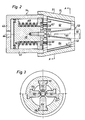
- the pressing tool 13 contains a guide sleeve 51 which is fastened to the hydraulic press 14 in the region of the cylinder cover 47.
- the guide sleeve has a conical interior 52, the largest diameter or base circle of which is adjacent to the plunger 48 and the smallest diameter or cover circle of which forms an opening 53 in the top surface of the press tool facing away from the press 14.
- four grooves 56, 57, 58, 59, offset by 90 ° and having a T-shaped cross section are incorporated (FIG. 3).
- the grooves run parallel to the surface lines of the conical interior and are therefore inclined at an angle ⁇ with respect to the longitudinal axis 61 of the pressing tool.
- the press jaws have a T-shaped cross section with a two-armed guide beam and a press ram protruding therefrom.
- Each press jaw is slidably mounted with its guide bar in an associated groove in the guide sleeve in the longitudinal direction of the press tool and connected to the pressure ram 48 by means of a screw 67, 68.
- the screw heads are guided in the plunger in radial slots 69, 71 in order not to block the displacement in the radial direction superimposed on any displacement of the pressing jaws in the axial direction.
- the inner surfaces of the press facing the center of the conical interior 52 jaws are inclined at an angle ⁇ with respect to the longitudinal axis 61.
- the direction of inclination of this angle ⁇ is opposite to the direction of inclination of the angle ⁇ , and the angle ⁇ is smaller than the angle ⁇ .
- the inner surfaces of the press jaws are circular in cross-section and have a surface profile that corresponds to a corresponding part of a nut piece for the conical external thread to be pressed.
- the feed device contains a housing 72, in which several and in the exemplary embodiment shown three piston-cylinder arrangements connected in series are installed.
- the first piston-cylinder arrangement consists of a first cylinder 73 permanently installed in the housing, to which pressure fluid lines 123 'and 123 und are connected.
- a cylinder 77 which is displaceable in the second housing 72 is fastened to the piston rod 76 of the piston 74 sliding in the first cylinder.
- the pressure fluid lines 223 'and 223 ⁇ are connected.
- On the piston rod 79 of the piston 78 sliding in the second cylinder a third cylinder 81 is attached to the pressure fluid lines 323 'and 323 ⁇ are connected.
- the piston 82 sliding in the third cylinder is rigidly connected by means of a piston rod 83 to a piston 84 of the length compensation device 71.
- the stroke of the pistons in the three piston-cylinder arrangements is of different lengths, which makes it possible to move the piston 84 in the length compensation device by predetermined total lengths by displacing one, two or even all three pistons.
- the working space 86 of length compensation Direction is connected to the hydraulic system 17 via the line 23A and is filled with the pressure fluid at the beginning of each working cycle, so that with each displacement of the piston 84 (to the right in FIG. 4) the cylinder 87, which, like the cylinders of the displacement device in the Housing 72 is slidably moved to the right.
- the cylinder 87 is mechanically or indirectly mechanically connected to the holding device 16 for the workpiece, so that the holding device 16 is also displaced in accordance with the displacement of the cylinder 87.
- a further pressure fluid line 23B is connected to the cylinder 87 of the length compensation device 71 or to the pressure fluid line 23A connected to this cylinder.
- This line contains a pressure relief valve 88, which opens as soon as the pressure in the working space 86 exceeds a predetermined value, as will be explained below.
- the "ON" button is first pressed on the control panel 37, which then activates the electronic control circuit 36 and the hydraulic system 17.
- the control circuit sets the valve 27 in a first position in which hydraulic fluid flows into the cylinder 41 of the press 14 and displaces the piston 42 against the force of the spring 49 (to the right in FIG. 2).
- the pressing jaws 62, 63, 64 and 65 are also displaced in the axial direction and, due to the inclination of the guide grooves 56, 57, 58, 59, are also moved together in the radial direction with respect to the longitudinal axis of the pressing tool until their side faces abut one another.
- valve 29 is also in a adjusted first position, in which the inflowing hydraulic fluid pulls the holding jaws of the holding device 16 apart in the radial direction.
- the rod-shaped workpiece 91 can then be inserted in the direction of the arrow 92 between the opened holding jaws as far as the stop on the compressed pressing jaws.
- the key data of the workpiece important for the cycle in particular the diameter of the workpiece, or the nominal diameter and the length of the conical thread to be pressed and at least one the material are entered into the electronic control circuit using the keypad on the control panel 27 characteristic of the workpiece.
- the entered characteristic values then determine which of several work programs stored in the control circuit is to be carried out.
- the work cycle begins as soon as the "START" button is pressed on the control panel.
- the valve 29 is switched to a second position in which the holding jaws move together until the workpiece is clamped.
- the valve 27 is controlled into its second position, in which the cylinder 41 of the press is ventilated and the spring 49 pulls the piston 42 together with the press jaws 62, 63, 64, 66 back into the rest position shown in FIG. 2.
- the valve 28 is controlled into a first position in which the hydraulic fluid flowing through displaces the feed device 12 and thus also the holding device 16 and the workpiece 91 held by it by a predetermined distance in the direction of the pressing tool 13 or between the pressing jaws .
- the valve 27 is controlled again into its first position, in which the pressing jaws are displaced in the axial direction and at the same time pressed together and pressed into the workpiece until their side faces abut one another.
- the pressure relief valve 88 opens and enables a rearward displacement of the cylinder 87 together with the holding device attached to it, until the pressure of the workpiece has dropped to a tolerable value.
- the valve 27 is controlled into the second position, whereby the press jaws are pulled apart again in the radial direction.
- the valve 26 is controlled into the first position, so that the rotating device 11 and with it the press 14 and the pressing tool are rotated 45 ° to the left.
- the valve 27 is again moved into the first position, the pressing jaws of the pressing tool being moved together again in the radial direction and the burr which has formed during the pressing of the conical thread in the region of the lateral edges of the pressing jaws being pressed out.
- the pressing jaws are first pulled apart again and then the pressing tool is turned 45 ° to the right into its starting position. The workpiece with a cold pressed ko African thread can then be removed from the device.
- the end of a work cycle is always the work steps six and seven described above, with which the burr that is unavoidable when pressing the conical thread is pressed into the workpiece.
- conical threads were pressed into reinforcing steels.
- Each reinforcing steel had a diameter of 40 mm.
- the conical thread had a cone of 6 °, a pitch of 4 mm and a flank angle of 90 °, corresponding to a pitch of 2 mm or half the pitch.
- the pressing tool used contained four pressing jaws, each of which had a cross section when viewed in the axial direction, that corresponded to a quarter circle.
- the pressure of the press was up to 650 bar in the axial direction, whereby a pressing pressure of the press jaws of up to 850 t was achieved in the radial direction.
- the described device and its devices can be modified in many ways and adapted to special working conditions.
- a press instead of a press that is moved hydraulically into the working position and into the rest position by means of a spring, a press can be used that is moved hydraulically in both directions.
- a feed device with only one cylinder can be used, the feed of which is controlled by the amount of hydraulic fluid introduced.
- the pressure relief valve 88 can also be connected to this cylinder and the longitudinal compensation device can be dispensed with.
- the device can be assembled from commercially available components and groups, and it is assumed that the electronic control and hydraulic system for controlling or actuating the individual devices are known to any person skilled in the art, for which reason a detailed description of these devices is dispensed with.
Landscapes
- Engineering & Computer Science (AREA)
- Mechanical Engineering (AREA)
- Forging (AREA)
- Metal Extraction Processes (AREA)
- Casting Or Compression Moulding Of Plastics Or The Like (AREA)
- Yarns And Mechanical Finishing Of Yarns Or Ropes (AREA)
Priority Applications (1)
| Application Number | Priority Date | Filing Date | Title |
|---|---|---|---|
| AT89810017T ATE102855T1 (de) | 1988-08-26 | 1989-01-11 | Verfahren zum kaltpressen eines konischen aussengewindes. |
Applications Claiming Priority (2)
| Application Number | Priority Date | Filing Date | Title |
|---|---|---|---|
| CH3190/88 | 1988-08-26 | ||
| CH3190/88A CH676564A5 (fr) | 1988-08-26 | 1988-08-26 |
Publications (3)
| Publication Number | Publication Date |
|---|---|
| EP0356375A2 true EP0356375A2 (fr) | 1990-02-28 |
| EP0356375A3 EP0356375A3 (fr) | 1991-01-16 |
| EP0356375B1 EP0356375B1 (fr) | 1994-03-16 |
Family
ID=4250591
Family Applications (1)
| Application Number | Title | Priority Date | Filing Date |
|---|---|---|---|
| EP89810017A Expired - Lifetime EP0356375B1 (fr) | 1988-08-26 | 1989-01-11 | Procédé à matricer à froid un filet extérieur conique |
Country Status (6)
| Country | Link |
|---|---|
| US (1) | US4941341A (fr) |
| EP (1) | EP0356375B1 (fr) |
| AT (1) | ATE102855T1 (fr) |
| CA (1) | CA1318990C (fr) |
| CH (1) | CH676564A5 (fr) |
| DE (1) | DE58907213D1 (fr) |
Cited By (2)
| Publication number | Priority date | Publication date | Assignee | Title |
|---|---|---|---|---|
| DE102007062830A1 (de) | 2007-12-21 | 2009-06-25 | Ifm Electronic Gmbh | Verfahren und Vorrichtung zum Herstellen eines Gewindes sowie Bauteil und Gerät |
| DE102008063692A1 (de) | 2007-12-21 | 2009-07-09 | Ifm Electronic Gmbh | Verfahren und Vorrichtung zum Herstellen eines Gewindes sowie Bauteil und Gerät |
Families Citing this family (2)
| Publication number | Priority date | Publication date | Assignee | Title |
|---|---|---|---|---|
| US5836197A (en) * | 1996-12-16 | 1998-11-17 | Mckee Machine Tool Corp. | Integral machine tool assemblies |
| KR101894848B1 (ko) * | 2014-02-28 | 2018-09-05 | 현대자동차주식회사 | 오스테나이트계 내열합금 및 이를 이용한 내열볼트의 제조방법 |
Family Cites Families (13)
| Publication number | Priority date | Publication date | Assignee | Title |
|---|---|---|---|---|
| US408294A (en) * | 1889-08-06 | Swag ing-machine | ||
| US228033A (en) * | 1880-05-25 | Device for swaging screw-threads on eyebolts | ||
| US859803A (en) * | 1906-03-28 | 1907-07-09 | Cummings Machine Company | Threaded tube. |
| US1466302A (en) * | 1920-04-26 | 1923-08-28 | Jouve Felix Louis | Machine for swaging or reducing metal |
| US1712108A (en) * | 1926-10-01 | 1929-05-07 | Robert A Goeller | Connecter |
| US2160694A (en) * | 1936-07-09 | 1939-05-30 | Thomas & Betts Corp | Wire connector |
| US2225345A (en) * | 1938-09-17 | 1940-12-17 | Bendix Aviat Corp | Banding press |
| US2652577A (en) * | 1946-04-27 | 1953-09-22 | Bulloneria E Viteria Italiana | Machine for producing articles from blank stock |
| US3154978A (en) * | 1962-07-09 | 1964-11-03 | United Wire & Supply Corp | Tube pointer |
| US3370451A (en) * | 1965-06-28 | 1968-02-27 | Blaw Knox Co | Apparatus and method for pointing tubes |
| US3417598A (en) * | 1966-08-19 | 1968-12-24 | Manco Mfg Co | Apparatus for pointing work pieces |
| US4751839A (en) * | 1980-05-09 | 1988-06-21 | Ltv Steel Company, Inc. | Method for removing certain of the corrugations in a helically corrugated pipe |
| CH665152A5 (de) * | 1985-01-10 | 1988-04-29 | Urs Kellner | Verfahren zum herstellen eines konischen aussengewindes. |
-
1988
- 1988-08-26 CH CH3190/88A patent/CH676564A5/de not_active IP Right Cessation
-
1989
- 1989-01-11 DE DE89810017T patent/DE58907213D1/de not_active Expired - Fee Related
- 1989-01-11 EP EP89810017A patent/EP0356375B1/fr not_active Expired - Lifetime
- 1989-01-11 AT AT89810017T patent/ATE102855T1/de not_active IP Right Cessation
- 1989-01-20 CA CA000588799A patent/CA1318990C/fr not_active Expired - Fee Related
- 1989-01-23 US US07/300,489 patent/US4941341A/en not_active Expired - Lifetime
Cited By (3)
| Publication number | Priority date | Publication date | Assignee | Title |
|---|---|---|---|---|
| DE102007062830A1 (de) | 2007-12-21 | 2009-06-25 | Ifm Electronic Gmbh | Verfahren und Vorrichtung zum Herstellen eines Gewindes sowie Bauteil und Gerät |
| DE102008063692A1 (de) | 2007-12-21 | 2009-07-09 | Ifm Electronic Gmbh | Verfahren und Vorrichtung zum Herstellen eines Gewindes sowie Bauteil und Gerät |
| DE102007062830B4 (de) * | 2007-12-21 | 2014-11-27 | Ifm Electronic Gmbh | Verfahren und Vorrichtung zum Herstellen eines Gewindes sowie Bauteil und Gerät |
Also Published As
| Publication number | Publication date |
|---|---|
| CA1318990C (fr) | 1993-06-15 |
| ATE102855T1 (de) | 1994-04-15 |
| US4941341A (en) | 1990-07-17 |
| EP0356375B1 (fr) | 1994-03-16 |
| EP0356375A3 (fr) | 1991-01-16 |
| DE58907213D1 (de) | 1994-04-21 |
| CH676564A5 (fr) | 1991-02-15 |
Similar Documents
| Publication | Publication Date | Title |
|---|---|---|
| EP0187623B1 (fr) | Dispositif pour matricer à froid d'un filetage effilé | |
| DE69317303T3 (de) | Selbststanzende nieten | |
| DE2610467A1 (de) | Vorrichtung zum ablaengen von rohren | |
| DE10118664B4 (de) | Spanneinrichtung für zu bearbeitende Werkstücke mit Unwuchtausgleich | |
| EP0185883A2 (fr) | Mandrin à mors actionné mécaniquement | |
| EP0798063B1 (fr) | Outil à aléser | |
| DE3423543A1 (de) | Presse und verfahren zur herstellung derselben | |
| DE1948119A1 (de) | Vorrichtung zum Abschraegen der Kanten eines verzahnten Werkstuecks | |
| EP0356375B1 (fr) | Procédé à matricer à froid un filet extérieur conique | |
| EP0183031A2 (fr) | Procédé pour la fabrication d'alésages ayant une surface de haute qualité et dispositif pour la mise en oeuvre du procédé | |
| DE29824688U1 (de) | Radialpresse | |
| DE1602064A1 (de) | Verfahren zur Herstellung sich allmaehlich verjuengender Walzprofile und Maschine zu seiner Durchfuehrung | |
| DE2631583B2 (de) | Kraftbetätigtes Spannfutter | |
| DE3413285A1 (de) | Spannvorrichtung fuer werkzeuge, wie bohrer, fraeser oder dgl. | |
| DE1752716A1 (de) | Verfahren zum maschinellen Biegen von Draht- und Bandmaterial und Maschine zur Durchfuehrung des Verfahrens | |
| DE580175C (de) | Vorrichtung zum Festklemmen der schaltbaren Werkzeug- oder Werkstuecktrommel bei mehrspindligen, selbsttaetigen Drehbaenken | |
| DE19611611A1 (de) | Presse | |
| EP0380739B1 (fr) | Procédé et dispositif pour serrer temporairement des pièces à usiner | |
| DE2512654A1 (de) | Dornausziehvorrichtung fuer pilgerwalzwerke | |
| DE10251821B3 (de) | Hydraulisches Zeitglied | |
| DE2707476C3 (de) | Vorrichtung zum Verbinden winklig aneinanderstoßender Schaltafeln | |
| AT524952B1 (de) | Kettenfräsvorrichtung zum Ausfräsen einer taschenförmigen Ausnehmung in einer Möbelplatte zur Aufnahme eines Möbelbeschlags | |
| DE2550216C2 (de) | Vorrichtung zum kontinuierlichen Strangpressen von Draht | |
| DE102025128661A1 (de) | Spannvorrichtung, Spannsystem und Verfahren zum Festspannen eines Werkstücks auf einer Werkstückauflage | |
| CH690542A5 (de) | Werkstückspannvorrichtung für eine Werkzeugmaschine. |
Legal Events
| Date | Code | Title | Description |
|---|---|---|---|
| PUAI | Public reference made under article 153(3) epc to a published international application that has entered the european phase |
Free format text: ORIGINAL CODE: 0009012 |
|
| AK | Designated contracting states |
Kind code of ref document: A2 Designated state(s): AT BE DE ES FR GB GR IT LU NL SE |
|
| PUAL | Search report despatched |
Free format text: ORIGINAL CODE: 0009013 |
|
| AK | Designated contracting states |
Kind code of ref document: A3 Designated state(s): AT BE DE ES FR GB GR IT LU NL SE |
|
| 17P | Request for examination filed |
Effective date: 19910406 |
|
| 17Q | First examination report despatched |
Effective date: 19911112 |
|
| RAP1 | Party data changed (applicant data changed or rights of an application transferred) |
Owner name: BBR BAUVERFAHREN AG |
|
| GRAA | (expected) grant |
Free format text: ORIGINAL CODE: 0009210 |
|
| AK | Designated contracting states |
Kind code of ref document: B1 Designated state(s): AT BE DE ES FR GB GR IT LU NL SE |
|
| PG25 | Lapsed in a contracting state [announced via postgrant information from national office to epo] |
Ref country code: GR Free format text: LAPSE BECAUSE OF FAILURE TO SUBMIT A TRANSLATION OF THE DESCRIPTION OR TO PAY THE FEE WITHIN THE PRESCRIBED TIME-LIMIT Effective date: 19940316 Ref country code: ES Free format text: THE PATENT HAS BEEN ANNULLED BY A DECISION OF A NATIONAL AUTHORITY Effective date: 19940316 |
|
| REF | Corresponds to: |
Ref document number: 102855 Country of ref document: AT Date of ref document: 19940415 Kind code of ref document: T |
|
| ITF | It: translation for a ep patent filed | ||
| REF | Corresponds to: |
Ref document number: 58907213 Country of ref document: DE Date of ref document: 19940421 |
|
| GBT | Gb: translation of ep patent filed (gb section 77(6)(a)/1977) |
Effective date: 19940407 |
|
| ET | Fr: translation filed | ||
| PLBE | No opposition filed within time limit |
Free format text: ORIGINAL CODE: 0009261 |
|
| STAA | Information on the status of an ep patent application or granted ep patent |
Free format text: STATUS: NO OPPOSITION FILED WITHIN TIME LIMIT |
|
| EAL | Se: european patent in force in sweden |
Ref document number: 89810017.7 |
|
| PG25 | Lapsed in a contracting state [announced via postgrant information from national office to epo] |
Ref country code: LU Free format text: LAPSE BECAUSE OF NON-PAYMENT OF DUE FEES Effective date: 19950131 |
|
| 26N | No opposition filed | ||
| PG25 | Lapsed in a contracting state [announced via postgrant information from national office to epo] |
Ref country code: NL Effective date: 19950801 |
|
| PG25 | Lapsed in a contracting state [announced via postgrant information from national office to epo] |
Ref country code: FR Effective date: 19950929 |
|
| NLV4 | Nl: lapsed or anulled due to non-payment of the annual fee |
Effective date: 19950801 |
|
| REG | Reference to a national code |
Ref country code: FR Ref legal event code: ST |
|
| PGFP | Annual fee paid to national office [announced via postgrant information from national office to epo] |
Ref country code: BE Payment date: 19981211 Year of fee payment: 11 |
|
| PGFP | Annual fee paid to national office [announced via postgrant information from national office to epo] |
Ref country code: GB Payment date: 19981221 Year of fee payment: 11 |
|
| PGFP | Annual fee paid to national office [announced via postgrant information from national office to epo] |
Ref country code: SE Payment date: 19990114 Year of fee payment: 11 |
|
| PGFP | Annual fee paid to national office [announced via postgrant information from national office to epo] |
Ref country code: AT Payment date: 19990121 Year of fee payment: 11 |
|
| PGFP | Annual fee paid to national office [announced via postgrant information from national office to epo] |
Ref country code: DE Payment date: 19990330 Year of fee payment: 11 |
|
| PG25 | Lapsed in a contracting state [announced via postgrant information from national office to epo] |
Ref country code: GB Free format text: LAPSE BECAUSE OF NON-PAYMENT OF DUE FEES Effective date: 20000111 Ref country code: AT Free format text: LAPSE BECAUSE OF NON-PAYMENT OF DUE FEES Effective date: 20000111 |
|
| PG25 | Lapsed in a contracting state [announced via postgrant information from national office to epo] |
Ref country code: SE Free format text: LAPSE BECAUSE OF NON-PAYMENT OF DUE FEES Effective date: 20000112 |
|
| PG25 | Lapsed in a contracting state [announced via postgrant information from national office to epo] |
Ref country code: BE Free format text: LAPSE BECAUSE OF NON-PAYMENT OF DUE FEES Effective date: 20000131 |
|
| BERE | Be: lapsed |
Owner name: BBR BAUVERFAHREN A.G. Effective date: 20000131 |
|
| GBPC | Gb: european patent ceased through non-payment of renewal fee |
Effective date: 20000111 |
|
| EUG | Se: european patent has lapsed |
Ref document number: 89810017.7 |
|
| PG25 | Lapsed in a contracting state [announced via postgrant information from national office to epo] |
Ref country code: DE Free format text: LAPSE BECAUSE OF NON-PAYMENT OF DUE FEES Effective date: 20001101 |
|
| PG25 | Lapsed in a contracting state [announced via postgrant information from national office to epo] |
Ref country code: IT Free format text: LAPSE BECAUSE OF NON-PAYMENT OF DUE FEES;WARNING: LAPSES OF ITALIAN PATENTS WITH EFFECTIVE DATE BEFORE 2007 MAY HAVE OCCURRED AT ANY TIME BEFORE 2007. THE CORRECT EFFECTIVE DATE MAY BE DIFFERENT FROM THE ONE RECORDED. Effective date: 20050111 |