EP0356534A1 - Chambre à tourbillon pour moteurs diesel et similaires - Google Patents
Chambre à tourbillon pour moteurs diesel et similaires Download PDFInfo
- Publication number
- EP0356534A1 EP0356534A1 EP88113018A EP88113018A EP0356534A1 EP 0356534 A1 EP0356534 A1 EP 0356534A1 EP 88113018 A EP88113018 A EP 88113018A EP 88113018 A EP88113018 A EP 88113018A EP 0356534 A1 EP0356534 A1 EP 0356534A1
- Authority
- EP
- European Patent Office
- Prior art keywords
- insulating member
- engine
- swirl chamber
- recess
- aperture
- Prior art date
- Legal status (The legal status is an assumption and is not a legal conclusion. Google has not performed a legal analysis and makes no representation as to the accuracy of the status listed.)
- Withdrawn
Links
Images

Classifications
-
- F—MECHANICAL ENGINEERING; LIGHTING; HEATING; WEAPONS; BLASTING
- F02—COMBUSTION ENGINES; HOT-GAS OR COMBUSTION-PRODUCT ENGINE PLANTS
- F02B—INTERNAL-COMBUSTION PISTON ENGINES; COMBUSTION ENGINES IN GENERAL
- F02B19/00—Engines characterised by precombustion chambers
- F02B19/16—Chamber shapes or constructions not specific to sub-groups F02B19/02 - F02B19/10
- F02B19/165—The shape or construction of the pre-combustion chambers is specially adapted to be formed, at least in part, of ceramic material
-
- F—MECHANICAL ENGINEERING; LIGHTING; HEATING; WEAPONS; BLASTING
- F02—COMBUSTION ENGINES; HOT-GAS OR COMBUSTION-PRODUCT ENGINE PLANTS
- F02B—INTERNAL-COMBUSTION PISTON ENGINES; COMBUSTION ENGINES IN GENERAL
- F02B3/00—Engines characterised by air compression and subsequent fuel addition
- F02B3/06—Engines characterised by air compression and subsequent fuel addition with compression ignition
-
- Y—GENERAL TAGGING OF NEW TECHNOLOGICAL DEVELOPMENTS; GENERAL TAGGING OF CROSS-SECTIONAL TECHNOLOGIES SPANNING OVER SEVERAL SECTIONS OF THE IPC; TECHNICAL SUBJECTS COVERED BY FORMER USPC CROSS-REFERENCE ART COLLECTIONS [XRACs] AND DIGESTS
- Y02—TECHNOLOGIES OR APPLICATIONS FOR MITIGATION OR ADAPTATION AGAINST CLIMATE CHANGE
- Y02T—CLIMATE CHANGE MITIGATION TECHNOLOGIES RELATED TO TRANSPORTATION
- Y02T10/00—Road transport of goods or passengers
- Y02T10/10—Internal combustion engine [ICE] based vehicles
- Y02T10/12—Improving ICE efficiencies
Definitions
- the present invention relates to a swirl chamber type Diesel engine and more specifically to such a type of engine wherein the swirl chamber is defined within ceramic inserts which inserts are fitted into a recess formed in an alloy engine cylinder head and which improve the thermal efficiency of the engine by limiting the amount of heat which is lost through the swirl chamber walls.
- JM-A-60-171931 discloses a swirl chamber of the nature shown in Fig. 1.
- This arrangement includes a piston 1 which is reciprocatively disposed in a cylinder 2.
- the top of the cylinder is closed by a cyinder head 3 in a manner to define a variable volume main combustion chamber 4 therein.
- the cylinder head 3 is formed with a cavity (no numeral) in which a swirl chamber 5 is defined by a ceramic hot plug 6 and a ceramic dome member 7.
- a fuel injector 8 and a glow plug 9 are arranged to project into the swirl chamber through apertures 8a and 9a formed in the ceramic dome member 7.
- a dome shaped ceramic insert which defines a portion of a swirl chamber, is formed at the crown portion with a single aperture through which both the fuel injector and the glow plug can extend.
- the cylinder head is formed with a portion which fits into the aperture and which has a wall portion which cooperates with the inner walls of the insert to define the upper section of the swirl chamber.
- a first aspect of the present invention is deemed to comprise a swirl chamber type internal combustion engine which engine features: a thermally insulating member disposed in a recess formed in a metallic cylinder head, said insulating member including a cavity which defines a portion of said swirl chamber; means defining an aperture in said insulating member; and means defining a metallic projection which fits into said aperture, said projection including first and second bores, said first and second bores being arranged to receive first and second devices which are essential to the operation of the engine.
- a second aspect of the invention is deemed to comprise an engine which features: a cylinder defined in a cylinder block; a piston reciprocatively disposed in said cyinder; a cylinder head secured to said cylinder block in a manner to close the clinder and to define a main variable volume combustion chamber, said cylinder head being formed of a metal and including a recess; a thermally insulating member disposed in said recess, said insulating member forming a portion of a swirl chamber which is fluidly communicated with said main variable volume combustion chamber; and means defining a single opening in said insulating through which a fuel injector and a glow plug extend operatively into said swirl chamber.
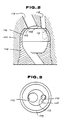
- Figs. 2 and 3 show a first embodiment of the present invention.
- an aluminium alloy cylinder head 100 is formed with a shaped recess (no numeral) into which a ceramic hot plug 102, and a ceramic dome shaped member 104 are force fitted.
- the upper or crown portion of the dome member 104 is formed with an essentially circular aperture 106.
- the portion of the cylinder head into which the dome member 106 is disposed is shaped in the manner shown in Fig. 2 to have a projection which fits into the aperture.
- This projection has a wall portion 108 which defines the upper portion of the swirl chamber and cooperates with the inner wall of the dome member 104 to define an essentially continuous swirl chamber surface.
- Bores 110, 112 in which a fuel injector and a glow plug are disposable, are formed in the cylinder head 100 in a manner to fall within the perimeter of the essentially circular opening 106.
- the open topped dome member 104 is formed with a semi-circular recess 114 which opens into the circular recess 106 in a manner as shown in Fig. 3.
- the section of the swirl chamber which extends between the fuel injector and the glow plug receiving bores 110 and 112 is defined by the same metal (viz., aluminimum alloy) as that which defines the main body of the cylinder head 100. Accordingly, this section of the swirl chamber exhibits relatively high thermal conductivity as compared with the ceramic members 102, 104 and accordingly obviates the formation of a large stress inducing temperature differential.
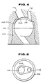
- Figs. 4 and 5 show a second embodiment of the present invention.
- the aperture formed in the top of the dome member is shaped in a manner to reduce the area of thermally conductive metallic alloy material which is exposed to the high temperature combustion gases.
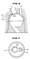
- Figs. 6 and 7 show a third embodiment of the present invention. This embodiment is similar to the second one and features a shaped aperture 306 which further minimizes the amount of metal allow surface area which is exposed to combustion gases while remove the section of ceramic material which tends to develop cracks due to the concentration of thermally induced stress.
- the application and use of the second and third embodiments is essentially identical to the first one.
- the dome members of these embodiments are formed of a ceramic material, the shaped openings which characterize the same are readily formed by casting and in a manner which obviates the need for cost increasing machining and the like.
Landscapes
- Engineering & Computer Science (AREA)
- Chemical & Material Sciences (AREA)
- Ceramic Engineering (AREA)
- Combustion & Propulsion (AREA)
- Mechanical Engineering (AREA)
- General Engineering & Computer Science (AREA)
- Combustion Methods Of Internal-Combustion Engines (AREA)
Priority Applications (1)
| Application Number | Priority Date | Filing Date | Title |
|---|---|---|---|
| EP88113018A EP0356534A1 (fr) | 1988-08-10 | 1988-08-10 | Chambre à tourbillon pour moteurs diesel et similaires |
Applications Claiming Priority (1)
| Application Number | Priority Date | Filing Date | Title |
|---|---|---|---|
| EP88113018A EP0356534A1 (fr) | 1988-08-10 | 1988-08-10 | Chambre à tourbillon pour moteurs diesel et similaires |
Publications (1)
| Publication Number | Publication Date |
|---|---|
| EP0356534A1 true EP0356534A1 (fr) | 1990-03-07 |
Family
ID=8199194
Family Applications (1)
| Application Number | Title | Priority Date | Filing Date |
|---|---|---|---|
| EP88113018A Withdrawn EP0356534A1 (fr) | 1988-08-10 | 1988-08-10 | Chambre à tourbillon pour moteurs diesel et similaires |
Country Status (1)
| Country | Link |
|---|---|
| EP (1) | EP0356534A1 (fr) |
Citations (4)
| Publication number | Priority date | Publication date | Assignee | Title |
|---|---|---|---|---|
| FR1344892A (fr) * | 1962-05-28 | 1963-12-06 | Applic Tech Ind Lati | Perfectionnements aux moteurs à combustion interne à injection de carburant |
| FR2380422A1 (fr) * | 1977-02-09 | 1978-09-08 | Daimler Benz Ag | Element de construction soumis a des sollicitations thermiques, en partie d'un tel element |
| DE2813594A1 (de) * | 1978-03-30 | 1979-10-04 | Kloeckner Humboldt Deutz Ag | Einspritzbrennkraftmaschine mit einem nebenbrennraum im zylinderkopf |
| EP0141540A2 (fr) * | 1983-10-06 | 1985-05-15 | Mazda Motor Corporation | Chambre de combustion divisée pour moteur diesel |
-
1988
- 1988-08-10 EP EP88113018A patent/EP0356534A1/fr not_active Withdrawn
Patent Citations (4)
| Publication number | Priority date | Publication date | Assignee | Title |
|---|---|---|---|---|
| FR1344892A (fr) * | 1962-05-28 | 1963-12-06 | Applic Tech Ind Lati | Perfectionnements aux moteurs à combustion interne à injection de carburant |
| FR2380422A1 (fr) * | 1977-02-09 | 1978-09-08 | Daimler Benz Ag | Element de construction soumis a des sollicitations thermiques, en partie d'un tel element |
| DE2813594A1 (de) * | 1978-03-30 | 1979-10-04 | Kloeckner Humboldt Deutz Ag | Einspritzbrennkraftmaschine mit einem nebenbrennraum im zylinderkopf |
| EP0141540A2 (fr) * | 1983-10-06 | 1985-05-15 | Mazda Motor Corporation | Chambre de combustion divisée pour moteur diesel |
Non-Patent Citations (2)
| Title |
|---|
| PATENT ABSTRACTS OF JAPAN, vol. 10, no. 365 (M-542)[2422], 6th December 1986; & JP-A-61 160 515 (MAZDA MOTOR CORP.) 21-07-1986 * |
| PATENT ABSTRACTS OF JAPAN, vol. 9, no. 155 (M-392)[1878], 29th June 1985; & JP-A-60 30 421 (NIPPON TOKUSHU TOGYO K.K.) 16-02-1985 * |
Similar Documents
| Publication | Publication Date | Title |
|---|---|---|
| EP2978962B1 (fr) | Gestion thermique d'un piston dans un moteur à pistons opposés | |
| US4875444A (en) | Swirl chamber for diesel engines and the like | |
| US4939984A (en) | Investment-cast piston crown cap with encapsulated non-metallic insulating core | |
| US4651692A (en) | Structure of divided combustion chamber for diesel engine | |
| JPS6445918A (en) | Combustion chamber for diesel engine | |
| DE321159T1 (de) | Isolierte brennkraftmaschine. | |
| EP0356534A1 (fr) | Chambre à tourbillon pour moteurs diesel et similaires | |
| US2622579A (en) | Combustion chamber for internal-combustion engines | |
| CN115051242A (zh) | 火花塞 | |
| GB2081809A (en) | Direct Fuel Injection Internal Combustion Engine | |
| US4562806A (en) | Cylinder head for internal combustion engines with compression ignition | |
| GB2164701A (en) | Piston for direct injection diesel engine | |
| US2659355A (en) | Combustion chamber of internalcombustion engines | |
| JPS6226319A (ja) | 内燃機関のセラミツクス製副室 | |
| US4557230A (en) | Swirl chamber for internal combustion engine | |
| JPS6319566Y2 (fr) | ||
| JPH0598966A (ja) | 火花点火式エンジンのスキツシユ構造 | |
| JPH0610414B2 (ja) | エンジンの副室構造 | |
| JPS6350426Y2 (fr) | ||
| JP3573036B2 (ja) | ピストン構造 | |
| GB2144487A (en) | A reciprocating piston i.c. engine combustion chambers | |
| JPS5939158Y2 (ja) | 2サイクルエンジンの燃焼室 | |
| JPH0236900Y2 (fr) | ||
| JPH0454215A (ja) | ディーゼルエンジンのアルミ合金製シリンダヘッドのうず室式燃焼室 | |
| JPH0134663Y2 (fr) |
Legal Events
| Date | Code | Title | Description |
|---|---|---|---|
| PUAI | Public reference made under article 153(3) epc to a published international application that has entered the european phase |
Free format text: ORIGINAL CODE: 0009012 |
|
| 17P | Request for examination filed |
Effective date: 19880810 |
|
| AK | Designated contracting states |
Kind code of ref document: A1 Designated state(s): DE GB |
|
| 17Q | First examination report despatched |
Effective date: 19910225 |
|
| STAA | Information on the status of an ep patent application or granted ep patent |
Free format text: STATUS: THE APPLICATION IS DEEMED TO BE WITHDRAWN |
|
| 18D | Application deemed to be withdrawn |
Effective date: 19911108 |