EP0356546A1 - Verfahren und Vorrichtung zur kryogenen Entnahme - Google Patents
Verfahren und Vorrichtung zur kryogenen Entnahme Download PDFInfo
- Publication number
- EP0356546A1 EP0356546A1 EP88114126A EP88114126A EP0356546A1 EP 0356546 A1 EP0356546 A1 EP 0356546A1 EP 88114126 A EP88114126 A EP 88114126A EP 88114126 A EP88114126 A EP 88114126A EP 0356546 A1 EP0356546 A1 EP 0356546A1
- Authority
- EP
- European Patent Office
- Prior art keywords
- vessel
- liquid
- tube
- gas
- withdrawal
- Prior art date
- Legal status (The legal status is an assumption and is not a legal conclusion. Google has not performed a legal analysis and makes no representation as to the accuracy of the status listed.)
- Withdrawn
Links
- 238000000034 method Methods 0.000 title claims abstract description 8
- 239000007788 liquid Substances 0.000 claims abstract description 50
- 230000033228 biological regulation Effects 0.000 claims description 3
- 238000001816 cooling Methods 0.000 claims 1
- 238000010438 heat treatment Methods 0.000 abstract description 9
- 239000007789 gas Substances 0.000 description 42
- 239000012530 fluid Substances 0.000 description 5
- 239000000463 material Substances 0.000 description 4
- QVGXLLKOCUKJST-UHFFFAOYSA-N atomic oxygen Chemical compound [O] QVGXLLKOCUKJST-UHFFFAOYSA-N 0.000 description 3
- 239000001273 butane Substances 0.000 description 3
- IJDNQMDRQITEOD-UHFFFAOYSA-N n-butane Chemical compound CCCC IJDNQMDRQITEOD-UHFFFAOYSA-N 0.000 description 3
- OFBQJSOFQDEBGM-UHFFFAOYSA-N n-pentane Natural products CCCCC OFBQJSOFQDEBGM-UHFFFAOYSA-N 0.000 description 3
- 239000001301 oxygen Substances 0.000 description 3
- 229910052760 oxygen Inorganic materials 0.000 description 3
- QGZKDVFQNNGYKY-UHFFFAOYSA-N Ammonia Chemical compound N QGZKDVFQNNGYKY-UHFFFAOYSA-N 0.000 description 2
- XKRFYHLGVUSROY-UHFFFAOYSA-N Argon Chemical compound [Ar] XKRFYHLGVUSROY-UHFFFAOYSA-N 0.000 description 2
- IJGRMHOSHXDMSA-UHFFFAOYSA-N Atomic nitrogen Chemical compound N#N IJGRMHOSHXDMSA-UHFFFAOYSA-N 0.000 description 2
- GQPLMRYTRLFLPF-UHFFFAOYSA-N Nitrous Oxide Chemical compound [O-][N+]#N GQPLMRYTRLFLPF-UHFFFAOYSA-N 0.000 description 2
- VNWKTOKETHGBQD-UHFFFAOYSA-N methane Chemical compound C VNWKTOKETHGBQD-UHFFFAOYSA-N 0.000 description 2
- CURLTUGMZLYLDI-UHFFFAOYSA-N Carbon dioxide Chemical compound O=C=O CURLTUGMZLYLDI-UHFFFAOYSA-N 0.000 description 1
- UGFAIRIUMAVXCW-UHFFFAOYSA-N Carbon monoxide Chemical compound [O+]#[C-] UGFAIRIUMAVXCW-UHFFFAOYSA-N 0.000 description 1
- OTMSDBZUPAUEDD-UHFFFAOYSA-N Ethane Chemical compound CC OTMSDBZUPAUEDD-UHFFFAOYSA-N 0.000 description 1
- VGGSQFUCUMXWEO-UHFFFAOYSA-N Ethene Chemical compound C=C VGGSQFUCUMXWEO-UHFFFAOYSA-N 0.000 description 1
- 239000005977 Ethylene Substances 0.000 description 1
- 239000012080 ambient air Substances 0.000 description 1
- 229910021529 ammonia Inorganic materials 0.000 description 1
- 229910052786 argon Inorganic materials 0.000 description 1
- 235000013405 beer Nutrition 0.000 description 1
- 230000005540 biological transmission Effects 0.000 description 1
- 229910002092 carbon dioxide Inorganic materials 0.000 description 1
- 229910002091 carbon monoxide Inorganic materials 0.000 description 1
- 239000004020 conductor Substances 0.000 description 1
- 230000007423 decrease Effects 0.000 description 1
- 238000002309 gasification Methods 0.000 description 1
- 239000001307 helium Substances 0.000 description 1
- 229910052734 helium Inorganic materials 0.000 description 1
- SWQJXJOGLNCZEY-UHFFFAOYSA-N helium atom Chemical compound [He] SWQJXJOGLNCZEY-UHFFFAOYSA-N 0.000 description 1
- 239000001257 hydrogen Substances 0.000 description 1
- 229910052739 hydrogen Inorganic materials 0.000 description 1
- 125000004435 hydrogen atom Chemical class [H]* 0.000 description 1
- 229910052757 nitrogen Inorganic materials 0.000 description 1
- 239000001272 nitrous oxide Substances 0.000 description 1
- 238000009877 rendering Methods 0.000 description 1
- 238000007789 sealing Methods 0.000 description 1
- 235000014214 soft drink Nutrition 0.000 description 1
- 229910001220 stainless steel Inorganic materials 0.000 description 1
- 230000008016 vaporization Effects 0.000 description 1
- 238000009834 vaporization Methods 0.000 description 1
- 239000006200 vaporizer Substances 0.000 description 1
- XLYOFNOQVPJJNP-UHFFFAOYSA-N water Substances O XLYOFNOQVPJJNP-UHFFFAOYSA-N 0.000 description 1
Images


Classifications
-
- F—MECHANICAL ENGINEERING; LIGHTING; HEATING; WEAPONS; BLASTING
- F17—STORING OR DISTRIBUTING GASES OR LIQUIDS
- F17C—VESSELS FOR CONTAINING OR STORING COMPRESSED, LIQUEFIED OR SOLIDIFIED GASES; FIXED-CAPACITY GAS-HOLDERS; FILLING VESSELS WITH, OR DISCHARGING FROM VESSELS, COMPRESSED, LIQUEFIED, OR SOLIDIFIED GASES
- F17C9/00—Methods or apparatus for discharging liquefied or solidified gases from vessels not under pressure
- F17C9/02—Methods or apparatus for discharging liquefied or solidified gases from vessels not under pressure with change of state, e.g. vaporisation
-
- F—MECHANICAL ENGINEERING; LIGHTING; HEATING; WEAPONS; BLASTING
- F17—STORING OR DISTRIBUTING GASES OR LIQUIDS
- F17C—VESSELS FOR CONTAINING OR STORING COMPRESSED, LIQUEFIED OR SOLIDIFIED GASES; FIXED-CAPACITY GAS-HOLDERS; FILLING VESSELS WITH, OR DISCHARGING FROM VESSELS, COMPRESSED, LIQUEFIED, OR SOLIDIFIED GASES
- F17C9/00—Methods or apparatus for discharging liquefied or solidified gases from vessels not under pressure
-
- F—MECHANICAL ENGINEERING; LIGHTING; HEATING; WEAPONS; BLASTING
- F17—STORING OR DISTRIBUTING GASES OR LIQUIDS
- F17C—VESSELS FOR CONTAINING OR STORING COMPRESSED, LIQUEFIED OR SOLIDIFIED GASES; FIXED-CAPACITY GAS-HOLDERS; FILLING VESSELS WITH, OR DISCHARGING FROM VESSELS, COMPRESSED, LIQUEFIED, OR SOLIDIFIED GASES
- F17C2227/00—Transfer of fluids, i.e. method or means for transferring the fluid; Heat exchange with the fluid
- F17C2227/03—Heat exchange with the fluid
- F17C2227/0302—Heat exchange with the fluid by heating
- F17C2227/0309—Heat exchange with the fluid by heating using another fluid
- F17C2227/0323—Heat exchange with the fluid by heating using another fluid in a closed loop
-
- Y—GENERAL TAGGING OF NEW TECHNOLOGICAL DEVELOPMENTS; GENERAL TAGGING OF CROSS-SECTIONAL TECHNOLOGIES SPANNING OVER SEVERAL SECTIONS OF THE IPC; TECHNICAL SUBJECTS COVERED BY FORMER USPC CROSS-REFERENCE ART COLLECTIONS [XRACs] AND DIGESTS
- Y02—TECHNOLOGIES OR APPLICATIONS FOR MITIGATION OR ADAPTATION AGAINST CLIMATE CHANGE
- Y02E—REDUCTION OF GREENHOUSE GAS [GHG] EMISSIONS, RELATED TO ENERGY GENERATION, TRANSMISSION OR DISTRIBUTION
- Y02E60/00—Enabling technologies; Technologies with a potential or indirect contribution to GHG emissions mitigation
- Y02E60/30—Hydrogen technology
- Y02E60/32—Hydrogen storage
Definitions
- U.S. Patent No. 2,971,345 contemplates a device for withdrawing liquid butane from a vessel.
- the device includes a storage vessel, a vaporizer and a pump. In operation, a portion of the butane withdrawn from the vessel is vaporized and subsequently recycled to the vessel. Another portion on the butane is sent to a receiving means.
- U.S. Patent No. 3,216,209 (Krigsman) is directed to an apparatus for maintaining a fluid in a supercritical state.
- the apparatus is provided with a heating coil within a storage vessel and a heating coil external to the storage vessel. Fluid that is withdrawn from the storage vessel flows through the heating coils to maintain it in a supercritical state.
- U.S. Patent No. 3,696,627 discloses a system for transferring a liquefied gas at a constant temperature, pressure and flow rate.
- the system consists of three nested tubes.
- the innermost tube withdraws the liquefied gas.
- the middle tube subcools the liquefied gas in the inner tube and the outermost tube absorbs heat from the surrounding atmosphere through a jacketing fluid.
- U.S. Patent No. 4,317,269 discloses a device for revaporizing a liquefied gas that is stored in an insulated vessel.
- the device includes a series of nested tubes through which water flows. As the liquefied gas contacts the nested tubes, it is vaporized.
- a significant disadvantage of prior systems for withdrawing and gasifying cryogenic liquids has been that the withdrawal rate is impeded or even stopped when the pressure of the gas in the head space above the liquid in the insulated vessel is lowered because the liquid is withdrawn faster than it can vaporize within the vessel and replenish the head pressure.
- This invention concerns a method and apparatus for withdrawing or gasifying a cryogenic liquid from an insulated vessel.
- the apparatus comprises a withdrawal tube and a heat exchanger set so that when the tube and heat exchanger are brought into sealing engagement with the vessel, the withdrawal tube and heat exchanger are immersed in the liquid in the vessel.
- the heat exchanger preferably consists of an inner tube nested within, and connected to an outer tube.
- the withdrawal tube is nested within the inner tube such that the withdrawal tube, inner tube and outer tube are concentric.
- cryogenic liquids suitable for use in the withdrawal device I are CO2, argon, oxygen, nitrogen, helium, hydrogen, ammonia, methane, carbon monoxide, nitrous oxide, ethylene and ethane.
- CO2 cryogenic liquids suitable for use in the withdrawal device I
- argon oxygen
- nitrogen helium
- hydrogen hydrogen
- ammonia methane
- carbon monoxide nitrous oxide
- ethylene and ethane ethylene and ethane.
- my invention can be used on an industrial scale as well.
- gasifying means located either inside or outside the vessel for gasifying the cryogenic liquid withdrawn from the vessel which are so connected with the outer and inner tubes of the heat exchanger that the gas produced in the gasifying means passes first through the outer tube, giving up some of its heat to the liquid within the vessel, and then through the inner tube and out of the device, where it can be heated further for its end use or used as it is for the usual application to which the gas is put.
- the cryogenic liquid not passed through the gasifying means may be used in its liquid form or converted into a gas in means not disclosed in this application.
- the device also includes what is known as an "economizer circuit", which comprises means for withdrawing gas directly from the portion of the interior of the vessel above the surface of the cryogenic liquid therein and a back pressure regulation means capable of being set at a predetermined pressure level connected with the means for withdrawing gas directly from the interior of the vessel.
- Gas is withdrawn directly from the head space above the surface of the liquid within the vessel when the pressure of the gas in the head space exceeds the predetermined pressure, thus reducing or eliminating the risk of vessel rupture or excessive flow when the pressure within the vessel gets too high.
- the back pressure regulator is reset to permit use of gas withdrawn through the inner tube.
- the device I has several advantages over previous device for withdrawing cryogenic liquids and converting it into a gas. Because the head pressure is constantly maintained by the transmission of heat into the liquid from the gas passing through the outer tube, the rate of liquid withdrawal can be maintained at a very high level without having to stop the withdrawal or reduce the rate of withdrawal to allow the head pressure to build back up to an acceptable level. As the rate of withdrawal increases, the amount of heat exchange also increases, thus building head pressure at a rate sufficient to maintain adequate operating pressure.
- the design of the device allows it to be used with vessels having narrow as well as wide openings, which is a significant advantage over presently available-pressure building units whose physical size are suitable only for use in vessels with wide openings.
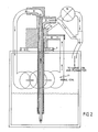
- the liquefied gas withdrawal system is generally referred to as 1.
- a representative insulated vessel, that is capable of storing a liquefied gas for an extended period of time is designated 2.
- the vessel 2 may be, for example, a dewar flask or other suitable cryogenic storage vessel.
- a heat exchanger is labelled 3.
- a withdrawal tube for withdrawing liquefied gas is labelled 6.
- Withdrawal system 1 is composed of a withdrawal tube 5 and a heat exchange 3 having two nested tubes. As shown in Fig. 1, an inner tube 5 is nested within and connected at one end to an outer tube 4, such that gas produced by vaporization of the liquefied gas from the vessel which enters the heat exchanger through outer tube 4 will exit the heat exchanger through inner tube 5.
- Withdrawal tube 6 and heat exchanger 3 can be fabricated from any heat-conductive material that is suitable for cryogenic applications, although stainless steels is the most suitable material.
- Withdrawal tube 6 and heat exchanger 3 are set within a mount 7. Mount 7 serves to maintain fixedly in place withdrawal tube 6 and heat exchanger 3, while at the same time, mount 7 serves to engage vessel 2 to form a vapor tight seal.
- Mount 7 can be fabricated from any material suitable for cryogenic applications and can have applied to its bottom a type of rubber material for facilitating making a vapor tight seal.
- Withdrawal system 1 can further include fixtures 8, 9 and 10, which attach to withdrawal tube 6, inner tube 5 and outer tube 4, respectively. Fixtures 8, 9, and 10 serve to facilitate connection of withdrawal system 1 to various devices for storing and using the withdrawal liquid and for supplying gas to heat exchanger 3.
- Fig. 1 also shows a preferred embodiment of the invention in which withdrawal tube 6 is located within and concentric with inner tube 4.
- withdrawal tube 6 is located within and concentric with inner tube 4.
- One advantage of this configuration is that the withdrawal system of Fig. 1 will fit inside insulated vessels having narrow openings.
- Fig. 2 illustrates an embodiment of the instant invention which further includes gasifying means 11, which may be a conventional heating coil or heat exchanger connected in series with inner tube 5 and outer tube 4 and withdrawal tube 6 to form a loop.
- gasifying means 11 may be a conventional heating coil or heat exchanger connected in series with inner tube 5 and outer tube 4 and withdrawal tube 6 to form a loop.
- the preferred method uses the ambient air to provide heat to the heating coil to warm the liquid to convert it to gas, which is then warmed to as close to room temperature as possible.
- the mount 7 may also be penetrated with a fixture 14, to which is connected a conventional back pressure regulator, which is also connected with fixture 9, from which gas exits the heat exchanger. Gas then exits the back pressure regulator through fixture 16, which is connected to the end use system.
- the liquified gas is indicated as 13.
- the head space in the vessel above the liquefied gas is designated 12.
- head space 12 increases in size.
- the pressure within the vessel decreases, thereby slowing the rate at which liquefied gas 13 is withdrawn.
- gas from the gasifying means 11 is circulated through heat exchanger 3 to gasify liquefied gas 13.
- the gasified liquid increases pressure within the vessel such that liquefied gas is more readily withdrawn through withdrawal tube 6.
- the heat exchanger works as follows. Heating coil 11 heats a portion of the liquid drawn through withdrawal tube 6 to a temperature sufficient to vaporize the liquid. The gas then enters the heat exchanger through fixture 10. Once inside heat exchanger 3, the gas releases its heat through the outside wall of outer tube 4, thereby partially gasifying liquefied gas 13. In the process of giving up heat, the gas cools and is then withdrawn from the heat exchanger through inner tube 5 and finally exits the heat exchanger through fixture 9.
Landscapes
- Engineering & Computer Science (AREA)
- Mechanical Engineering (AREA)
- General Engineering & Computer Science (AREA)
- Filling Or Discharging Of Gas Storage Vessels (AREA)
Applications Claiming Priority (1)
| Application Number | Priority Date | Filing Date | Title |
|---|---|---|---|
| US89056286A | 1986-07-30 | 1986-07-30 |
Publications (1)
| Publication Number | Publication Date |
|---|---|
| EP0356546A1 true EP0356546A1 (de) | 1990-03-07 |
Family
ID=25396836
Family Applications (1)
| Application Number | Title | Priority Date | Filing Date |
|---|---|---|---|
| EP88114126A Withdrawn EP0356546A1 (de) | 1986-07-30 | 1988-08-30 | Verfahren und Vorrichtung zur kryogenen Entnahme |
Country Status (1)
| Country | Link |
|---|---|
| EP (1) | EP0356546A1 (de) |
Citations (4)
| Publication number | Priority date | Publication date | Assignee | Title |
|---|---|---|---|---|
| US2964918A (en) * | 1957-03-11 | 1960-12-20 | Union Carbide Corp | Method and apparatus for dispensing gas material |
| US3696627A (en) * | 1971-01-18 | 1972-10-10 | Air Prod & Chem | Liquid cryogen transfer system |
| US4211086A (en) * | 1977-10-11 | 1980-07-08 | Beatrice Foods Company | Cryogenic breathing system |
| US4783969A (en) * | 1986-07-30 | 1988-11-15 | Penox Technologies, Inc. | Cryogenic withdrawal apparatus and method |
-
1988
- 1988-08-30 EP EP88114126A patent/EP0356546A1/de not_active Withdrawn
Patent Citations (4)
| Publication number | Priority date | Publication date | Assignee | Title |
|---|---|---|---|---|
| US2964918A (en) * | 1957-03-11 | 1960-12-20 | Union Carbide Corp | Method and apparatus for dispensing gas material |
| US3696627A (en) * | 1971-01-18 | 1972-10-10 | Air Prod & Chem | Liquid cryogen transfer system |
| US4211086A (en) * | 1977-10-11 | 1980-07-08 | Beatrice Foods Company | Cryogenic breathing system |
| US4783969A (en) * | 1986-07-30 | 1988-11-15 | Penox Technologies, Inc. | Cryogenic withdrawal apparatus and method |
Similar Documents
| Publication | Publication Date | Title |
|---|---|---|
| US6012453A (en) | Apparatus for withdrawal of liquid from a container and method | |
| US4783969A (en) | Cryogenic withdrawal apparatus and method | |
| US5438837A (en) | Apparatus for storing and delivering liquid cryogen and apparatus and process for filling same | |
| EP0131652B1 (de) | Kondensor | |
| US6089226A (en) | Self contained, cryogenic mixed gas single phase storage and delivery | |
| US3882687A (en) | Method of and apparatus for the cooling of an object | |
| EP2613109B1 (de) | Verfahren zur Aufbewahrung einer kryogenen Flüssigkeit in einem Aufbewahrungsbehälter | |
| US3030780A (en) | Refrigerated container for liquefied gases | |
| US5582016A (en) | Conditioning and loading apparatus and method for gas storage at cryogenic temperature and supercritical pressure | |
| US3201947A (en) | Cryogenic transport tube incorporating liquefaction apparatus | |
| CA1222231A (en) | Low pressure cryogenic liquid delivery system | |
| CA2614195C (en) | Cryogenic tank system | |
| US6230516B1 (en) | Apparatus for mixing a multiple constituent liquid into a container and method | |
| US3803858A (en) | Gas transfer system for liquid fuels | |
| KR102282181B1 (ko) | 직냉식 액화장치 | |
| EP0670452A1 (de) | Vorrichtung und Verfahren zum Laden, Lagern und Abgeben von Flüssigkeiten bei kryogenen Temperaturen | |
| CA1286592C (en) | Cryogenic withdrawal apparatus and method | |
| EP0356546A1 (de) | Verfahren und Vorrichtung zur kryogenen Entnahme | |
| US11649929B2 (en) | Gas dispensing system with tank pressure and heat management | |
| US3126711A (en) | E miller | |
| US6453677B1 (en) | Magnetic refrigeration cryogenic vessel system | |
| CN115605707A (zh) | 用于从储存杜瓦瓶提取冷冻剂的液相的方法 | |
| Warren | A pressurized helium II-cooled magnet test facility | |
| JPH0293199A (ja) | 低温液体回収装置及びその回収方法 | |
| US3867818A (en) | Method and apparatus for cryogenic tank warm-up |
Legal Events
| Date | Code | Title | Description |
|---|---|---|---|
| PUAI | Public reference made under article 153(3) epc to a published international application that has entered the european phase |
Free format text: ORIGINAL CODE: 0009012 |
|
| AK | Designated contracting states |
Kind code of ref document: A1 Designated state(s): AT BE CH DE FR GB IT LI LU NL SE |
|
| 17P | Request for examination filed |
Effective date: 19900807 |
|
| STAA | Information on the status of an ep patent application or granted ep patent |
Free format text: STATUS: THE APPLICATION IS DEEMED TO BE WITHDRAWN |
|
| 18D | Application deemed to be withdrawn |
Effective date: 19920303 |