EP0356576A2 - Structure de couches et un récipient comprenant une telle structure de couches - Google Patents
Structure de couches et un récipient comprenant une telle structure de couches Download PDFInfo
- Publication number
- EP0356576A2 EP0356576A2 EP88116892A EP88116892A EP0356576A2 EP 0356576 A2 EP0356576 A2 EP 0356576A2 EP 88116892 A EP88116892 A EP 88116892A EP 88116892 A EP88116892 A EP 88116892A EP 0356576 A2 EP0356576 A2 EP 0356576A2
- Authority
- EP
- European Patent Office
- Prior art keywords
- layer
- layer structure
- container
- layers
- neck portion
- Prior art date
- Legal status (The legal status is an assumption and is not a legal conclusion. Google has not performed a legal analysis and makes no representation as to the accuracy of the status listed.)
- Withdrawn
Links
Images



Classifications
-
- B—PERFORMING OPERATIONS; TRANSPORTING
- B65—CONVEYING; PACKING; STORING; HANDLING THIN OR FILAMENTARY MATERIAL
- B65D—CONTAINERS FOR STORAGE OR TRANSPORT OF ARTICLES OR MATERIALS, e.g. BAGS, BARRELS, BOTTLES, BOXES, CANS, CARTONS, CRATES, DRUMS, JARS, TANKS, HOPPERS, FORWARDING CONTAINERS; ACCESSORIES, CLOSURES, OR FITTINGS THEREFOR; PACKAGING ELEMENTS; PACKAGES
- B65D1/00—Rigid or semi-rigid containers having bodies formed in one piece, e.g. by casting metallic material, by moulding plastics, by blowing vitreous material, by throwing ceramic material, by moulding pulped fibrous material or by deep-drawing operations performed on sheet material
- B65D1/02—Bottles or similar containers with necks or like restricted apertures, designed for pouring contents
- B65D1/0223—Bottles or similar containers with necks or like restricted apertures, designed for pouring contents characterised by shape
- B65D1/0292—Foldable bottles
-
- B—PERFORMING OPERATIONS; TRANSPORTING
- B32—LAYERED PRODUCTS
- B32B—LAYERED PRODUCTS, i.e. PRODUCTS BUILT-UP OF STRATA OF FLAT OR NON-FLAT, e.g. CELLULAR OR HONEYCOMB, FORM
- B32B1/00—Layered products having a non-planar shape
-
- B—PERFORMING OPERATIONS; TRANSPORTING
- B32—LAYERED PRODUCTS
- B32B—LAYERED PRODUCTS, i.e. PRODUCTS BUILT-UP OF STRATA OF FLAT OR NON-FLAT, e.g. CELLULAR OR HONEYCOMB, FORM
- B32B27/00—Layered products comprising a layer of synthetic resin
- B32B27/06—Layered products comprising a layer of synthetic resin as the main or only constituent of a layer, which is next to another layer of the same or of a different material
- B32B27/08—Layered products comprising a layer of synthetic resin as the main or only constituent of a layer, which is next to another layer of the same or of a different material of synthetic resin
-
- B—PERFORMING OPERATIONS; TRANSPORTING
- B32—LAYERED PRODUCTS
- B32B—LAYERED PRODUCTS, i.e. PRODUCTS BUILT-UP OF STRATA OF FLAT OR NON-FLAT, e.g. CELLULAR OR HONEYCOMB, FORM
- B32B27/00—Layered products comprising a layer of synthetic resin
- B32B27/30—Layered products comprising a layer of synthetic resin comprising vinyl (co)polymers; comprising acrylic (co)polymers
- B32B27/304—Layered products comprising a layer of synthetic resin comprising vinyl (co)polymers; comprising acrylic (co)polymers comprising vinyl halide (co)polymers, e.g. PVC, PVDC, PVF, PVDF
-
- B—PERFORMING OPERATIONS; TRANSPORTING
- B32—LAYERED PRODUCTS
- B32B—LAYERED PRODUCTS, i.e. PRODUCTS BUILT-UP OF STRATA OF FLAT OR NON-FLAT, e.g. CELLULAR OR HONEYCOMB, FORM
- B32B27/00—Layered products comprising a layer of synthetic resin
- B32B27/32—Layered products comprising a layer of synthetic resin comprising polyolefins
-
- B—PERFORMING OPERATIONS; TRANSPORTING
- B32—LAYERED PRODUCTS
- B32B—LAYERED PRODUCTS, i.e. PRODUCTS BUILT-UP OF STRATA OF FLAT OR NON-FLAT, e.g. CELLULAR OR HONEYCOMB, FORM
- B32B37/00—Methods or apparatus for laminating, e.g. by curing or by ultrasonic bonding
- B32B37/14—Methods or apparatus for laminating, e.g. by curing or by ultrasonic bonding characterised by the properties of the layers
- B32B37/15—Methods or apparatus for laminating, e.g. by curing or by ultrasonic bonding characterised by the properties of the layers with at least one layer being manufactured and immediately laminated before reaching its stable state, e.g. in which a layer is extruded and laminated while in semi-molten state
- B32B37/153—Methods or apparatus for laminating, e.g. by curing or by ultrasonic bonding characterised by the properties of the layers with at least one layer being manufactured and immediately laminated before reaching its stable state, e.g. in which a layer is extruded and laminated while in semi-molten state at least one layer is extruded and immediately laminated while in semi-molten state
-
- B—PERFORMING OPERATIONS; TRANSPORTING
- B32—LAYERED PRODUCTS
- B32B—LAYERED PRODUCTS, i.e. PRODUCTS BUILT-UP OF STRATA OF FLAT OR NON-FLAT, e.g. CELLULAR OR HONEYCOMB, FORM
- B32B7/00—Layered products characterised by the relation between layers; Layered products characterised by the relative orientation of features between layers, or by the relative values of a measurable parameter between layers, i.e. products comprising layers having different physical, chemical or physicochemical properties; Layered products characterised by the interconnection of layers
- B32B7/02—Physical, chemical or physicochemical properties
- B32B7/022—Mechanical properties
-
- B—PERFORMING OPERATIONS; TRANSPORTING
- B65—CONVEYING; PACKING; STORING; HANDLING THIN OR FILAMENTARY MATERIAL
- B65D—CONTAINERS FOR STORAGE OR TRANSPORT OF ARTICLES OR MATERIALS, e.g. BAGS, BARRELS, BOTTLES, BOXES, CANS, CARTONS, CRATES, DRUMS, JARS, TANKS, HOPPERS, FORWARDING CONTAINERS; ACCESSORIES, CLOSURES, OR FITTINGS THEREFOR; PACKAGING ELEMENTS; PACKAGES
- B65D25/00—Details of other kinds or types of rigid or semi-rigid containers
- B65D25/38—Devices for discharging contents
- B65D25/40—Nozzles or spouts
- B65D25/42—Integral or attached nozzles or spouts
- B65D25/44—Telescopic or retractable nozzles or spouts
-
- B—PERFORMING OPERATIONS; TRANSPORTING
- B32—LAYERED PRODUCTS
- B32B—LAYERED PRODUCTS, i.e. PRODUCTS BUILT-UP OF STRATA OF FLAT OR NON-FLAT, e.g. CELLULAR OR HONEYCOMB, FORM
- B32B2323/00—Polyalkenes
- B32B2323/04—Polyethylene
-
- B—PERFORMING OPERATIONS; TRANSPORTING
- B32—LAYERED PRODUCTS
- B32B—LAYERED PRODUCTS, i.e. PRODUCTS BUILT-UP OF STRATA OF FLAT OR NON-FLAT, e.g. CELLULAR OR HONEYCOMB, FORM
- B32B2327/00—Polyvinylhalogenides
- B32B2327/06—PVC, i.e. polyvinylchloride
-
- B—PERFORMING OPERATIONS; TRANSPORTING
- B32—LAYERED PRODUCTS
- B32B—LAYERED PRODUCTS, i.e. PRODUCTS BUILT-UP OF STRATA OF FLAT OR NON-FLAT, e.g. CELLULAR OR HONEYCOMB, FORM
- B32B2439/00—Containers; Receptacles
Definitions
- the present invention relates to a layer structure and a container with such a layer structure.
- Layer structures made of plastic material are known since long and are frequently used in different configurations and parts of containers. According to the use of such layer structures one encounters often the need to form such a layer structure mechanically by bending or folding into a desired shape, whereby the layer structure should maintain such a shape. This is for instance the case for tubes of such layer structures as for flexible tubes in car production, flexible tubes for container spouts etc.
- the present application has the object to propose a layer structure which fulfils all three above mentioned conditions, i.e.
- the present application further proposes a container according to claim 4.
- a process to produce the inventive layer structure is defined by claim 23, preferred realizations of that process and especially directed for that process in container production are defined by the further claims 24 to 32.
- the present invention relates to a plastic container too with an integral flexible neck that can be flexed from an upright position through e.g. approximately 90°.
- the present invention further provides an integral neck of a container which is formed of two compatible coextruded plastic materials.
- Containers with integral flexible necks that can be flexed through e.g. approximately 90° are used for pouring liquids such as oil, brake fluids, anti freeze, windshield washer fluids etc. into filling apertures.
- These containers with flexible necks are generally injection blow molded or extrusion blow molded from a single plastic material, and it has been found that the flexible neck portion is invariably weak which results in cracking or breaking. This is particularly true with neck portions having accordion shaped ribs, as it is true for one layer structures with such configuration in general.
- containers or other such structured layer structures formed of high density polyethylene used for bleach or some types of detergents may have stress cracking occurring in the neck portion. This stress cracking is due to a reaction between the liquid in the container and the container material.
- the thickness of the two or more layers of material can vary depending on the need and the application of the container. In one embodiment, it is prefer onlyred to have the flexible plastic material layer less thick than the rigid plastic material layer.
- the present invention also provides a container having integral therewith a flexible neck portion with a smaller cross sectional area than the container, the neck portion comprising a plurality of shaped accordion ribs around the neck portion extending for at least a part of the length of the neck portion such that an integral pouring spout at the end of the neck portion can be flexed to a flexed position from an upright position to accommodate pouring and generally retain the flexed position, the neck portion formed of at least two compatible layers integrally bonded together, one layer formed of a substantially rigid plastic material and the other layer formed of a substantially flexible plastic material.
- the rigid material is preferably on the outside of the neck portion and may be a high density polyethylene, in which case the flexible plastic material is preferably a low density polyethylene or copolymer.
- the rigid plastic material is rigid polyvinyl chloride and the flexible material is a flexible polyvinyl chloride.
- the thicknesses of the layers may vary along the length of the neck portion and either a constant ratio may be maintained between the two layers or, alternatively, it may be varied for the length of the neck portion.
- a layer of the flexible plastic material may extend throughout the inside of the container body or may only extend for the length of the neck portion.
- An additional layer such as a barrier layer may be coextruded between the substantially rigid layer and substantially flexible layer, however, the barrier layer must be compatible with the other two layers so that they fuse together on the boundary layers.
- the present invention also provides for a process of forming the inventive layer structure or a plastic container with such structure and having integral therewith a flexible neck portion including a plurality of shaped accordion ribs around the neck portion extending for at least the length of the neck portion, wherein a parison of hot plastic material is extruded and subsequently blow molded in a mold, the improvement comprising the steps of: coextruding at least the neck portion of the parison with at least two compatible layers integrally bonded together, one layer of a substantially rigid plastic material and a second layer of substantially flexible plastic material.
- fig. 1 shows a container with an integral flexible neck 12 having a spout 14 and a plurality of shaped accordion ribs 16 ex tending for approximately half the length of the neck portion 12.
- This container which is of the known type of containers and is substantially disclosed in Patent 4,492,324, permits the spout 14 to be flexed to an angle of approximately 90° from the axis of the container 10 and also allows the container to retain the flexed shape so that the contents of the container can be poured into a receptacle or access opening which may be difficult to reach.
- the containers similar to that shown in fig. 1, are made of high density polyethylene or rigid polyvinylchloride as this material does permit the neck to be flexed and retain its shape after the flexing step.
- Figs. 2 and 3 illustrate an extruded parison 20 which in the top or neck portion 22 as shown in fig. 2 has two layers, an outside layer 24 which is of the same plastic material as the remainder of the parison that is formed into the container and an inside layer 26 which in this embodiment extends only for the neck portion.
- the outer layer of plastic material 22 is a rigid plastic material with the inner layer being a flexible plastic material coextruded in the parison.
- the two plastic materials readily fuse together on the boundary layer so they become integrally bound together. In the parison state, both materials are hot and in a plastic state the parison is then transferred to a mold and blown from within the parison to take up the shape of the mold.
- Fig. 3 illustrates one embodiment of a parison wherein the outer layer 24 represents approximately 90% of the overall thickness of the parison, the inner layer 26 representing the other 10%. It has been found that the flexible inner layer 26 may be less than 10% of the thickness of the parison, in some cases as low as 3%, and hence the neck portion of the molded container.
- the flexible inner layer 26 has the effect of an inner tube in a pneumatic tire and provides break and tear resistance for the container.
- the inner layer 26 also reduces stress cracking on the container when used with liquids such as some detergents and bleaches which react with some rigid plastic materials.
- Fig. 4 illustrates a parison with an inner layer 26 and outer layer 24 having substantially the same thickness throughout the length of the neck portion.
- Fig. 5 illustrates the neck portion blow molded in a mold 30, the accordion ribs have a substantially horizontal wall 32 which extends out from an inner corner 34 to an outer corner 36 in the form of a saw tooth.
- a tapered wall 38 extends from the outer corner down to the lower inner corner 34.
- Fig. 5 illustrates a neck portion which has substantially the same thickness of inner layer and outer layer.
- Figs. 6 and 7 illustrate another embodiment wherein the parison 20 has a varying thickness along its length which when expanded into a mold 30, produces an increased thickness in the tapered wall 38.
- the inner layer 26 has substantially the same thickness throughout the neck portion and it is the rigid or inner layer 24 which varies in thickness.
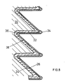
- Fig. 8 illustrates another embodiment of a neck portion expanded in a mold 30 wherein the outer layer 24 has substantially the same thickness throughout the length of the neck portion, but the inner layer 26 has increased thickness at the outside corners 36 and the inside corners 34. Further additionally, Fig. 8 illustrates a barrier layer 40 which is coextruded with the outer layer 24 and the inner layer 34.
- the barrier layer is of compatible plastic material integrally bonded between the two layers and fused readily between the two layers so that it cannot separate.
- Variation of the thickness for the outer layer 24 and the inner layer 26 is achieved by programming the flow of molten plastic material delivered to the extruder head.
- One type of programmer has 99 points wherein the flow rate for either the inner layer 26 or outer layer 24 can be changed.
- the thickness of the neck portion can be made so that the ratio of the inner layer 26 to the outer layer 20 is always constant or, alternatively, so that the ratio varies to suit the particular configuration of neck portion thus some corners or some walls may have increased thicknesses, either for the inner layer or for the outer layer or for both.
- the rigid layer be the outside layer of the neck portion 24, however, in certain circumstances, the flexible layer may be placed on the outside.
- fig. 2 shows the parison 20 only having the inner layer 26 extending for the neck portion.
- the inner layer may extend for the complete length of the parison so that when a container is blown in a mold it is completely lined with a separate plastic material which may be a flexible plastic material.
- the liner in the container may be considerably thinner than the inner layer of the neck portion.
- High density polyethylene is a suitable material for forming a container with an integral flexible neck portion formed therewith.
- the inner layer is preferably a low density polyethylene or a special copolymer that is flexible and fuses readily on the boundary layer with high density polyethylene.
- a rigid polyvinylchloride represents one layer and a flexible polyvinylchloride forms the flexible layer which is integrally extruded into a parison.
- Polypropylene and polypropylene copolymers may be used as well as rigid and flexible nylon material.
- a container for oil was produced with a high density polyethylene as an outside layer and a low density polyethylene copolymer as an inside layer.
- the extruded parison had the outside layer approximately 90% of the wall thickness which was .060 ⁇ . This wall thickness was reduced by about half when the container was blown in the blowing station, but the ratio of outside layer to inside layer remained about the same. Tests showed that the neck portion stood up to one thousand flexings to the maximum position of 90° from the axis of the container without any visible deterioration or delamination of the two separate layers.
- the invention i.e. the two layer structure and the process for its manufacturing by coextrusion, has been described for one preferred example, namely that of container spout application.
- the inventive two layer structure concept may be used for many other applications, as for car manufacturing application as will be described now.
- a structure of plastic material is made of one layer 50.
- this layer 50 shall be formed into a predetermined structure as shall be bent to form a corner 52 and then shall maintain this structure, for instance with the corner 52, the one layer structure is made of a relatively rigid plastic material.
- the structure 50 After the structure 50 has been formed into the desired structure, e.g. with corner 52, it is loaded by frequent changes of its structure, e.g. the corner 52 is flexed and deflexed into a sharper configuration 52a and back to the previous configuration 52 as shown by the vice-versa arrow A.
- Such a loading may occur by mechanical vibration, even at high frequencies, or by manual loading if the preselected structure or form is changed during time.
- the time varying loading represented by the arrow A results especially because the one layer 50 has to be made of relatively rigid material to maintain its shape, and as shown at the right hand side of fig. 9a in cracking of the layer 50 first at those parts which are most loaded by the deformations in time.
- cracks 54 will occur first at the outer surface which then will propagate through the entire structure of the layer 50 up to the moment reaching the interior surface.
- the inventive layer structure comprises a first layer 60 and a second layer 62 as was disclosed previously in connection with the container use.
- the preferably thicker layer 60 is made as the layer 50 in known structures of relatively rigid plastic material to fulfil the requirements of self holding form-stability.
- the thinner layer 62 of the inventive layer structure processed, as was disclosed in connection with the use for containers, is made of the said flexible material.
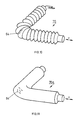
- FIG. 10 there is shown an accordion structure tube 70, as it is used, for instance, in car manufacturing as for air pipes.
- the inventive layer structure according to fig. 9b for such a pipe 70 lifetime of such pipes loaded by mechanical vibrations v is considerably improved.
- Additionally it becomes possible to preform such tube 70 just before mounting which makes this mounting easier compared with the mounting of such accordion structure tubes which are not self holding in a shape to which they just have been brought.
- Additionally much less care and less expensive material may be used for such tubes as now tightness is ensured by a thin layer as layer 62 of fig.
Landscapes
- Engineering & Computer Science (AREA)
- Mechanical Engineering (AREA)
- Ceramic Engineering (AREA)
- Laminated Bodies (AREA)
- Cultivation Receptacles Or Flower-Pots, Or Pots For Seedlings (AREA)
- Bag Frames (AREA)
- Blow-Moulding Or Thermoforming Of Plastics Or The Like (AREA)
Applications Claiming Priority (2)
| Application Number | Priority Date | Filing Date | Title |
|---|---|---|---|
| US23819888A | 1988-08-30 | 1988-08-30 | |
| US238198 | 1988-08-30 |
Publications (2)
| Publication Number | Publication Date |
|---|---|
| EP0356576A2 true EP0356576A2 (fr) | 1990-03-07 |
| EP0356576A3 EP0356576A3 (fr) | 1991-01-30 |
Family
ID=22896890
Family Applications (1)
| Application Number | Title | Priority Date | Filing Date |
|---|---|---|---|
| EP19880116892 Withdrawn EP0356576A3 (fr) | 1988-08-30 | 1988-10-12 | Structure de couches et un récipient comprenant une telle structure de couches |
Country Status (1)
| Country | Link |
|---|---|
| EP (1) | EP0356576A3 (fr) |
Cited By (2)
| Publication number | Priority date | Publication date | Assignee | Title |
|---|---|---|---|---|
| WO1995024347A1 (fr) * | 1994-03-10 | 1995-09-14 | Dowbrands Inc. | Recipient pliable, utilisable dans un four a micro-ondes |
| WO2004110878A1 (fr) * | 2003-06-12 | 2004-12-23 | Concordia Development S.R.L. | Recipient jetable ameliore, progressivement repliable |
Family Cites Families (6)
| Publication number | Priority date | Publication date | Assignee | Title |
|---|---|---|---|---|
| GB636965A (en) * | 1946-10-19 | 1950-05-10 | Us Rubber Co | Improvements in laminar structures |
| FR1359348A (fr) * | 1963-03-15 | 1964-04-24 | Récipient | |
| BE662854A (fr) * | 1965-04-21 | 1965-08-17 | ||
| US4526296A (en) * | 1981-12-07 | 1985-07-02 | Berger Richard F | Flexible pleated container structure |
| US4492324A (en) * | 1982-03-15 | 1985-01-08 | Heinz Weber | Container with integral flexible neck |
| CA1335253C (fr) * | 1986-03-17 | 1995-04-18 | Keiji Sugimoto | Pellicule et emballage multicouche en plastique |
-
1988
- 1988-10-12 EP EP19880116892 patent/EP0356576A3/fr not_active Withdrawn
Cited By (2)
| Publication number | Priority date | Publication date | Assignee | Title |
|---|---|---|---|---|
| WO1995024347A1 (fr) * | 1994-03-10 | 1995-09-14 | Dowbrands Inc. | Recipient pliable, utilisable dans un four a micro-ondes |
| WO2004110878A1 (fr) * | 2003-06-12 | 2004-12-23 | Concordia Development S.R.L. | Recipient jetable ameliore, progressivement repliable |
Also Published As
| Publication number | Publication date |
|---|---|
| EP0356576A3 (fr) | 1991-01-30 |
Similar Documents
| Publication | Publication Date | Title |
|---|---|---|
| US8191568B2 (en) | Fuel tank for motor vehicle | |
| US6508275B1 (en) | Flexible fuel filler pipe | |
| CN1065986C (zh) | 波纹管和用管子作为套的导线束 | |
| US7562679B2 (en) | Resin pipe and resin molded component | |
| AU724022B2 (en) | Extrusion blow molded container having cylindrical drum portion and mold for shaping the container | |
| US4526296A (en) | Flexible pleated container structure | |
| CN103210233B (zh) | 保护罩及其制造方法 | |
| EP2468642B1 (fr) | Récipient moulé par soufflage | |
| US20020017331A1 (en) | Variable stiffness bellows | |
| KR970704609A (ko) | 다층 용기(Multi-Layer Containers) | |
| EP1156253B1 (fr) | Tube annele a base de resine | |
| CN1240382A (zh) | 具有膨胀内壁的多腔室容器 | |
| US4464980A (en) | Bellows actuator | |
| EP1099641A1 (fr) | Contenant en resine synthetique portant une etiquette | |
| EP0356576A2 (fr) | Structure de couches et un récipient comprenant une telle structure de couches | |
| CN102802993A (zh) | 树脂燃料箱 | |
| US20080231046A1 (en) | Bellows-shaped hollow body | |
| JP4240221B2 (ja) | 多層溶融樹脂塊 | |
| EP0641719B1 (fr) | Bouteille de resine synthetique | |
| CN112976699A (zh) | 波纹管、波纹管的应用和用于制造波纹管的方法 | |
| KR920000004B1 (ko) | 다층 합성수지제 캔 몸체 및 그 제조방법 | |
| JP2009113704A (ja) | 熱可塑性合成樹脂製の燃料タンク | |
| US7600652B1 (en) | Multiple layer polymeric cap and method of making the same | |
| WO2007025251A2 (fr) | Recipient en matiere plastique presentant un renfort de forme annulaire, et procede de fabrication de ce recipient | |
| US20240076092A1 (en) | Extrusion blow-molded container |
Legal Events
| Date | Code | Title | Description |
|---|---|---|---|
| PUAI | Public reference made under article 153(3) epc to a published international application that has entered the european phase |
Free format text: ORIGINAL CODE: 0009012 |
|
| AK | Designated contracting states |
Kind code of ref document: A2 Designated state(s): AT BE CH DE ES FR GB GR IT LI LU NL SE |
|
| PUAL | Search report despatched |
Free format text: ORIGINAL CODE: 0009013 |
|
| AK | Designated contracting states |
Kind code of ref document: A3 Designated state(s): AT BE CH DE ES FR GB GR IT LI LU NL SE |
|
| 18D | Application deemed to be withdrawn |
Effective date: 19910503 |