EP0356620A1 - Automatische Steuerung der Fokussierung einer Video-Kamera für industrielle/militärische Zwecke - Google Patents
Automatische Steuerung der Fokussierung einer Video-Kamera für industrielle/militärische Zwecke Download PDFInfo
- Publication number
- EP0356620A1 EP0356620A1 EP89109199A EP89109199A EP0356620A1 EP 0356620 A1 EP0356620 A1 EP 0356620A1 EP 89109199 A EP89109199 A EP 89109199A EP 89109199 A EP89109199 A EP 89109199A EP 0356620 A1 EP0356620 A1 EP 0356620A1
- Authority
- EP
- European Patent Office
- Prior art keywords
- image
- frame
- focusing
- video camera
- screen
- Prior art date
- Legal status (The legal status is an assumption and is not a legal conclusion. Google has not performed a legal analysis and makes no representation as to the accuracy of the status listed.)
- Granted
Links
Images


Classifications
-
- B—PERFORMING OPERATIONS; TRANSPORTING
- B25—HAND TOOLS; PORTABLE POWER-DRIVEN TOOLS; MANIPULATORS
- B25J—MANIPULATORS; CHAMBERS PROVIDED WITH MANIPULATION DEVICES
- B25J9/00—Program-controlled manipulators
- B25J9/16—Program controls
- B25J9/1694—Program controls characterised by use of sensors other than normal servo-feedback from position, speed or acceleration sensors, perception control, multi-sensor controlled systems, sensor fusion
- B25J9/1697—Vision controlled systems
-
- H—ELECTRICITY
- H04—ELECTRIC COMMUNICATION TECHNIQUE
- H04N—PICTORIAL COMMUNICATION, e.g. TELEVISION
- H04N23/00—Cameras or camera modules comprising electronic image sensors; Control thereof
- H04N23/60—Control of cameras or camera modules
- H04N23/67—Focus control based on electronic image sensor signals
- H04N23/673—Focus control based on electronic image sensor signals based on contrast or high frequency components of image signals, e.g. hill climbing method
-
- H—ELECTRICITY
- H04—ELECTRIC COMMUNICATION TECHNIQUE
- H04N—PICTORIAL COMMUNICATION, e.g. TELEVISION
- H04N23/00—Cameras or camera modules comprising electronic image sensors; Control thereof
- H04N23/60—Control of cameras or camera modules
- H04N23/695—Control of camera direction for changing a field of view, e.g. pan, tilt or based on tracking of objects
Definitions
- the invention lies in the fields of optics, electronics and image processing technology. It relates to a device according to the preamble of claim 1 and a method for automatically optimizing the focusing of a video image, which is used to control a manipulation device.
- the video camera is used to supply an industrial robot, or the image of a FLIR camera is used to supply the image control unit (so-called video tracker) of an automatic target tracking device.
- FLIR forward looking infrared
- the camera sends out a signal, for example an ultrasound or infrared beam, and receives the signal reflected by the object.
- a signal for example an ultrasound or infrared beam
- the distance between the object and the camera can be determined from the time difference between the emitted signal and the echo.
- the reflected signal is from the side of the transmitter on the camera wide determined.
- the focus setting is finally made on the basis of the functional relationship between object width and image width.
- the information about the focusing state is taken directly from the received image based on a defined criterion.
- the lens setting is corrected until an optimum that corresponds to the focusing criterion is reached.
- the focus in photo cameras is therefore often based on other criteria.
- the image section to be focused is imaged by two lenses on a CCD image sensor chain.
- the position of the focus with respect to the image plane is inferred from the distance between the image structures corresponding to the two lenses. Detailed information can be found in the data sheets of relevant photo cameras.
- a CCD image analysis method such as the one already mentioned, is very often used because the active methods (ultrasound and infrared methods) are not given enough reliability.
- the interference of infrared reflection by glass panes and sloping object surfaces should be mentioned.
- the object is achieved by the invention according to patent claims 1 and 11. This is a procedure that uses an automatic, passive focusing based on real-time image evaluation, which is based on the fact that the mean value of the light intensity is measured in a limited, predetermined image field and the intensity extremum is sought as a function of the focus setting.
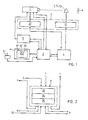
- Fig. 1 shows the basic structure of a device for applying the inventive method using a block diagram. It is a device for optical monitoring of an automatically controllable manipulation device 2, for example an industrial robot 21 or a fully automatically controllable machine tool. The gripping and handling of the object 7, for example a workpiece 71 or a tool 72, is monitored by means of a video camera 1.
- an automatically controllable manipulation device 2 for example an industrial robot 21 or a fully automatically controllable machine tool.
- the gripping and handling of the object 7, for example a workpiece 71 or a tool 72 is monitored by means of a video camera 1.
- the device essentially consists of a video camera 1 which receives the image of the object 7 and an image control unit which transmits electrical analog signals corresponding to the image information.
- the image information is evaluated in this image control unit, signals for optimal operation of the video camera 1 being fed back to the latter directly or indirectly via the focus control 5.
- the processed image information of the image control unit 3 is received by the main computer 4 and transformed there into control signals. These are converted into a sequence of movements of the controllable manipulation device 2, for example via a servo system.
- the main computer 4 additionally controls the entire movement of the device, for example also a platform 22, which is in a mechanically rigid connection with the video camera 1 and thus allows the video camera 1 to track the object 7.
- the monitor 6, which is connected to the image control unit 3, permits visual monitoring of the object 7.
- the manipulator 31, which is also connected to the image control unit 3, allows the object 7 to be assigned manually.
- the image control unit 3, the focus control 5 and the main computer 4 can, for example, be combined to form a unit.
- the basic structure of the image control unit 3 is shown in FIG. 2. It consists of the image evaluation unit 33, the object brightness control unit 34 and the I / O processor 35.
- the analog video signal of video camera 1 is first digitized by an A / D converter, i.e. transformed into number sequences, which provide information about the intensity of the individual pixels. This digital image information is then fed to the image evaluation unit 33. The interpretation of the digitized video signal is carried out there. At the most, on the basis of a so-called gray value histogram analysis, object 7 and background 8 are distinguished and signals about their brightness are fed to the object brightness control unit 34. From this, as described in another, parallel patent application with the number in detail, this generates control signals which control the video camera 1 via the I / O processor 35 in such a way that the object 7 with respect to its background 8 is shown in the illustration Brightness is highlighted as well as possible.
- the present inventive idea is based on the use of the average brightness 13 of a partial area of the video image 61 as a measure of the state of the focus of the video camera 1 on the object 7.
- This partial area is characterized by a, including the image 62 of the object 7, Frame 63 defined.
- the frame 63 is fixed, for example, by the operator using the manipulator 31 in the form of a control stick, the operator being able to determine both the position of this frame 63 and its size.
- the operator's task is to fix the frame 63 as small as possible, but enclosing the entire object image 62.
- the image control unit 3 In addition to the manual determination of the frame 63, there is also the possibility that it is automatically determined by the image control unit 3, the task of which is to recognize and optimally display the object 7 anyway.
- the average brightness 13 results from the averaging of the brightness of the object pixels which lie within the frame 63.
- the focusing principle which is based on an optimization of the average brightness 13 of the object pixels 64 within the frame 63, can be seen from FIG. 3.
- the brightness distribution 11 of the object does not stand out from the brightness distribution 12 of the background, since the image 62 of the object 7 is not exactly limited due to the image blur and thus the light intensity of the object pixels 64 the surroundings of the object image 62 are transmitted.
- the light intensity of the object 7 is concentrated on the pixels 64 within the sharply defined object contour.
- the focusing process described is implemented using a digital method. In principle, however, it is also conceivable that this problem, and possibly also the image brightness control, is not carried out digitally, but takes place directly by processing the analog signals of the video camera 1. This possibility could be advantageous if the automatic focusing is integrated in the video camera.
- the object 7 stands out from the background 8 as well as possible by selecting the brightness and the image contrast (gain / offset control of the video camera 1) even before the focusing process begins.
- the image of object 7 and background 8 is not optimally adapted to the eye of the surgeon viewing the screen 61 of the monitor 6, but rather is optimized for the automatic recognition of the object 7. No manipulation should be carried out on the gain / offset control of the camera during the focusing process itself, since otherwise interference can occur between the two control systems, namely the focus and the gain / offset control.
- the command generator 53 produces periodically varying input data which takes into account the movement of the target. The presence of this data is checked in test point 54. In the negative case, the focusing cycle is exited again. Otherwise it is checked in test point 55 whether the direction of focus adjustment leading to better focusing has already been determined. Meets if this is not yet the case, the direction determiner 57 uses a small change in the focusing data to investigate whether the data supplied by the command generator leads to an improvement in the focusing in the sense of the focusing criterion discussed. If this is actually the case, the focusing cycle is exited directly, otherwise the command generator data are modified accordingly.
- test point 55 can be passed directly in the next pass.
- test point 56 it is checked whether the focus has changed significantly compared to that of the previous cycle, that is to say by a value that lies outside a predetermined limit value. If this is not the case, the focusing process is terminated by a corresponding message from the focus stop 59. Otherwise the focus cycle is exited directly.
- the image evaluation unit 33 provides the I / O processor 35 with information about the position of the object within the image area of the video camera 1. This information is fed to the main computer 4, which uses this position information to determine the movements of the industry -Roboters 21 checked. In addition, it may prove necessary to track the video camera 1 to the object 7. For this purpose, the platform 22 on which the video camera 1 is attached is controlled by control signals from the main computer 4.
- FIG. 5 shows the application of the method to a tracking device.
- the same consists of an azimuthal and inclinable platform 22, which is in a mechanically rigid connection with the video camera 1, for example a FLIR camera, and the image control unit 3 discussed.
- the latter controls the camera 1 as well as with reference of the host computer 4, the position of the platform 22 based on the video signal generated in the tracking camera 1.
- the monitor 6, which is connected to the image control unit 3, allows the operator to visually track the target.
Landscapes
- Engineering & Computer Science (AREA)
- Multimedia (AREA)
- Signal Processing (AREA)
- Robotics (AREA)
- Mechanical Engineering (AREA)
- Automatic Focus Adjustment (AREA)
- Image Input (AREA)
- Manipulator (AREA)
- Image Processing (AREA)
Abstract
Description
- Die Erfindung liegt auf den Gebieten der Optik, der Elektronik und der Bildverarbeitungstechnik. Sie betrifft eine Vorrichtung gemäss Oberbegriff des Patentanspruchs 1 und ein Verfahren zur automatischen Optimierung der Fokussierung eines Videobildes, das zur Steuerung einer Manipulier-Vorrichtung verwendet wird. Insbesondere wird die Video-Kamera zur Versorgung eines Industrie-Roboters verwendet, oder es dient das Bild einer FLIR-Kamera zur Versorgung der Bild-Steuereinheit (sog. Video-Tracker) einer automatischen Zielverfolgungsvorrichtung. Als FLIR-Kamera (FLIR = forward looking infrared) wird eine auf Wärmestrahlung empfindliche Infrarot-Kamera bezeichnet.
- Automatische Vorrichtungen zur Scharfeinstellung (Fokussierung) des Bildes bei Kameras sind wohlbekannt. Zu unterscheiden sind aktive und passive Fokussier-Methoden.
- Bei einer ersten Methode wird von der Kamera ein Signal, beispielsweise ein Ultraschall- oder Infrarotstrahlenbündel, ausgesandt und das vom Objekt reflektierte Signal empfangen. Bei der Ultraschall-Anwendung lässt sich aus der Zeitdifferenz zwischen dem emittierten Signal und dem Echo der Abstand des Objektes von der Kamera (Objektweite) ermitteln. Bei der Infrarot-Messung wird das reflektierte Signal von einer seitlich des Senders an der Kamera weite bestimmt. Die Fokusseinstellung wird schliesslich anhand des funktionellen Zusammenhanges zwischen Objektweite und Bildweite vorgenommen. Dieses Verfahren der aktiven Distanzmessung ist für den nicht-professionellen Bereich gut geeignet und lässt sich mit beschränktem apparativen Aufwand realisieren. Bei industriellen Anwendungen dürfte die Störbarkeit des Reflexes durch andere interferierende Quellen Probleme schaffen. Im militärischen Bereich ist jegliche aktive Zielvermessung aus tarntechnischen Gründen zum vorneherein abzulehnen.
- Bei einer zweiten Methode wird die Information über den Fokussierung-Zustand direkt dem empfangenen Bild aufgrund eines festgelegten Kriteriums entnommen. Die Objektiv-Einstellung wird bis zur Erreichung eines, dem Fokussier-Kriterium entsprechenden, Optimums korrigiert.
- Vom Standpunkt der optischen Abbildungstheorie wäre es naheliegend, das Fokussier-Kriterium auf eine sog. Raumfrequenz-Analyse abzustützen. Letztere beruht auf der Eigenschaft von Sammellinsen, ein mit monochromatischer, paralleler (zeitlich und räumlich kohärent) Strahlung beleuchtetes Bild in die Fourier-Transformierte überzuführen. Diese Fourier-Transformierte, das sog. Raumfrequenz-Bild, ist in der Fokalebene der Abbildungslinse positioniert und entspricht einer Analyse der beleuchteten Bildstruktur. Grobe Strukturen des Originals bedeuten niedrige und Feinstrukturen hohe Raumfrequenzen. Letztere sind nur bei guter Fokussierung vorhanden, da Feinstrukturen nur bei scharfer Abbildung wiedergegeben werden. Das Auftreten hoher Raumfrequenzen ist somit ein brauchbares Kriterium für eine optimale Fokus-Einstellung des Objektivs. In der Praxis stösst man allerdings bei der Anwendung eines solchen Verfahrens auf Schwierigkeiten, da einerseits das Objekt fast durchwegs mit weissem - also nicht-monochromatischem - Licht bestrahlt wird und demzufolge eine Durchmischung höherer Raumfrequenzen stattfindet, andererseits die Ausmessung der Lichtintensitätsverteilung in der Fokalebene mit sehr hohe Präzision durchgeführt werden müsste.
- Die Fokussierung bei Photokameras wird daher oft nach anderen Kriterien vorgenommen. Beispielsweise wird der scharf einzustellende Bildausschnitt durch zwei Linsen auf eine CCD-Bildsensor-Kette abgebildet. Aus dem Abstand der, den beiden Linsen entsprechenden, Bildstrukturen wird auf die Lage des Fokus bezüglich der Bildebene geschlossen. Detaillierte Informationen können den Datenblättern von einschlägigen Photokameras entnommen werden.
- Bei Kameras mit elektronischer Bildaufzeichnung, beispielsweise Video-Kameras, kommen sehr oft ein CCD-Bildanalyse-Verfahren, wie das bereits erwähnte, zum Einsatz, da den aktiven Methoden (Ultraschall- und Infrarot-Verfahren) zu wenig Zuverlässigkeit beigemessen wird. Insbesondere ist die Störbarkeit der Infrarot-Reflexion durch Glasscheiben und schräge Objekt-Flächen zu erwähnen.
- Automatische Fokussier-Vorrichtungen von Kameras für nicht-industrielle Anwendungen sind vornehmlich im Sinne der Hebung des Anwender-Komfortes als Handhabungs-Erleichterungen anzusehen, im übrigen kann ihnen aber kaum eine zwingende Bedeutung beigemessen werden. Anders ist die Situation bei Kameras, die im industriellen Bereich, beispielsweise in der Robotik oder für militarische Zwekke, eingesetzt sind. In jenen Fällen können dem Operateur oft Aufwendungen für die Fokussierung schlechthin nicht zugemutet werden - einerseits weil andere Aufgaben Priorität haben, andererseits weil ihm im Falle von rasch beweglichen Objekten keine Zeit zur Nachführung der Fokussierung zur Verfügung steht. Anstrengungen zur Automatisierung des Fokussier-Vorganges sind daher mehr als angebracht. Trotzdem waren bisher keine Vorrichtungen und Verfahren zur voll befriedigenden Lösung dieses Problems bekannt.
- Eine wichtige Voraussetzung jedes Fokussier-Verfahrens ist die Erkennung des scharf einzustellenden Objektes vor dem als unscharf eingestellt hingenommenen Hintergrund. Dieses Problem ist bei nicht-industriellen oder nicht-militärischen Anwendungen bedeutungslos, da dort der zu fokussierende Bildbereich mittels einer Suchvorrichtung vom Operateur bestimmt wird.
- Es ist durchaus denkbar, dass im Video-Kamera-Bild eines Industrie-Roboters das bewegliche Objekt, beispielsweise ein Werkstück oder ein Werkzeug, gegenüber des Hintergrundes zeitweise kaum oder überhaupt nicht erkannt werden kann. Dieses Problem stellt sich insbesondere bei militärischen Zielen, die sich vor einem sich stets ändernden Hintergrund bewegen. In jenen Fällen muss der Objekt-Erkennung grosse Bedeutung beigemessen werden. Darauf soll aber hier nicht im Detail eingegangen werden, da die Helligkeits- und Kontrasts-Optimierung des Video-Bildes Gegenstand einer anderen Patentanmeldung sind.
- Es ist Aufgabe der Erfindung, ein Verfahren und eine entsprechende Vorrichtung zu schaffen, welche bei einer Video-Kamera, beispielsweise im Zusammenhang mit der Steuerung eines Industrie-Roboters, oder der Verfolgung eines Zieles mittels einer Zielverfolgungs-Plattform, ein stets optimal scharfes Bild des Objektes schafft. Die Aufgabe wird durch die Erfindung gemäss den Patentansprüchen 1 und 11 gelöst. Es ist dies ein Vorgehen das eine automatische, auf einer Echtzeit-Bildauswertung beruhenden, passiven Fokussierung benützt, die darauf beruht, dass in einem beschränkten, vorgegebenen Bildfeld der Mittelwert der Lichtintensität gemessen und das Intensitäts-Extremum in Funktion der Fokus-Einstellung gesucht wird.
- Der Aufbau der Vorrichtung wird anhand der folgenden Abbildungen beschrieben:
- Fig. 1 zeigt das Blockschema einer das erfinderische Verfahren ausführende Vorrichtung am Beispiel eines Industrie-Roboters, bestehend aus einer Video-Kamera, einer Bild-Auswerte-Einheit und einer Fokus-Steuervorrichtung,
- Fig. 2 stellt ein Blockschema der automatischen Bild-Steuereinheit dar,
- Fig. 3 veranschaulicht die Helligkeitsverteilung längs einer Koordinate auf der Bildfläche vor (Fig. 3a) und nach (Fig. 3b) der Fokussierung auf ein Objekt,
- Fig. 4 zeigt ein Blockdiagramm des Informationsflusses der automatischen Fokus-Steuervorrichtung der Video-Kamera.
- Fig. 5 zeigt das Blockschema einer Vorrichtung zur Anwendung des erfinderischen Verfahrens zur Verfolgung eines militäri-schen Zieles.
- Fig. 1 zeigt den prinzipiellen Aufbau einer Vorrichtung zur Anwendung des erfinderischen Verfahrens anhand eines Blockschemas. Es handelt sich um ein Gerät zur optischen Ueberwachung einer automatisch steuerbaren Manipulier-Vorrichtung 2, beispielsweise eines Industrie-Roboters 21 oder einer vollautomatisch steuerbaren Werkzeugmaschine. Ueberwacht wird das Ergreifen und die Handhabung des Objektes 7, beispielsweise eines Werkstückes 71 oder eines Werkzeuges 72, mittels einer Video-Kamera 1.
- Die Vorrichtung besteht im wesentlichen aus einer einer Video-Kamera 1, welche das Bild des Objektes 7 empfängt und einer Bild-Steuereinheit, die der Bildinformation entsprechende, elektrische Analogsignale überträgt. In dieser Bild-Steuereinheit wird die Bild-information ausgewertet, wobei Signale zum optimalen Betrieb der Video-Kamera 1 an letztere direkt, oder indirekt über die Fokussteuerung 5, zurückgeführt werden. Die aufbereitete Bildinformation der Bild-Steuereinheit 3 wird vom Hauptrechner 4 empfangen und dort in Steuersignale transformiert. Diese werden beispielsweise über ein Servo-System in eine Bewegungsfolge der steuerbaren Manipulier-Vorrichtung 2 umgesetzt. Der Hauptrechner 4 steuert zusätzlich den gesamten Bewegungslauf der Vorrichtung, beispielsweise auch eine Plattform 22, die mit der Video-Kamera 1 in mechanisch starrer Verbindung steht und es damit erlaubt, die Video-Kamera 1 dem Objekt 7 nachzuführen.
- Der Monitor 6, der mit der Bild-Steuereinheit 3 in Verbindung steht, gestattet eine visuelle Ueberwachung des Objektes 7. Zusätzlich erlaubt der Manipulator 31, der ebenfalls mit der Bild-Steuereinheit 3 verbunden ist, eine manuelle Zuweisung des Objektes 7.
- Die Bild-Steuereinheit 3, die Fokus-Steuerung 5 und der Hauptrechner 4 können bspw. zu einer Einheit zusammengefügt sein.
- Der prinzipielle Aufbau der Bild-Steuereinheit 3 ist in Fig. 2 dargestellt. Dieselbe besteht aus der Bildauswerte-Einheit 33, der Objekthelligkeits-Steuereinheit 34 und dem I/O-Prozessor 35.
- Das analoge Video-Signal der Video-Kamera 1 wird zunächst von einem A/D-Wandler digitalisiert, d.h. in Zahlensequenzen verwandelt, welche über die Intensität der einzelnen Bildpunkte Auskunft geben. Diese digitale Bildinformation wird anschliessend der Bild-auswerte-Einheit 33 zugeführt. Dort wird die Interpretation des digitalisierten Video-Signales vorgenommen. Allenfalls aufgrund einer sog. Grauwert-Histogramm-Analyse werden Objekt 7 und Hintergrund 8 unterschieden und Signale über deren Helligkeit der Objekthelligkeits-Steuereinheit 34 zugeführt. Diese erzeugt daraus, wie in einer anderen, parallelen Patentanmeldung mit der Nummer im Detail beschrieben ist, Steuersignale, welche über den I/O-Prozessor 35 die Video-Kamera 1 derart ansteuern, dass in der Abbildung das Objekt 7 vom Hintergrund 8 bezüglich seiner Helligkeit möglichst gut abgehoben ist.
- Die Scharfeinstellung der Video-Kamera 1, die Gegenstand der vorliegenden Erfindung ist, wird in der Fokus-Steuereinheit 5 vorgenommen. Es soll darauf anhand der Uebersichts-Darstellung von Fig. 1 und der örtlichen Bild-Helligkeitsverteilung von Fig. 3 eingegangen werden.
- Wie bereits erwähnt, kommt bei der vorgesehene Anwendung für die Scharfeinstellung der Video-Kamera 1 nur ein passives Fokussierverfahren in Frage.
- Die vorliegende erfinderische Idee beruht auf der Verwendung der mittleren Helligkeit 13 eines Teilbereiches des Video-Bildes 61 als Mass für den Zustand der Fokussierung der Video-Kamera 1 auf das Objekt 7. Dieser Teilbereich ist durch einen, das Bild 62 des Objektes 7 einschliessenden, Rahmen 63 definiert.
- Der Rahmen 63 wird beispielsweise vom Operateur mittels des Manipulators 31 in Form eines Steuerknüppels festgelegt, wobei der Operateur sowohl die Position dieses Rahmens 63, als auch dessen Grösse bestimmen kann. Die Aufgabe des Operateurs besteht darin, den Rahmen 63 möglichst klein, aber das ganze Objektbild 62 umschliessend, festzulegen. Nebst der manuellen Bestimmung des Rahmens 63 besteht auch die Möglichkeit, dass derselbe durch die Bild-Steuereinheit 3, dessen Aufgabe ohnehin in der Erkennung und optimalen Darstellung des Objektes 7 besteht, automatisch ermittelt wird.
- Die mittlere Helligkeit 13 resultiert aus der Ausmittelung der Helligkeit der Objekt-Bildpunkte, die innerhalb des Rahmens 63 liegen.
- Das Fokussier-Prinzip, das auf einer Optimierung der mittleren Helligkeit 13 der Objekt-Bildpunkte 64 innerhalb des Rahmens 63 beruht, ist anhand von Fig. 3 ersichtlich. Bei schlechter Fokussierung hebt sich, wie aus Fig. 3a hervorgeht, die Helligkeitsverteilung 11 des Objektes von der Helligkeitsverteilung 12 des Hintergrundes wenig ab, da das Bild 62 des Objektes 7 wegen der Abbildungsunschärfe nicht genau begrenzt ist und damit Lichtintensität der Objekt-Bildpunkte 64 auf die Umgebung des Objekt-Bildes 62 übertragen wird. Bei guter Fokussierung ist hingegen, wie Fig.3b zeigt, die Lichtintensität des Objektes 7 auf die Bildpunkte 64 innerhalb der scharf begrengten Objektkontur konzentriert. Die mittlere Helligkeit 13, welche diesen Punkten 64 des Objekt-Bildes 62 zugeschrieben werden kann, nimmt bei der Fokussierung ein Extremum an - ein Maximum oder Minimum - annimmt, je nachdem, ob die Helligkeit des Objekt-Bildes 62 grösser ist als diejenige des Hintergrundes 8 oder umgekehrt. Damit nimmt aber auch die mittlere Helligkeit 13 innerhalb des, das Objektbild 62 umschliessenden, Rahmens 63 ein Extremum an. Bei Veränderung der Fokussierung ändert sich auch die Helligkeitsverteilung 12 des Hintergrundes. Da aber nicht auf den Hintergrund fokussiert wird, ist der Einfluss der entsprechenden Helligkeitsveränderung vernachlässigbar klein.
- Der beschriebene Fokussier-Vorgang wird mittels eines digitalen Verfahrens realisiert. Prinzipiell ist es aber auch denkbar, dass dieses Problem, und gegebenenfalls auch die Bildhelligkeits-Steuerung, nicht digital vorgenommen wird, sondern direkt durch Verarbeitung der Analogsignale der Video-Kamera 1 erfolgt. Diese Möglichkeit könnte dann von Vorteil sein, wenn die automatische Fokussierung in die Video-Kamera integriert ist.
- Es muss vorausgesetzt werden, dass sich bereits vor der Beginn des Fokussier-Vorganges das Objekt 7 vom Hintergrund 8 durch Wahl der Helligkeit und des Bild-Kontrastes (Gain/Offset-Steuerung der Video-Kamera 1) möglichst gut abhebt. Dabei wird die Abbildung von Objekt 7 und Hintergrund 8 nicht dem Auge des, den Bildschirm 61 des Monitors 6 betrachtenden, Operateur optimal anzupassen, sondern vielmehr für die automatische Erkennbarkeit des Objektes 7 optimiert. Während des Fokussier-Vorganges selbst sollten an der Gain/Offset-Steuerung der Kamera keine Manipulation vorgenommen werden, da sonst zwischen den beiden Regelsystemen, nämlich der Fokussier- und der Gain/Offset-Steuerung Interferenzen auftreten können.
- Der chronologische Ablauf der Fokussierung wird anhand von Fig. 4 beschrieben. Während der Fokussierphase werden vom Befehlsgenerator 53 in periodischer Folge variierende und der Bewegung des Zieles Rechnung tragende Eingabedaten produziert. Das Vorhandensein dieser Daten wird im Testpunkt 54 kontrolliert. Im negativen Fall wird der Fokussier-Zyklus wieder verlassen. Andernfalls wird im Testpunkt 55 geprüft, ob bereits die zur besseren Fokussierung führende Richtung der Fokus-Verstellung festgelegt worden ist. Trifft das noch nicht zu, so wird durch den Richtungs-Bestimmer 57 anhand einer kleinen Aenderung der Fokussier-Daten untersucht, ob die vom Befehlsgenerator gelieferten Daten im Sinne des besprochenen Fokussier-Kriteriums zu einer Verbesserung der Scharfeinstellung führen. Ist das tatsächlich der Fall, so wird der Fokussier-Zyklus direkt verlassen, während andernfalls die Befehls-Generatordaten entsprechend abgeändert werden. Da nun die zur Verbesserung der Fokussierung führenden Daten festgelegt sind, kann im nächsten Durchgang der Testpunkt 55 direkt passiert werden. Im Testpunkt 56 wird schliesslich überprüft, ob sich die Fokussierung gegenüber derjenigen des vorgängigen Zyklus wesentlich, also um einen Wert, der ausserhalb eines vorgegebenen Grenzwertes liegt, geändert hat. Falls das nicht zutrifft, so wird der Fokussier-Vorgang durch eine entsprechende Meldung des Fokus-Stoppers 59 abgebrochen. Andernfalls wird der Fokussier-Zyklus direkt verlassen.
- Die Bildauswerte-Einheit 33 vermittelt, nebst der mittleren Helligkeit 13 dem I/O-Prozessor 35 Angaben über die Position des Objektes innerhalb des Bildbereiches der Video-Kamera 1. Diese Information wird dem Hauptrechner 4 zugeführt, welcher anhand dieser Positionsangaben die Bewegungen des Industrie-Roboters 21 kontrolliert. Daneben kann es sich als notwendig erweisen, die Video-Kamera 1 dem Objekt 7 nachzuführen. Zu diesem Zweck wird die Plattform 22, auf der die Video-Kamera 1 befestigt ist, durch Steuersignale des Hauptrechners 4 kontrolliert.
- Die Abbildung von Fig. 5 zeigt die Anwendung des Verfahrens auf eine Zielverfolgungsvorrichtung. Dieselbe besteht aus einer azimutal und in der Neigung beweglichen Plattform 22, welche mit der Video-Kamera 1, beispielsweise einer FLIR-Kamera, in mechanisch starrer Verbindung steht und der besprochenen Bild-Steuereinheit 3. Letztere überwacht sowohl die Kamera 1 als auch unter Beizug des Hauptrechners 4 die Position der Plattform 22 aufgrund des Video-Signales, das in der Zielverfolgungskamera 1 erzeugt wird. Der Monitor 6, der mit der Bild-Steuereinheit 3 in Verbindung steht, erlaubt dem Operator eine visuelle Verfolgung des Zieles.
Claims (21)
Priority Applications (1)
| Application Number | Priority Date | Filing Date | Title |
|---|---|---|---|
| AT89109199T ATE99480T1 (de) | 1988-07-28 | 1989-05-22 | Automatische steuerung der fokussierung einer video-kamera fuer industrielle/militaerische zwecke. |
Applications Claiming Priority (2)
| Application Number | Priority Date | Filing Date | Title |
|---|---|---|---|
| CH2859/88 | 1988-07-28 | ||
| CH285988 | 1988-07-28 |
Publications (2)
| Publication Number | Publication Date |
|---|---|
| EP0356620A1 true EP0356620A1 (de) | 1990-03-07 |
| EP0356620B1 EP0356620B1 (de) | 1993-12-29 |
Family
ID=4243187
Family Applications (1)
| Application Number | Title | Priority Date | Filing Date |
|---|---|---|---|
| EP89109199A Expired - Lifetime EP0356620B1 (de) | 1988-07-28 | 1989-05-22 | Automatische Steuerung der Fokussierung einer Video-Kamera für industrielle/militärische Zwecke |
Country Status (6)
| Country | Link |
|---|---|
| US (1) | US5016110A (de) |
| EP (1) | EP0356620B1 (de) |
| JP (1) | JPH0260377A (de) |
| AT (1) | ATE99480T1 (de) |
| CA (1) | CA1314093C (de) |
| DE (1) | DE58906549D1 (de) |
Cited By (3)
| Publication number | Priority date | Publication date | Assignee | Title |
|---|---|---|---|---|
| EP0454354A3 (en) * | 1990-04-19 | 1992-07-01 | Mitsubishi Denki Kabushiki Kaisha | Photographic optical system controlling apparatus |
| FR2674036A1 (fr) * | 1991-03-13 | 1992-09-18 | Mrejen Jean Jacques | Procede de commande de mise au point pour la prise de vue et organe de commande a cette fin. |
| GB2260051B (en) * | 1991-09-13 | 1996-01-10 | Samsung Electronics Co Ltd | Object tracking apparatus and method |
Families Citing this family (6)
| Publication number | Priority date | Publication date | Assignee | Title |
|---|---|---|---|---|
| JP3103587B2 (ja) * | 1990-04-25 | 2000-10-30 | オリンパス光学工業株式会社 | 自動合焦装置 |
| JP3047252B2 (ja) * | 1990-11-05 | 2000-05-29 | コニカ株式会社 | 合焦制御装置 |
| US5307175A (en) * | 1992-03-27 | 1994-04-26 | Xerox Corporation | Optical image defocus correction |
| US6091853A (en) * | 1995-08-28 | 2000-07-18 | Lockhead Martin Corporation | Local area linear dynamic range compression |
| US20020180733A1 (en) * | 2001-05-15 | 2002-12-05 | Koninklijke Philips Electronics N.V. | Method and apparatus for adjusting an image to compensate for an offset position of a user |
| JP6605611B2 (ja) * | 2015-09-03 | 2019-11-13 | 株式会社Fuji | ロボットシステム |
Citations (2)
| Publication number | Priority date | Publication date | Assignee | Title |
|---|---|---|---|---|
| US4660092A (en) * | 1986-03-25 | 1987-04-21 | Eastman Kodak Company | Focusing aid for a manually focused video camera |
| EP0263510A2 (de) * | 1986-10-08 | 1988-04-13 | Canon Kabushiki Kaisha | Automatische Fokussierungsvorrichtung |
Family Cites Families (1)
| Publication number | Priority date | Publication date | Assignee | Title |
|---|---|---|---|---|
| JPS59216380A (ja) * | 1983-05-25 | 1984-12-06 | Sony Corp | ビデオカメラ |
-
1989
- 1989-05-22 AT AT89109199T patent/ATE99480T1/de not_active IP Right Cessation
- 1989-05-22 DE DE89109199T patent/DE58906549D1/de not_active Expired - Lifetime
- 1989-05-22 EP EP89109199A patent/EP0356620B1/de not_active Expired - Lifetime
- 1989-06-30 JP JP1167195A patent/JPH0260377A/ja active Pending
- 1989-07-17 US US07/380,970 patent/US5016110A/en not_active Expired - Lifetime
- 1989-07-21 CA CA000606354A patent/CA1314093C/en not_active Expired - Lifetime
Patent Citations (2)
| Publication number | Priority date | Publication date | Assignee | Title |
|---|---|---|---|---|
| US4660092A (en) * | 1986-03-25 | 1987-04-21 | Eastman Kodak Company | Focusing aid for a manually focused video camera |
| EP0263510A2 (de) * | 1986-10-08 | 1988-04-13 | Canon Kabushiki Kaisha | Automatische Fokussierungsvorrichtung |
Non-Patent Citations (2)
| Title |
|---|
| RESEARCH DISCLOSURE, Nr. 228, April 1988, Seiten 215-217, Zusammenfassung Nr. 28842, New York, US; "Brightness-dependent focusing aid for a manually focused video camera" * |
| ROBOTICS, Band 3, Nr. 2, Juni 1987, Seiten 157-165, Elsevier Science Publishers, B.V., Amsterdam, NL; I. PLANDER: "Trends in the development of sensor systems and their use in some technological areas" * |
Cited By (4)
| Publication number | Priority date | Publication date | Assignee | Title |
|---|---|---|---|---|
| EP0454354A3 (en) * | 1990-04-19 | 1992-07-01 | Mitsubishi Denki Kabushiki Kaisha | Photographic optical system controlling apparatus |
| US5210566A (en) * | 1990-04-19 | 1993-05-11 | Mitsubishi Denki Kabushiki | Photographic optical system controlling apparatus |
| FR2674036A1 (fr) * | 1991-03-13 | 1992-09-18 | Mrejen Jean Jacques | Procede de commande de mise au point pour la prise de vue et organe de commande a cette fin. |
| GB2260051B (en) * | 1991-09-13 | 1996-01-10 | Samsung Electronics Co Ltd | Object tracking apparatus and method |
Also Published As
| Publication number | Publication date |
|---|---|
| EP0356620B1 (de) | 1993-12-29 |
| CA1314093C (en) | 1993-03-02 |
| JPH0260377A (ja) | 1990-02-28 |
| DE58906549D1 (de) | 1994-02-10 |
| ATE99480T1 (de) | 1994-01-15 |
| US5016110A (en) | 1991-05-14 |
Similar Documents
| Publication | Publication Date | Title |
|---|---|---|
| EP0353409B1 (de) | Automatische Helligkeits- und Kontrast-Steuerung einer Video-Kamera für industrielle/militärische Zwecke | |
| DE102017217320B4 (de) | Linsensystem variabler brennweite und fokuskontrolle | |
| DE69811667T2 (de) | Vorrichtung und verfahren zur erkennung und bestimmung der position eines tierteils | |
| DE102009034529B4 (de) | Automatisches Führungs- und Erkennungssystem sowie Verfahren für dieses | |
| DE102011078276B3 (de) | Verfahren zum Erkennen von Fehlern während eines Laser-Bearbeitungsprozesses sowie Laser-Bearbeitungsvorrichtung | |
| DE102005032288B4 (de) | Röntgenaufnahmeeinrichtung | |
| DE69637413T2 (de) | Kompositdetektionssystem für roboter | |
| DE102013017795C5 (de) | Prozessüberwachungsverfahren und -vorrichtung | |
| DE102014206309B4 (de) | System und Verfahren zum Erhalten von Bildern mit Versatz zur Verwendung für verbesserte Kantenauflösung | |
| DE102021124535A1 (de) | System und verfahren mit mehrpunkt-autofokus zur ausrichtung einer optischen achse eines optischen abschnitts senkrecht zu einer werkstückoberfläche | |
| DE102017207187A1 (de) | Phasendifferenz-Kalibrierung in einem Linsensystem mit variabler Brennweite | |
| DE10217404A1 (de) | Autofokusverfahren für ein Mikroskop und System zum Einstellen des Fokus für ein Mikroskop | |
| DE112016002353T5 (de) | Montagevorrichtung und Montageverfahren für einen Zahnradmechanismus | |
| EP0356620B1 (de) | Automatische Steuerung der Fokussierung einer Video-Kamera für industrielle/militärische Zwecke | |
| DE102021117714A1 (de) | Automatische Nahterkennung für einen Schweißprozess | |
| DE102017220106A1 (de) | Erweitern eines fokussuchbereichs in einem bildgebungssystem mit einer linse mit einer mit hochgeschwindigkeit variablen brennweite | |
| DE112021001603T5 (de) | Folgeroboter | |
| WO2005039836A2 (de) | Verfahren zur einrichtung einer bewegung eines handhabungsgeräts und bildverarbeitung | |
| DE102019132174A1 (de) | Tag-Linsen-unterstützte Hochgeschwindigkeits-3D-Metrologie und Bildgebung mit erweitertem Tiefenschärfenbereich | |
| DE102018103474A1 (de) | Ein system und verfahren zur objektabstandserkennung und positionierung | |
| DE112004000126T5 (de) | Mikroskopvorrichtung | |
| EP1262810A2 (de) | Verfahren zur Entfernungsmessung ausgedehnter Objekte in Verbindung mit einer optischen Betrachtungseinrichtung und Mikroskop zur Durchführung desselben | |
| WO2003078924A2 (de) | Verfahren und vorrichtung zur erfassung zumindest eines abschnitts eines werkstücks oder eines werkzeugs | |
| DE112015006453B4 (de) | Vorrichtung mit einem Strahl geladener Teilchen und Probenbeobachtungsverfahren | |
| WO2018197079A1 (de) | Steuereinrichtung für eine prüfvorrichtung, prüfanordnung mit der steuereinrichtung, verfahren zur ansteuerung der prüfanordnung und computerprogramm |
Legal Events
| Date | Code | Title | Description |
|---|---|---|---|
| PUAI | Public reference made under article 153(3) epc to a published international application that has entered the european phase |
Free format text: ORIGINAL CODE: 0009012 |
|
| AK | Designated contracting states |
Kind code of ref document: A1 Designated state(s): AT CH DE FR GB IT LI NL SE |
|
| 17P | Request for examination filed |
Effective date: 19900321 |
|
| RAP1 | Party data changed (applicant data changed or rights of an application transferred) |
Owner name: OERLIKON-CONTRAVES AG |
|
| 17Q | First examination report despatched |
Effective date: 19920601 |
|
| GRAA | (expected) grant |
Free format text: ORIGINAL CODE: 0009210 |
|
| AK | Designated contracting states |
Kind code of ref document: B1 Designated state(s): AT CH DE FR GB IT LI NL SE |
|
| REF | Corresponds to: |
Ref document number: 99480 Country of ref document: AT Date of ref document: 19940115 Kind code of ref document: T |
|
| ET | Fr: translation filed | ||
| REF | Corresponds to: |
Ref document number: 58906549 Country of ref document: DE Date of ref document: 19940210 |
|
| GBT | Gb: translation of ep patent filed (gb section 77(6)(a)/1977) |
Effective date: 19940114 |
|
| ITF | It: translation for a ep patent filed | ||
| PLBE | No opposition filed within time limit |
Free format text: ORIGINAL CODE: 0009261 |
|
| STAA | Information on the status of an ep patent application or granted ep patent |
Free format text: STATUS: NO OPPOSITION FILED WITHIN TIME LIMIT |
|
| 26N | No opposition filed | ||
| EAL | Se: european patent in force in sweden |
Ref document number: 89109199.3 |
|
| REG | Reference to a national code |
Ref country code: CH Ref legal event code: PUE Owner name: OERLIKON-CONTRAVES AG TRANSFER- CONTEXTRINA AG * W Ref country code: CH Ref legal event code: NV Representative=s name: OK PAT AG |
|
| REG | Reference to a national code |
Ref country code: FR Ref legal event code: TP |
|
| NLS | Nl: assignments of ep-patents |
Owner name: OERLIKON CONTRAVES AG;CONTEXTRINA AG;WERKZEUGMASCH |
|
| REG | Reference to a national code |
Ref country code: GB Ref legal event code: 732E |
|
| REG | Reference to a national code |
Ref country code: GB Ref legal event code: 732E |
|
| REG | Reference to a national code |
Ref country code: GB Ref legal event code: IF02 |
|
| PGFP | Annual fee paid to national office [announced via postgrant information from national office to epo] |
Ref country code: DE Payment date: 20080425 Year of fee payment: 20 Ref country code: CH Payment date: 20080421 Year of fee payment: 20 |
|
| PGFP | Annual fee paid to national office [announced via postgrant information from national office to epo] |
Ref country code: AT Payment date: 20080410 Year of fee payment: 20 |
|
| PGFP | Annual fee paid to national office [announced via postgrant information from national office to epo] |
Ref country code: IT Payment date: 20080422 Year of fee payment: 20 |
|
| PGFP | Annual fee paid to national office [announced via postgrant information from national office to epo] |
Ref country code: NL Payment date: 20080418 Year of fee payment: 20 Ref country code: SE Payment date: 20080421 Year of fee payment: 20 |
|
| PGFP | Annual fee paid to national office [announced via postgrant information from national office to epo] |
Ref country code: FR Payment date: 20080414 Year of fee payment: 20 |
|
| PGFP | Annual fee paid to national office [announced via postgrant information from national office to epo] |
Ref country code: GB Payment date: 20080425 Year of fee payment: 20 |
|
| REG | Reference to a national code |
Ref country code: CH Ref legal event code: PL |
|
| REG | Reference to a national code |
Ref country code: GB Ref legal event code: PE20 Expiry date: 20090521 |
|
| EUG | Se: european patent has lapsed | ||
| PG25 | Lapsed in a contracting state [announced via postgrant information from national office to epo] |
Ref country code: NL Free format text: LAPSE BECAUSE OF EXPIRATION OF PROTECTION Effective date: 20090522 |
|
| NLV7 | Nl: ceased due to reaching the maximum lifetime of a patent |
Effective date: 20090522 |
|
| PG25 | Lapsed in a contracting state [announced via postgrant information from national office to epo] |
Ref country code: GB Free format text: LAPSE BECAUSE OF EXPIRATION OF PROTECTION Effective date: 20090521 |