EP0356669A1 - Hydraulische Steuereinrichtung - Google Patents
Hydraulische Steuereinrichtung Download PDFInfo
- Publication number
- EP0356669A1 EP0356669A1 EP19890112722 EP89112722A EP0356669A1 EP 0356669 A1 EP0356669 A1 EP 0356669A1 EP 19890112722 EP19890112722 EP 19890112722 EP 89112722 A EP89112722 A EP 89112722A EP 0356669 A1 EP0356669 A1 EP 0356669A1
- Authority
- EP
- European Patent Office
- Prior art keywords
- piston
- bore
- braking
- pressure
- spring
- Prior art date
- Legal status (The legal status is an assumption and is not a legal conclusion. Google has not performed a legal analysis and makes no representation as to the accuracy of the status listed.)
- Granted
Links
- 230000006835 compression Effects 0.000 claims description 3
- 238000007906 compression Methods 0.000 claims description 3
- 238000000034 method Methods 0.000 abstract description 3
- 239000012530 fluid Substances 0.000 abstract 1
- 230000007935 neutral effect Effects 0.000 abstract 1
- 238000010276 construction Methods 0.000 description 1
- 230000000149 penetrating effect Effects 0.000 description 1
- 238000007789 sealing Methods 0.000 description 1
- 238000009423 ventilation Methods 0.000 description 1
Images
Classifications
-
- B—PERFORMING OPERATIONS; TRANSPORTING
- B60—VEHICLES IN GENERAL
- B60T—VEHICLE BRAKE CONTROL SYSTEMS OR PARTS THEREOF; BRAKE CONTROL SYSTEMS OR PARTS THEREOF, IN GENERAL; ARRANGEMENT OF BRAKING ELEMENTS ON VEHICLES IN GENERAL; PORTABLE DEVICES FOR PREVENTING UNWANTED MOVEMENT OF VEHICLES; VEHICLE MODIFICATIONS TO FACILITATE COOLING OF BRAKES
- B60T13/00—Transmitting braking action from initiating means to ultimate brake actuator with power assistance or drive; Brake systems incorporating such transmitting means, e.g. air-pressure brake systems
- B60T13/10—Transmitting braking action from initiating means to ultimate brake actuator with power assistance or drive; Brake systems incorporating such transmitting means, e.g. air-pressure brake systems with fluid assistance, drive, or release
- B60T13/12—Transmitting braking action from initiating means to ultimate brake actuator with power assistance or drive; Brake systems incorporating such transmitting means, e.g. air-pressure brake systems with fluid assistance, drive, or release the fluid being liquid
- B60T13/16—Transmitting braking action from initiating means to ultimate brake actuator with power assistance or drive; Brake systems incorporating such transmitting means, e.g. air-pressure brake systems with fluid assistance, drive, or release the fluid being liquid using pumps directly, i.e. without interposition of accumulators or reservoirs
Definitions
- the invention relates to a hydraulic control device according to the preamble of the main claim.
- the pressure build-up takes place in relatively few pressure stages, which may result in jerky braking operation.
- control device with the characterizing features of the main claim has the advantage that the pressure build-up takes place in several stages than before, which leads to a smooth braking operation.
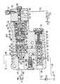
- the drawing shows a longitudinal section through a hydraulic control device with hydraulic system in a schematic representation.
- the control device has a valve housing 10 with a continuous longitudinal bore 11, to which a delivery line 12 is connected, into which a pump 13 delivers pressure medium from a container 14.
- a control slide 15 of a flow control valve 16 is slidably guided, on which a control spring 17 acts against the inflowing pressure medium.
- the rear part of the bore 18, in which the regulator spring is arranged, is sealed off by a screw plug 19. Facing the inlet 20 of the longitudinal bore 11, two triangular notches 21 are formed on the end face of the control slide 15.
- an orifice 24 Arranged in the interior of the control slide 15 is an orifice 24, downstream of which an orifice 25 with a much smaller diameter than that of the orifice 24.
- Three annular grooves 26, 27, 28 are formed on the longitudinal bore 11.
- a bore 29 extends from the annular groove 26 to the outside of the valve housing; there a return line 30 is connected, which leads to the container 14 or to other consumers.
- a throttle disk 32 is arranged, via which the regulator spring 17 acts on the control slide 15. The throttle disk 32 merely dampens the movement of the control slide 15.
- a channel 35 opens into the annular groove 27, into which a housing bore 36 penetrates, in which a valve insert 37 with a conical check valve 38 is inserted.
- a channel 39 extends from the housing bore 36 and opens into a longitudinal bore 40 running parallel to the longitudinal bore 11.
- a channel 43 which opens into an annular groove 47 at an enlarged part 40 'of the longitudinal bore 40.
- a plurality of radial bores 44 which are at the height of the Ring groove 27 lie.
- a plurality of radial bores 46 which lie at the level of the annular groove 28, open into the hollow control slide downstream of the throttle bore 25.
- a cup-shaped housing insert 49 is arranged, in the housing bore 50 a slide 51 is slidably mounted.
- a piston 52 is attached, the left part 52 'slides tightly in a bore 50 running axially to the housing bore 50, while its right part 52' is guided outwards by a sealing collar 54, which is supported on a disk 55.
- the right end face 52 ⁇ of the piston 52 is supported on the end face 155 'of a stepped piston 155, which is slidably arranged in a suitable stepped bore 56 of a piston-shaped spring abutment 58 and is loaded by a compression spring 57, which presses it against the end face 52 ⁇ of the piston 52 presses.
- the spring abutment 58 is arranged in a piston 59, which is slidably mounted in a bore 60, which is coaxial with the housing bore 40.
- Springs 61, 62 act on the spring abutment.
- the bore 60 is closed by a housing 64 in which a longitudinal bore 65 is formed, which runs coaxially with the housing bore 40.
- a piston 66 is mounted in a tightly sliding manner. It has a plunger 67 which lies against a locking screw 68 which closes the longitudinal bore 65.
- In the longitudinal bore 65 opens a transverse bore 69 extending in the housing 64, to which a line 70 is connected. This is based on a pressure sensor 71 which can be actuated by a brake pedal 72.
- a ventilation device 73 is also connected to the longitudinal bore 65.
- the annular wall 51 'of the slide is broken through a transverse bore 76, the end wall through a bore 75; the former opens into an annular groove 77 which interacts with an annular groove 78 in the housing insert 49.
- the two ring grooves 77, 78 are the wall of the Housing insert 49 penetrating transverse bore 79 in connection with one another and thus with the channel 43.
- an oblique bore 81 extends into an annular groove 82 of the bore part 40 'of the housing bore 40.
- a bore 83 extends from the annular groove 82 to the outside of the housing .
- a longitudinal bore 85 from which a transverse bore 86 extends outwards and in a certain position of the slide 51 has connection to the space 80.
- a line 88 leads from the longitudinal bore 40 to a brake cylinder 89.
- a line 96 runs from the bore 83 to the container 14.
- the control device works as follows:
- the pump 13 conveys pressure medium via the inlet into the longitudinal bore 11, which also reaches the inside of the control slide. A part of this pressure medium flows via the orifice 24, the throttle bore 25 and the throttle disk 32 into the space 18. A flow of control oil flows through the throttle bore 25 to the transverse bore 46, from there into the annular groove 47 and into the transverse bore 79 of the housing insert 49 and then into the annular grooves 78, 77 and the transverse bore 76 in the space 80. From there, the pressure medium flows through the oblique bore 81 and the line 96 to the container 14.
- control slide 15 is displaced to the right against the force of the regulator spring 17 and, via the triangular notches 21, connects to the annular groove 26 and to the line 30 and thus to the container or other consumers.
- part of the pressure medium conveyed by the pump 13 is passed into the channel 35 and via the check valve 38 which opens into the channel 39, further into the longitudinal bore 40 and into the line 88 and to the brake cylinder 89.
- the piston 52 is shifted to the right, taking the slide 51 with it.
- the annular groove 77 reconnects via the line 96 to the container 14, as a result of which the pressure in the channel 43 drops.
- control slide 15 of the flow control valve is displaced to the right against the force of the control spring 17, as a result of which the pressure medium delivered by the pump 13 flows out via the triangular notches 21, the annular groove 26 connected to the latter and the line 30 to the container or other consumers.
- the spring 57 ensures a decoupling between the control circuit, ie the brake pedal 72, the pressure transmitter (piston 66) on the one hand and the pilot control of the brake valve on the other hand, which consists in particular of the slide 51 and the piston 52.
- the piston 52 When the preselected brake pressure is reached, the piston 52 is pushed to the right.
- the piston 52 has to adjust the pressure springs 61, 62, the piston 66 and even the driver's foot (the pressure springs 61, 62 have the task of limiting the brake pressure). Since all parts have friction, have to be accelerated and the driver's foot also acts as a spring, the pressure in the brake circuit rises very high during this process. The only results are Few pressure levels when building up pressure and no sensitive braking.
- the number of pressure stages depends on the spring rate of the spring 57 and the spring travel. In this way you get a larger number of pressure levels and therefore a smoother braking.
- the compression spring 57 one or more disc springs can also be used with a correspondingly modified construction.
Landscapes
- Engineering & Computer Science (AREA)
- Transportation (AREA)
- Mechanical Engineering (AREA)
- Safety Valves (AREA)
- Valves And Accessory Devices For Braking Systems (AREA)
- Braking Systems And Boosters (AREA)
Abstract
Description
- Die Erfindung geht aus von einer hydraulischen Steuereinrichtung nach der Gattung des Hauptanspruchs. Bei einer derartigen bekannten Einrichtung erfolgt der Druckaufbau in relativ wenigen Druckstufen, was unter Umständen einen ruckhaften Bremsbetrieb ergibt.
- Die erfindungsgemäße Steuereinrichtung mit den kennzeichnenden Merkmalen des Hauptanspruchs hat demgegenüber den Vorteil, daß der Druckaufbau in mehreren Stufen erfolgt als bisher, was zu einem ruckfreien Bremsbetrieb führt.
- Ein Ausführungsbeispiel der Erfindung ist in der Zeichnung dargestellt und in der nachfolgenden Beschreibung näher erläutert. Die Zeichnung zeigt einen Längsschnitt durch eine hydraulische Steuereinrichtung mit Hydraulikanlage in schematischer Darstellung.
- Die Steuereinrichtung weist ein Ventilgehäuse 10 mit einer durchgehenden Längsbohrung 11 auf, an welche eine Förderleitung 12 angeschlossen ist, in die eine Pumpe 13 aus einem Behälter 14 Druckmittel fördert. In der Längsbohrung 11 ist ein Steuerschieber 15 eines Stromregelventils 16 gleitend geführt, auf den entgegen dem einströmenden Druckmittel eine Reglerfeder 17 einwirkt. Der hintere Teil der Bohrung 18, in welchem die Reglerfeder angeordnet ist, ist durch eine Verschlußschraube 19 dicht abgeschlosen. Dem Einlaß 20 der Längsbohrung 11 zugewandt, sind an der Stirnseite des Steuerschiebers 15 zwei Dreieckkerben 21 ausgebildet.
- Im Inneren des Steuerschiebers 15 ist eine Blende 24 angeordnet, stromabwärts von dieser eine Drossel 25 mit wesentlich kleinerem Durchmesser als dem der Blende 24. An der Längsborung 11 sind drei Ringnuten 26, 27, 28 ausgebildet. Von der Ringnut 26 verläuft eine Bohrung 29 zum Äußeren des Ventilgehäuses; dort ist eine Rückleitung 30 angeschlossen, die zum Behälter 14 oder zu weiteren Verbrauchern führt. Im hintersten Teil des Steuerschiebers 15 ist eine Drosselscheibe 32 angeordnet, über welche die Reglerfeder 17 auf den Steuerschieber 15 einwirkt. Die Drosselscheibe 32 bewirkt lediglich eine Dämpfung der Bewegung des Steuerschiebers 15. In die Ringnut 27 mündet ein Kanal 35, in den eine Gehäusebohrung 36 eindringt, in welcher ein Ventileinsatz 37 mit kegeligem Rückschlagventil 38 eingesetzt ist. Von der Gehäusebohrung 36 geht ein Kanal 39 aus, der in eine parallel zur Längsbohrung 11 verlaufende Längsbohrung 40 mündet.
- Von der Ringnut 28 geht ein Kanal 43 aus, welcher in eine Ringnut 47 an einem erweiterten Teil 40′ der Längsbohrung 40 mündet. In den zwischen der Blende 24 und der Drosselbohrung 25 gelegenen Raum 45 im Steuerschieber münden mehrere Radialbohrungen 44, die in Höhe der Ringnut 27 liegen. Stromabwärts der Drosselbohrung 25 münden in den hohlen Steuerschieber mehrere Radialbohrungen 46, die in Höhe der Ringnut 28 liegen.
- Im erweiterten Teil 40′ der Längsbohrung 40 ist ein becherförmiger Gehäuseeinsatz 49 angeordnet, in dessen Gehäusebohrung 50 ein Schieber 51 gleitend gelagert ist. An diesem ist ein Kolben 52 befestigt, dessen linker Teil 52′ dicht in einem achsgleich zur Gehäusebohrung 50 verlaufenden Bohrungsteil 53 gleitet, während sein rechter Teil 52˝ durch eine Dichtmanschette 54 nach außen geführt ist, die sich an einer Scheibe 55 abstützt. Die rechte Stirnseite 52˝ des Kolbens 52 stützt sich an der Stirnseite 155′ eines Stufenkolbens 155 ab, der in einer passenden Stufenbohrung 56 eines kolbenförmigen Federwiderlagers 58 gleitend angeordnet und von einer Druckfeder 57 belastet ist, die ihn an die Stirnseite 52˝ des Kolbens 52 drückt. Das Federwiderlager 58 ist in einem Kolben 59 angeordnet, der in einer Bohrung 60 gleitend gelagert ist, die achsgleich zur Gehäusebohrung 40 verläuft. Auf das Federwiderlager wirken Federn 61, 62 ein. Die Bohrung 60 ist durch ein Gehäuse 64 verschlossen, in dem eine Längsbohrung 65 ausgebildet ist, die achsgleich zur Gehäusebohrung 40 verläuft. In der Längsbohrung 65 ist ein Kolben 66 dicht gleitend gelagert. Er hat einen Stößel 67, der sich gegen eine die Längsbohrung 65 verschließende Verschlußschraube 68 legt. In die Längsbohrung 65 mündet eine im Gehäuse 64 verlaufende Querbohrung 69, an welche eine Leitung 70 angeschlossen ist. Diese geht aus von einem Druckgeber 71, der durch ein Bremspedal 72 betätigbar ist. An die Längsbohrung 65 ist noch eine Entlüftungsvorrichtung 73 angeschlossen.
- Die Ringwand 51′ des Schiebers ist durch eine Querbohrung 76 durchbrochen, die Stirnwand durch eine Bohrung 75; erstere mündet in eine Ringnut 77, die mit einer Ringnut 78 im Gehäuseeinsatz 49 zusammenwirkt. Die beiden Ringnuten 77, 78 stehen über eine die Wand des Gehäuseeinsatzes 49 durchdringende Querbohrung 79 miteinander in Verbindung und damit mit dem Kanal 43. Vom Raum 80 innerhalb des Gehäuseeinsatzes 49 verläuft eine Schrägbohrung 81 in eine Ringnut 82 des Bohrungsteils 40′ der Gehäusebohrung 40. Von der Ringnut 82 verläuft eine Bohrung 83 zum Äußeren des Gehäuses. Im linken Teil 52′ des Kolbens 52 befindet sich eine Längsbohrung 85, von der eine Querbohrung 86 nach außen verläuft und in einer bestimmten Stellung des Schiebers 51 Verbindung zum Raum 80 hat. Von ,der Längsbohrung 40 führt eine Leitung 88 zu einem Bremszylinder 89. Von der Bohrung 83 verläuft eine Leitung 96 zum Behälter 14.
- Die Steuereinrichtung arbeitet wie folgt:
- Die Pumpe 13 fördert Druckmittel über den Einlaß in die Längsbohrung 11, wobei dieses auch in das Innere des Steuerschiebers gelangt. Ein Teil dieses Druckmittels fließt über die Blende 24, die Drosselbohrung 25 und die Drosselscheibe 32 in den Raum 18. Über die Drosselbohrung 25 fließt ein Steuerölstrom zur Querbohrung 46, von dieser in die Ringnut 47 und in die Querbohrung 79 des Gehäuseeinsatzes 49 und dann in die Ringnuten 78, 77 und die Querbohrung 76 in den Raum 80. Von dort fließt das Druckmittel über die Schrägbohrung 81 und die Leitung 96 zum Behälter 14 ab.
- Infolge des Durchflußwiderstands an der Blende 25 und der dabei erzeugten Druckdifferenz wird der Steuerschieber 15 entgegen der Kraft der Reglerfeder 17 nach rechts verschoben und stellt über die Dreieckkerben 21 Verbindung zur Ringnut 26 und zur Leitung 30 und damit zum Behälter bzw. anderen Verbrauchern her.
- Wenn das Bremspedal 72 betätigt wird, baut sich in der Leitung 70 und in den Bohrungen 69 und 65 Druck auf, und der Kolben 66 wird entgegen dem Kolben 59 nach links verschoben. Das Federwiderlager 58 drückt über den Kolben 155 auf den Kolben 52, wodurch dieser nach links verschoben wird samt dem Schieber 51. Dadurch wird die Querbohrung 86 verschlossen, so daß die Verbindung von der Bohrung 40 zum Raum 80 unterbrochen ist. Danach unterbricht der Schieber 51 auch die Verbindung vom Kanal 43 zum Raum 80, so daß kein Steueröl mehr zum Behälter 14 abfließen kann. Dadurch wird die Druckdifferenz an der Blende 25 abgebaut,und die Feder 17 bewegt den Steuerschieber 15 nach links, wodurch die Querbohrungen 44 mit der Ringnut 27 in Verbindung kommen. Nun wird aufgrund des Druckabfalls an der Blende 24 ein Teil des von der Pumpe 13 geförderten Druckmittels in den Kanal 35 und über das sich öffnende Rückschlagventil 38 in den Kanal 39 geleitet, weiterhin von dort in die Längsbohrung 40 sowie in die Leitung 88 und zum Bremszylinder 89. Ist der durch die Pedalkraft eingegebene Druck erreicht, wird der Kolben 52 nach rechts verschoben, wobei er den Schieber 51 mitnimmt. Die Ringnut 77 stellt wieder Verbindung über die Leitung 96 zum Behälter 14 her, wodurch der Druck im Kanal 43 fällt. Dadurch wird der Steuerschieber 15 des Stromregelventils entgegen der Kraft der Reglerfeder 17 nach rechts verschoben, wodurch das von der Pumpe 13 geförderte Druckmittel über die Dreieckkerben 21, die mit diesen verbundene Ringnut 26 und die Leitung 30 zum Behälter bzw. weiteren Verbrauchern abströmt.
- Die Feder 57 sorgt für eine Entkopplung zwischen dem Ansteuerkreis, d. h. dem Bremspedal 72, dem Druckgeber (Kolben 66) einerseits und der Vorsteuerung des Bremsventils andererseits, welche insbesondere aus dem Schieber 51 und dem Kolben 52 besteht. Wenn der vorgewählte Bremsdruck erreicht ist, wird der Kolben 52 nach rechts geschoben. Der Kolben 52 muß bei bekannten Steuereinrichtung die Druckfedern 61, 62, den Kolben 66 und sogar den Fuß des Fahrers verstellen (die Druckfedern 61, 62 haben die Aufgabe, den Bremsdruck zu begrenzen). Da alle Teile Reibung haben, beschleunigt werden müssen und der Fuß des Fahrers gewissermaßen auch eine Feder darstellt, steigt der Druck im Bremskreis bei diesem Vorgang sehr hoch. Die Folge sind nur wenige Druckstufen beim Druckaufbau und kein feinfühliges Bremsen. Durch die Entkopplung von Federwiderlager 58 und Kolben 55, wie oben beschrieben, ist die Anzahl der Druckstufen abhängig von der Federrate der Feder 57 und dem Federweg. Auf diese Weise erhält man eine größere Anzahl von Druckstufen und dadurch ein ruckfreieres Bremsen. Anstelle der Druckfeder 57 kann bei entsprechend abgewandelter Konstruktion auch eine oder mehrere Tellerfedern verwendet werden.
Claims (1)
Applications Claiming Priority (2)
| Application Number | Priority Date | Filing Date | Title |
|---|---|---|---|
| DE3826620A DE3826620A1 (de) | 1988-08-05 | 1988-08-05 | Hydraulische steuereinrichtung |
| DE3826620 | 1988-08-05 |
Publications (2)
| Publication Number | Publication Date |
|---|---|
| EP0356669A1 true EP0356669A1 (de) | 1990-03-07 |
| EP0356669B1 EP0356669B1 (de) | 1992-03-18 |
Family
ID=6360293
Family Applications (1)
| Application Number | Title | Priority Date | Filing Date |
|---|---|---|---|
| EP89112722A Expired - Lifetime EP0356669B1 (de) | 1988-08-05 | 1989-07-12 | Hydraulische Steuereinrichtung |
Country Status (2)
| Country | Link |
|---|---|
| EP (1) | EP0356669B1 (de) |
| DE (2) | DE3826620A1 (de) |
Cited By (1)
| Publication number | Priority date | Publication date | Assignee | Title |
|---|---|---|---|---|
| EP0761520A1 (de) * | 1995-09-12 | 1997-03-12 | Fahrzeugtechnik Ebern GmbH | Ventilanordung für einen Fremdkraft-Bremskreis einer hydraulischen Bremsanlage |
Citations (2)
| Publication number | Priority date | Publication date | Assignee | Title |
|---|---|---|---|---|
| FR2113963A1 (de) * | 1970-11-13 | 1972-06-30 | Bosch | |
| EP0136622A2 (de) * | 1983-10-05 | 1985-04-10 | Robert Bosch Gmbh | Hydraulische Steuereinrichtung |
-
1988
- 1988-08-05 DE DE3826620A patent/DE3826620A1/de not_active Withdrawn
-
1989
- 1989-07-12 DE DE8989112722T patent/DE58900986D1/de not_active Expired - Lifetime
- 1989-07-12 EP EP89112722A patent/EP0356669B1/de not_active Expired - Lifetime
Patent Citations (2)
| Publication number | Priority date | Publication date | Assignee | Title |
|---|---|---|---|---|
| FR2113963A1 (de) * | 1970-11-13 | 1972-06-30 | Bosch | |
| EP0136622A2 (de) * | 1983-10-05 | 1985-04-10 | Robert Bosch Gmbh | Hydraulische Steuereinrichtung |
Cited By (2)
| Publication number | Priority date | Publication date | Assignee | Title |
|---|---|---|---|---|
| EP0761520A1 (de) * | 1995-09-12 | 1997-03-12 | Fahrzeugtechnik Ebern GmbH | Ventilanordung für einen Fremdkraft-Bremskreis einer hydraulischen Bremsanlage |
| US5816668A (en) * | 1995-09-12 | 1998-10-06 | Fahrzeugtechnik Ebern Gmbh | Valve apparatus for a non-muscular-energy-assisted brake circuit in a hydraulic brake system |
Also Published As
| Publication number | Publication date |
|---|---|
| EP0356669B1 (de) | 1992-03-18 |
| DE58900986D1 (de) | 1992-04-23 |
| DE3826620A1 (de) | 1990-02-08 |
Similar Documents
| Publication | Publication Date | Title |
|---|---|---|
| DE2644659A1 (de) | Vorrichtung fuer hydraulische bremssysteme mit blockiereinrichtung | |
| DE3037485C2 (de) | ||
| DE1555583C3 (de) | Drucksteuerventil für die hydraulische Bremsanlage eines Kraftfahrzeuges | |
| EP0267454A2 (de) | Hydraulisches Fahrzeugbremssystem | |
| EP0356669B1 (de) | Hydraulische Steuereinrichtung | |
| DE2335529B2 (de) | Hydraulischer Bremskraftverstärker | |
| EP0072951B1 (de) | Hydraulische Steuereinrichtung | |
| DE3401464C2 (de) | Hydraulische Steuereinrichtung | |
| EP0413930B1 (de) | Hydraulische Steuervorrichtung für die Bremse eines Anhängerfahrzeugs | |
| EP0122384B1 (de) | Hydraulische Steuereinrichtung | |
| DE3418172C2 (de) | Hydraulische Steuereinrichtung | |
| DE3712018C2 (de) | Hydraulische Steuereinrichtung | |
| EP0258587B1 (de) | Hydraulische Steuereinrichtung | |
| DE3242707A1 (de) | Hydraulische steuereinrichtung | |
| DE3938557C2 (de) | Hydraulische Steuereinrichtung | |
| DE3818250A1 (de) | Hydraulische steuereinrichtung | |
| DE3110466C2 (de) | Hydraulische Bremsvorrichtung mit Servowirkung | |
| DE60302566T2 (de) | Fluidproduktabgabepumpe | |
| DE3506137C2 (de) | Hydraulische Steuereinrichtung | |
| DE3442664A1 (de) | Hydraulische steuereinrichtung | |
| DE3301372A1 (de) | Hydraulische steuereinrichtung | |
| DE8806206U1 (de) | Hydraulische Steuereinrichtung | |
| DE2849397A1 (de) | Blockierschutz-fahrzeugbremsanlage | |
| DE3247471A1 (de) | Hydraulische steuereinrichtung | |
| DE3435396A1 (de) | Hydraulische steuereinrichtung |
Legal Events
| Date | Code | Title | Description |
|---|---|---|---|
| PUAI | Public reference made under article 153(3) epc to a published international application that has entered the european phase |
Free format text: ORIGINAL CODE: 0009012 |
|
| AK | Designated contracting states |
Kind code of ref document: A1 Designated state(s): DE FR GB IT |
|
| 17P | Request for examination filed |
Effective date: 19900726 |
|
| 17Q | First examination report despatched |
Effective date: 19910801 |
|
| GRAA | (expected) grant |
Free format text: ORIGINAL CODE: 0009210 |
|
| RAP3 | Party data changed (applicant data changed or rights of an application transferred) |
Owner name: ROBERT BOSCH GMBH |
|
| AK | Designated contracting states |
Kind code of ref document: B1 Designated state(s): DE FR GB IT |
|
| REF | Corresponds to: |
Ref document number: 58900986 Country of ref document: DE Date of ref document: 19920423 |
|
| ET | Fr: translation filed | ||
| GBT | Gb: translation of ep patent filed (gb section 77(6)(a)/1977) | ||
| ITF | It: translation for a ep patent filed | ||
| PLBE | No opposition filed within time limit |
Free format text: ORIGINAL CODE: 0009261 |
|
| STAA | Information on the status of an ep patent application or granted ep patent |
Free format text: STATUS: NO OPPOSITION FILED WITHIN TIME LIMIT |
|
| 26N | No opposition filed | ||
| PGFP | Annual fee paid to national office [announced via postgrant information from national office to epo] |
Ref country code: GB Payment date: 19930629 Year of fee payment: 5 |
|
| PG25 | Lapsed in a contracting state [announced via postgrant information from national office to epo] |
Ref country code: GB Effective date: 19940712 |
|
| GBPC | Gb: european patent ceased through non-payment of renewal fee |
Effective date: 19940712 |
|
| PGFP | Annual fee paid to national office [announced via postgrant information from national office to epo] |
Ref country code: DE Payment date: 20010420 Year of fee payment: 12 |
|
| PG25 | Lapsed in a contracting state [announced via postgrant information from national office to epo] |
Ref country code: DE Free format text: LAPSE BECAUSE OF NON-PAYMENT OF DUE FEES Effective date: 20020501 |
|
| PGFP | Annual fee paid to national office [announced via postgrant information from national office to epo] |
Ref country code: FR Payment date: 20030716 Year of fee payment: 15 |
|
| PG25 | Lapsed in a contracting state [announced via postgrant information from national office to epo] |
Ref country code: FR Free format text: LAPSE BECAUSE OF NON-PAYMENT OF DUE FEES Effective date: 20050331 |
|
| REG | Reference to a national code |
Ref country code: FR Ref legal event code: ST |
|
| PG25 | Lapsed in a contracting state [announced via postgrant information from national office to epo] |
Ref country code: IT Free format text: LAPSE BECAUSE OF NON-PAYMENT OF DUE FEES;WARNING: LAPSES OF ITALIAN PATENTS WITH EFFECTIVE DATE BEFORE 2007 MAY HAVE OCCURRED AT ANY TIME BEFORE 2007. THE CORRECT EFFECTIVE DATE MAY BE DIFFERENT FROM THE ONE RECORDED. Effective date: 20050712 |