EP0356830A2 - Machine-outil - Google Patents
Machine-outil Download PDFInfo
- Publication number
- EP0356830A2 EP0356830A2 EP89115227A EP89115227A EP0356830A2 EP 0356830 A2 EP0356830 A2 EP 0356830A2 EP 89115227 A EP89115227 A EP 89115227A EP 89115227 A EP89115227 A EP 89115227A EP 0356830 A2 EP0356830 A2 EP 0356830A2
- Authority
- EP
- European Patent Office
- Prior art keywords
- spindle
- tool
- cavity
- tool holder
- machine tool
- Prior art date
- Legal status (The legal status is an assumption and is not a legal conclusion. Google has not performed a legal analysis and makes no representation as to the accuracy of the status listed.)
- Granted
Links
Images

Classifications
-
- B—PERFORMING OPERATIONS; TRANSPORTING
- B23—MACHINE TOOLS; METAL-WORKING NOT OTHERWISE PROVIDED FOR
- B23Q—DETAILS, COMPONENTS, OR ACCESSORIES FOR MACHINE TOOLS, e.g. ARRANGEMENTS FOR COPYING OR CONTROLLING; MACHINE TOOLS IN GENERAL CHARACTERISED BY THE CONSTRUCTION OF PARTICULAR DETAILS OR COMPONENTS; COMBINATIONS OR ASSOCIATIONS OF METAL-WORKING MACHINES, NOT DIRECTED TO A PARTICULAR RESULT
- B23Q13/00—Equipment for use with tools or cutters when not in operation, e.g. protectors for storage
-
- B—PERFORMING OPERATIONS; TRANSPORTING
- B23—MACHINE TOOLS; METAL-WORKING NOT OTHERWISE PROVIDED FOR
- B23Q—DETAILS, COMPONENTS, OR ACCESSORIES FOR MACHINE TOOLS, e.g. ARRANGEMENTS FOR COPYING OR CONTROLLING; MACHINE TOOLS IN GENERAL CHARACTERISED BY THE CONSTRUCTION OF PARTICULAR DETAILS OR COMPONENTS; COMBINATIONS OR ASSOCIATIONS OF METAL-WORKING MACHINES, NOT DIRECTED TO A PARTICULAR RESULT
- B23Q3/00—Devices holding, supporting, or positioning work or tools, of a kind normally removable from the machine
- B23Q3/155—Arrangements for automatic insertion or removal of tools, e.g. combined with manual handling
- B23Q3/157—Arrangements for automatic insertion or removal of tools, e.g. combined with manual handling of rotary tools
- B23Q3/15706—Arrangements for automatic insertion or removal of tools, e.g. combined with manual handling of rotary tools a single tool being inserted in a spindle directly from a storage device, i.e. without using transfer devices
-
- B—PERFORMING OPERATIONS; TRANSPORTING
- B23—MACHINE TOOLS; METAL-WORKING NOT OTHERWISE PROVIDED FOR
- B23Q—DETAILS, COMPONENTS, OR ACCESSORIES FOR MACHINE TOOLS, e.g. ARRANGEMENTS FOR COPYING OR CONTROLLING; MACHINE TOOLS IN GENERAL CHARACTERISED BY THE CONSTRUCTION OF PARTICULAR DETAILS OR COMPONENTS; COMBINATIONS OR ASSOCIATIONS OF METAL-WORKING MACHINES, NOT DIRECTED TO A PARTICULAR RESULT
- B23Q3/00—Devices holding, supporting, or positioning work or tools, of a kind normally removable from the machine
- B23Q3/155—Arrangements for automatic insertion or removal of tools, e.g. combined with manual handling
- B23Q3/157—Arrangements for automatic insertion or removal of tools, e.g. combined with manual handling of rotary tools
- B23Q3/15713—Arrangements for automatic insertion or removal of tools, e.g. combined with manual handling of rotary tools a transfer device taking a single tool from a storage device and inserting it in a spindle
-
- Y—GENERAL TAGGING OF NEW TECHNOLOGICAL DEVELOPMENTS; GENERAL TAGGING OF CROSS-SECTIONAL TECHNOLOGIES SPANNING OVER SEVERAL SECTIONS OF THE IPC; TECHNICAL SUBJECTS COVERED BY FORMER USPC CROSS-REFERENCE ART COLLECTIONS [XRACs] AND DIGESTS
- Y10—TECHNICAL SUBJECTS COVERED BY FORMER USPC
- Y10T—TECHNICAL SUBJECTS COVERED BY FORMER US CLASSIFICATION
- Y10T409/00—Gear cutting, milling, or planing
- Y10T409/30—Milling
- Y10T409/30392—Milling with means to protect operative or machine [e.g., guard, safety device, etc.]
-
- Y—GENERAL TAGGING OF NEW TECHNOLOGICAL DEVELOPMENTS; GENERAL TAGGING OF CROSS-SECTIONAL TECHNOLOGIES SPANNING OVER SEVERAL SECTIONS OF THE IPC; TECHNICAL SUBJECTS COVERED BY FORMER USPC CROSS-REFERENCE ART COLLECTIONS [XRACs] AND DIGESTS
- Y10—TECHNICAL SUBJECTS COVERED BY FORMER USPC
- Y10T—TECHNICAL SUBJECTS COVERED BY FORMER US CLASSIFICATION
- Y10T483/00—Tool changing
- Y10T483/11—Tool changing with safety means
- Y10T483/115—Guard
-
- Y—GENERAL TAGGING OF NEW TECHNOLOGICAL DEVELOPMENTS; GENERAL TAGGING OF CROSS-SECTIONAL TECHNOLOGIES SPANNING OVER SEVERAL SECTIONS OF THE IPC; TECHNICAL SUBJECTS COVERED BY FORMER USPC CROSS-REFERENCE ART COLLECTIONS [XRACs] AND DIGESTS
- Y10—TECHNICAL SUBJECTS COVERED BY FORMER USPC
- Y10T—TECHNICAL SUBJECTS COVERED BY FORMER US CLASSIFICATION
- Y10T483/00—Tool changing
- Y10T483/17—Tool changing including machine tool or component
- Y10T483/1733—Rotary spindle machine tool [e.g., milling machine, boring, machine, grinding machine, etc.]
- Y10T483/1748—Tool changer between spindle and matrix
- Y10T483/1752—Tool changer between spindle and matrix including tool holder pivotable about axis
Definitions
- the invention relates to a machine tool with a rotating spindle and with a plurality of tool holders which have a cone and can be inserted individually with the cone into a working position in the spindle by means of a gripping arm from a magazine position spaced from the spindle, while the other tool holders in the magazine position remain.
- a machine tool of the type mentioned above is known from DE-PS 32 33 934.
- the headstock is aligned with the spindle with a vertical axis and can be moved along several coordinate axes relative to a workpiece table.
- a sleeve surrounding the spindle is provided on the headstock and can be displaced in the vertical direction relative to the spindle.
- the sleeve carries a plurality of gripping arms which can be pivoted essentially in a plane extending radially to the spindle axis.
- the gripper arms each have parallelogram guides and run out at their lower end into a gripper, which is each equipped with a tool holder.
- the gripping arms with the tool holders are pivoted vertically upward, so that the tool holders with the tools are arranged both above and laterally at a distance from the spindle.
- one of the gripping arms is now pivoted downward, the insertion movement of the tool holder into the spindle receiving being achieved by relative movement of the sleeve on the headstock, regardless of the absolute vertical position of the spindle relative to the workpiece table.
- the tool holders are provided with standardized cones which fit into a correspondingly shaped conical receptacle of the spindle.
- the invention is therefore based on the object of developing a machine tool of the type mentioned at the outset such that faults of the type mentioned above are avoided.
- the tool holders are held on their way between the magazine position and the working position essentially in a vertical axis and the cavity is designed as a quiver which is open at the bottom.
- This measure has the advantage in machine tools with a known constant vertical axis alignment of the tool holder that the cavity is only open at the bottom, so that the probability is very low that metal chips can get into the quiver thus formed when a tool in the Working position and the associated quiver is free.
- the gripping arms are arranged distributed around the spindle and are jointly fastened to a sleeve which is displaceable relative to the spindle in the direction of the spindle axis, the sleeve then being provided with the cavity.
- This measure has the advantage that only relatively small cavities need to be provided, e.g. can be formed as individual quivers, caps and the like. An interaction between the individual cavities is also excluded, so that even if a metal chip should get into one of the cavities, the remaining cavities are not affected, e.g. when one of the cavities becomes accessible because the tool in question is in the working position.
- a cover is provided to close the cavity when the associated tool holder is in the working position.
- This measure has the significant advantage that metal chips cannot even get indirectly onto the cone of the tool holder, for example by penetrating into an open cavity of a tool holder currently in the working position and then later settling on the cone, which after completion of the respective processing step is returned to the cavity in question.
- cover is designed as a sheet on a pivotable section of the gripping arm, the sheet being pivoted from the magazine position when the tool holder is pivoted is automatically pivoted into the working position by means of the gripping arm into a position closing the cavity.
- This measure has the particular advantage that no separate actuating means have to be provided in order to close the cavity, because the sheet metal automatically sets itself in front of the opening of the cavity when the associated tool holder is transferred from the magazine position into the working position. It is also advantageous that the sheet can be formed in a variety of ways, e.g. to protect other units in the vicinity of the machine tool.
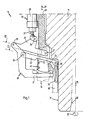
- FIG. 1 designates a machine tool according to the invention, in which a headstock has a rotating spindle 11 with a conical receptacle 12.
- the receptacle 12 of the spindle 11 is designed so that it is complementary to a cone 13 of a standard tool holder 14.
- the tool holders 14 are held in the machine tool 10 in a position in which their axis runs parallel to a spindle axis 15.
- the tool holder 14 are provided below the cone 13 with an annular flange 16 to which a tool, for example a drill or a milling cutter, is connected at the bottom.
- a plurality of tool holders 14 are arranged around the spindle 11 and can each be pivoted individually from the magazine position of the tool holder 14 shown in FIG. 1 into a working position in the receptacle 12 of the spindle 11, as will be explained below with reference to FIG. 2 and 3 will be explained.
- a tool changer is provided for replacing tool holders 14 in the spindle 11 or for subsequent replacement, which essentially consists of a gripper arm 20 operated by an external force.
- the gripper arm 20 goes down into a gripper 21 which grips the tool holder 14 in the region of the ring flange 16.
- the gripper 21 is preferably designed so that the tool holder 14 is rotatably held in it, so that the gripper 21 remains in the working position of the tool holder 14 in order to reduce the tool changing times in this way.
- the gripper 21 is part of a parallelogram guide, which also consists of a first rod 22 and a second rod 23 parallel to it.
- the bars 22, 23 are mounted on the gripper 21 by means of a first axis 24 or a second axis 25 under their respective opposite ends in a third axis 26 or a fourth axis 27.
- the axes 24 to 27 run perpendicular to the plane of the drawing in FIG. 1.
- the third axis 26 and the fourth axis 27 are located on a sleeve 28 which surrounds the spindle 11.
- the sleeve 28 can be displaced vertically relative to the spindle 11 in a manner known per se, as indicated by an arrow 29. Since the spindle 11 rotates with respect to the sleeve 28, a bearing 30 is provided between the sleeve 28 and the spindle 11 in the lower region of the sleeve 28 and runs on a cylindrical surface 31 of the spindle 11. The direction of rotation of the spindle 11 is indicated by an arrow 32.
- the first rod 22 is provided on its underside with a recess 33, the meaning of which with respect to the bearing 30 will be explained below.
- a piston-cylinder unit 35 is articulated on an upper projection of the second rod 23 via a fifth axis 36, which runs parallel to the axes 24 to 27.
- the piston-cylinder unit 35 essentially consists of a piston 37 which articulates on the fifth axis 36 and a cylinder 38 which at its upper end (not shown in FIG. 1) is pivotable on a radial projection of the sleeve 28 is stored.
- Fig. 1 shows the tool holder 14 in the magazine position in which the piston 37 is completely retracted into the cylinder 38.
- the sleeve 28 is also in its upper end position relative to the spindle 11.
- the rods 22, 23 are in the magazine position in an approximately horizontal orientation, the axes 24, 25 being somewhat higher than the axes 26, 27.
- the cone 13 of the tool holder 14 is inserted into a cavity 40 which adjoins the underside of a radial projection of the sleeve 28 is located.
- the cavity 40 is designed in the manner of a quiver and in each case surrounds the cone of one of the plurality of tool holders 14.
- the cavity 40 is also closed at the bottom when the tool holder 14 is inserted. This means that the cone 13 is completely covered in the magazine position. If now a tool of another Tool holder, which is just inserted into the spindle holder 12, works on a workpiece and a mixture of drilling water and metal chips flies around at high chip speeds, so no metal chips can settle on the cone 13 of the other tool holders 14, because they are all in the magazine position and kept covered in cavity 40.
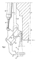
- FIG. 2 shows an intermediate position in which the piston 37 has been extended downward from the cylinder 38.
- the sleeve 28 was moved downwards in the direction of the arrow 29.
- the rods 22, 23 assume a position inclined downward to the left.
- the cone 13 of the tool holder 14 is now also below the lower edge of the spindle 11.
- the arrangement is such that when the piston 37 is extended further, the rods 22, 23 are pivoted further down until they reach a vertical end position in which the tool holder 14 is aligned with the spindle axis 15.
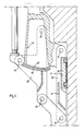
- FIG. 4 shows further details of the representation according to FIG. 3 and it can first be seen that the cavity 40 has a lower opening 45 which would be open in the working position of the associated tool holder because it is no longer closed by the ring flange 16.
- a first sheet 46 or a corresponding plastic part is provided on the second rod 23 and extends essentially perpendicular to the plane of the drawing in FIG. 4.
- the first sheet 46 is approximately in the form of a hollow cylinder segment, the longitudinal axis of which coincides with the fourth axis 27.
- a similar second sheet 47 is also provided on the first rod 22, with which the bearing 30 is covered downward.
- the sheets 46, 47 also serve as mechanical stiffening for side parts from which the rods 22, 23 are made.
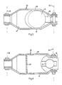
- first rod 22 shows for the first rod 22 that it consists of two folding parts 50, 51 arranged symmetrically, which are combined at their ends in axes 24, 26.
- the second plate 47 extends between these side parts 50, 51 and stiffens them, a corresponding circular arc-shaped recess being provided on the second plate 57.
- a first holder 52 can also be provided between the side parts 50, 51 in order to prevent the tool holder 14 from tilting.
- FIG. 6 shows side parts 60, 61 of the second rod 23 in a corresponding manner.
- the first plate 46 which now runs perpendicular to the plane of the drawing in FIG. 6, also serves as a recess between the plates 60, 61. Again, there is a holder 62 provided to prevent tilting of the tool holder 14.
Landscapes
- Engineering & Computer Science (AREA)
- Mechanical Engineering (AREA)
- Automatic Tool Replacement In Machine Tools (AREA)
- Auxiliary Devices For Machine Tools (AREA)
Applications Claiming Priority (2)
| Application Number | Priority Date | Filing Date | Title |
|---|---|---|---|
| DE3829105A DE3829105A1 (de) | 1988-08-27 | 1988-08-27 | Werkzeugmaschine |
| DE3829105 | 1988-08-27 |
Publications (3)
| Publication Number | Publication Date |
|---|---|
| EP0356830A2 true EP0356830A2 (fr) | 1990-03-07 |
| EP0356830A3 EP0356830A3 (en) | 1990-08-08 |
| EP0356830B1 EP0356830B1 (fr) | 1993-02-24 |
Family
ID=6361708
Family Applications (1)
| Application Number | Title | Priority Date | Filing Date |
|---|---|---|---|
| EP89115227A Expired - Lifetime EP0356830B1 (fr) | 1988-08-27 | 1989-08-18 | Machine-outil |
Country Status (5)
| Country | Link |
|---|---|
| US (1) | US4930208A (fr) |
| EP (1) | EP0356830B1 (fr) |
| JP (1) | JP2711908B2 (fr) |
| DE (2) | DE3829105A1 (fr) |
| ES (1) | ES2039777T3 (fr) |
Cited By (3)
| Publication number | Priority date | Publication date | Assignee | Title |
|---|---|---|---|---|
| EP0481276A1 (fr) * | 1990-10-09 | 1992-04-22 | Chiron-Werke GmbH & Co. KG | Machine-outil |
| US5947877A (en) * | 1997-12-19 | 1999-09-07 | Wei; Sun Ho | Tool shift device in a computer machine |
| CN106493597A (zh) * | 2015-09-07 | 2017-03-15 | 德马吉森精机株式会社 | 机床 |
Families Citing this family (9)
| Publication number | Priority date | Publication date | Assignee | Title |
|---|---|---|---|---|
| DE4329252A1 (de) * | 1993-08-31 | 1995-03-02 | Chiron Werke Gmbh | Werkzeugmaschine |
| JPH0731250U (ja) * | 1993-11-24 | 1995-06-13 | 浜井産業株式会社 | マシニングセンタ |
| JPH07237070A (ja) * | 1994-02-28 | 1995-09-12 | Sumisho Wadoo Kk | 工具交換装置 |
| DE19616431C2 (de) * | 1996-04-25 | 2001-05-03 | Chiron Werke Gmbh | Werkzeugmaschine mit in Magazinposition geneigt angeordneten Werkzeughaltern |
| US6416450B2 (en) * | 1999-07-28 | 2002-07-09 | Thermwood Corporation | Machine tool with improved tool changer means |
| US6949057B2 (en) * | 2003-09-02 | 2005-09-27 | The Boeing Company | Multi-function end effector |
| US8607392B1 (en) | 2005-10-05 | 2013-12-17 | Columbia Insurance Company | Textile steamer assembly and method |
| JP6342534B2 (ja) * | 2017-03-01 | 2018-06-13 | 株式会社吉野機械製作所 | 金型交換装置 |
| BE1027041B1 (nl) | 2019-02-08 | 2020-09-08 | Nutrition Sciences Nv | Samenstelling voor gebruik bij de behandeling van piscirickettsiose |
Family Cites Families (14)
| Publication number | Priority date | Publication date | Assignee | Title |
|---|---|---|---|---|
| JPS5315229B2 (fr) * | 1974-02-26 | 1978-05-23 | ||
| US4196506A (en) * | 1976-09-07 | 1980-04-08 | Giddings & Lewis, Inc. | Tool changer machining center |
| JPS55120943A (en) * | 1979-03-09 | 1980-09-17 | Brother Ind Ltd | Tool replacing device for machine tool |
| JPS5540375A (en) * | 1979-04-09 | 1980-03-21 | Kubota Ltd | Flexible pipe with socket portion |
| US4499650A (en) * | 1982-06-24 | 1985-02-19 | Kentner B. Wilson | Automatic tool changer |
| DE3233934C2 (de) * | 1982-09-13 | 1986-10-23 | Chiron-Werke Gmbh, 7200 Tuttlingen | Werkzeugmaschine mit Werkzeugmagazin |
| EP0106081B1 (fr) * | 1982-09-13 | 1988-05-04 | Chiron-Werke GmbH | Machine-outil avec magasin d'outils |
| FR2547230A1 (fr) * | 1983-06-09 | 1984-12-14 | Moulin Georges | Dispositif changeur automatique d'outils, notamment pour machines-outils |
| JPS60155338A (ja) * | 1984-01-20 | 1985-08-15 | Brother Ind Ltd | 工作機械 |
| DE3447706A1 (de) * | 1984-12-28 | 1986-07-03 | Maho Werkzeugmaschinenbau Babel & Co, 8962 Pfronten | Werkzeugmagazin |
| JPS6219337A (ja) * | 1985-07-18 | 1987-01-28 | Yamazaki Mazak Corp | 工具収納交換方法 |
| DE3542506A1 (de) * | 1985-12-02 | 1987-06-04 | Kloeckner Humboldt Deutz Ag | Bearbeitungseinrichtung fuer werkstuecke |
| DE3627515C1 (de) * | 1986-08-13 | 1987-12-03 | Maho Ag | Werkzeugmagazin fuer insbesondere Fraes- und Bohrmaschinen |
| DE8716734U1 (de) * | 1987-12-18 | 1988-02-04 | Klarer, Christoph, 8028 Taufkirchen | Schutzhaube für eine Werkzeug-Aufnahme |
-
1988
- 1988-08-27 DE DE3829105A patent/DE3829105A1/de active Granted
-
1989
- 1989-08-18 DE DE8989115227T patent/DE58903598D1/de not_active Expired - Fee Related
- 1989-08-18 ES ES198989115227T patent/ES2039777T3/es not_active Expired - Lifetime
- 1989-08-18 EP EP89115227A patent/EP0356830B1/fr not_active Expired - Lifetime
- 1989-08-22 JP JP1214269A patent/JP2711908B2/ja not_active Expired - Lifetime
- 1989-08-24 US US07/398,084 patent/US4930208A/en not_active Expired - Lifetime
Cited By (3)
| Publication number | Priority date | Publication date | Assignee | Title |
|---|---|---|---|---|
| EP0481276A1 (fr) * | 1990-10-09 | 1992-04-22 | Chiron-Werke GmbH & Co. KG | Machine-outil |
| US5947877A (en) * | 1997-12-19 | 1999-09-07 | Wei; Sun Ho | Tool shift device in a computer machine |
| CN106493597A (zh) * | 2015-09-07 | 2017-03-15 | 德马吉森精机株式会社 | 机床 |
Also Published As
| Publication number | Publication date |
|---|---|
| JPH0283135A (ja) | 1990-03-23 |
| DE3829105C2 (fr) | 1992-08-27 |
| DE3829105A1 (de) | 1990-03-08 |
| US4930208A (en) | 1990-06-05 |
| JP2711908B2 (ja) | 1998-02-10 |
| ES2039777T3 (es) | 1993-10-01 |
| EP0356830A3 (en) | 1990-08-08 |
| EP0356830B1 (fr) | 1993-02-24 |
| DE58903598D1 (de) | 1993-04-01 |
Similar Documents
| Publication | Publication Date | Title |
|---|---|---|
| DE3410913A1 (de) | Werkzeugmaschine zur mechanischen und laserstrahl-bearbeitung eines werkstuecks | |
| EP1016497A2 (fr) | Machine-outil | |
| DE3242439C2 (de) | Werkzeugwechseleinrichtung | |
| EP0356830A2 (fr) | Machine-outil | |
| DE102008026330A1 (de) | Plattenaufteilanlage | |
| DE3032405A1 (de) | Raeumvorrichtung fuer hohlwellen | |
| EP0901862A2 (fr) | Machine de brochage | |
| DE102004031066A1 (de) | Werkzeugmaschine mit mindestens einer Arbeitsspindel | |
| DE8126751U1 (de) | Doppelständer-Portalschleifmaschine | |
| DE4031997C2 (fr) | ||
| DE19724635A1 (de) | Werkzeugmaschine mit Werkzeugauswechselvorrichtung | |
| EP0142749B1 (fr) | Dispositif de changement d'outil pour machine-outil multibroche | |
| DE3618959A1 (de) | Werkzeugmaschine zum spanabhebenden bearbeiten von werkstuecken | |
| EP0097271A1 (fr) | Machine à fraiser des vilebrequins | |
| DE1477429B2 (de) | Werkzeugmaschine mit automatischem Werkzeugwechsel | |
| DE4315997C2 (de) | Bearbeitungsmaschine für plattenförmige Werkstücke | |
| EP0811460A1 (fr) | Machine outil | |
| DE2757140A1 (de) | Schutzvorrichtung sowie mit dieser ausgeruestete bohrmaschine | |
| EP0092673A2 (fr) | Porte-outil pour supporter les outils de tournage d'un système | |
| DE102010007890B4 (de) | Werkzeugmaschine zum Bearbeiten von schlanken Werkstücken | |
| EP0854008A1 (fr) | Porte-outil pour un outil | |
| DE8708770U1 (de) | Werkzeugaufnahme | |
| DE3336232A1 (de) | Automatische werkzeugwechsel-einrichtung fuer werkzeug-maschinen | |
| DE3814674A1 (de) | Bohreinrichtung | |
| DE2319093C3 (de) | Automatische Burstenherstellungsmaschine |
Legal Events
| Date | Code | Title | Description |
|---|---|---|---|
| PUAI | Public reference made under article 153(3) epc to a published international application that has entered the european phase |
Free format text: ORIGINAL CODE: 0009012 |
|
| AK | Designated contracting states |
Kind code of ref document: A2 Designated state(s): CH DE ES FR GB IT LI SE |
|
| PUAL | Search report despatched |
Free format text: ORIGINAL CODE: 0009013 |
|
| AK | Designated contracting states |
Kind code of ref document: A3 Designated state(s): CH DE ES FR GB IT LI SE |
|
| 17P | Request for examination filed |
Effective date: 19901220 |
|
| 17Q | First examination report despatched |
Effective date: 19910726 |
|
| RTI1 | Title (correction) | ||
| GRAA | (expected) grant |
Free format text: ORIGINAL CODE: 0009210 |
|
| AK | Designated contracting states |
Kind code of ref document: B1 Designated state(s): CH DE ES FR GB IT LI SE |
|
| PG25 | Lapsed in a contracting state [announced via postgrant information from national office to epo] |
Ref country code: SE Effective date: 19930224 |
|
| ITF | It: translation for a ep patent filed | ||
| REF | Corresponds to: |
Ref document number: 58903598 Country of ref document: DE Date of ref document: 19930401 |
|
| ET | Fr: translation filed | ||
| GBT | Gb: translation of ep patent filed (gb section 77(6)(a)/1977) |
Effective date: 19930526 |
|
| PG25 | Lapsed in a contracting state [announced via postgrant information from national office to epo] |
Ref country code: CH Effective date: 19930831 Ref country code: LI Effective date: 19930831 |
|
| REG | Reference to a national code |
Ref country code: ES Ref legal event code: FG2A Ref document number: 2039777 Country of ref document: ES Kind code of ref document: T3 |
|
| PLBE | No opposition filed within time limit |
Free format text: ORIGINAL CODE: 0009261 |
|
| STAA | Information on the status of an ep patent application or granted ep patent |
Free format text: STATUS: NO OPPOSITION FILED WITHIN TIME LIMIT |
|
| 26N | No opposition filed | ||
| REG | Reference to a national code |
Ref country code: CH Ref legal event code: PL |
|
| REG | Reference to a national code |
Ref country code: GB Ref legal event code: IF02 |
|
| PGFP | Annual fee paid to national office [announced via postgrant information from national office to epo] |
Ref country code: FR Payment date: 20020614 Year of fee payment: 14 |
|
| PGFP | Annual fee paid to national office [announced via postgrant information from national office to epo] |
Ref country code: GB Payment date: 20020730 Year of fee payment: 14 |
|
| PG25 | Lapsed in a contracting state [announced via postgrant information from national office to epo] |
Ref country code: GB Free format text: LAPSE BECAUSE OF NON-PAYMENT OF DUE FEES Effective date: 20030818 |
|
| GBPC | Gb: european patent ceased through non-payment of renewal fee |
Effective date: 20030818 |
|
| PG25 | Lapsed in a contracting state [announced via postgrant information from national office to epo] |
Ref country code: FR Free format text: LAPSE BECAUSE OF NON-PAYMENT OF DUE FEES Effective date: 20040430 |
|
| REG | Reference to a national code |
Ref country code: FR Ref legal event code: ST |
|
| PGFP | Annual fee paid to national office [announced via postgrant information from national office to epo] |
Ref country code: ES Payment date: 20070830 Year of fee payment: 19 |
|
| PGFP | Annual fee paid to national office [announced via postgrant information from national office to epo] |
Ref country code: DE Payment date: 20070920 Year of fee payment: 19 |
|
| PGFP | Annual fee paid to national office [announced via postgrant information from national office to epo] |
Ref country code: IT Payment date: 20070824 Year of fee payment: 19 |
|
| PG25 | Lapsed in a contracting state [announced via postgrant information from national office to epo] |
Ref country code: DE Free format text: LAPSE BECAUSE OF NON-PAYMENT OF DUE FEES Effective date: 20090303 Ref country code: IT Free format text: LAPSE BECAUSE OF NON-PAYMENT OF DUE FEES Effective date: 20080818 |
|
| REG | Reference to a national code |
Ref country code: ES Ref legal event code: FD2A Effective date: 20080819 |
|
| PG25 | Lapsed in a contracting state [announced via postgrant information from national office to epo] |
Ref country code: ES Free format text: LAPSE BECAUSE OF NON-PAYMENT OF DUE FEES Effective date: 20080819 |