EP0356895A2 - Schweissgerät zum Verbinden der Enden zweier Bänder aus thermoplastischem Material - Google Patents
Schweissgerät zum Verbinden der Enden zweier Bänder aus thermoplastischem Material Download PDFInfo
- Publication number
- EP0356895A2 EP0356895A2 EP89115524A EP89115524A EP0356895A2 EP 0356895 A2 EP0356895 A2 EP 0356895A2 EP 89115524 A EP89115524 A EP 89115524A EP 89115524 A EP89115524 A EP 89115524A EP 0356895 A2 EP0356895 A2 EP 0356895A2
- Authority
- EP
- European Patent Office
- Prior art keywords
- welding
- sword
- welding device
- vertical stand
- welding sword
- Prior art date
- Legal status (The legal status is an assumption and is not a legal conclusion. Google has not performed a legal analysis and makes no representation as to the accuracy of the status listed.)
- Withdrawn
Links
- 238000003466 welding Methods 0.000 title claims abstract description 57
- 229920001169 thermoplastic Polymers 0.000 title 1
- 239000004416 thermosoftening plastic Substances 0.000 title 1
- 238000010438 heat treatment Methods 0.000 claims abstract description 12
- 239000000463 material Substances 0.000 claims abstract description 3
- 239000012815 thermoplastic material Substances 0.000 claims abstract description 3
- 238000009413 insulation Methods 0.000 claims 1
- 238000000034 method Methods 0.000 description 2
- 239000004809 Teflon Substances 0.000 description 1
- 229920006362 Teflon® Polymers 0.000 description 1
- 239000000919 ceramic Substances 0.000 description 1
Images
Classifications
-
- B—PERFORMING OPERATIONS; TRANSPORTING
- B29—WORKING OF PLASTICS; WORKING OF SUBSTANCES IN A PLASTIC STATE IN GENERAL
- B29C—SHAPING OR JOINING OF PLASTICS; SHAPING OF MATERIAL IN A PLASTIC STATE, NOT OTHERWISE PROVIDED FOR; AFTER-TREATMENT OF THE SHAPED PRODUCTS, e.g. REPAIRING
- B29C66/00—General aspects of processes or apparatus for joining preformed parts
- B29C66/01—General aspects dealing with the joint area or with the area to be joined
- B29C66/05—Particular design of joint configurations
- B29C66/10—Particular design of joint configurations particular design of the joint cross-sections
- B29C66/11—Joint cross-sections comprising a single joint-segment, i.e. one of the parts to be joined comprising a single joint-segment in the joint cross-section
- B29C66/114—Single butt joints
- B29C66/1142—Single butt to butt joints
-
- B—PERFORMING OPERATIONS; TRANSPORTING
- B29—WORKING OF PLASTICS; WORKING OF SUBSTANCES IN A PLASTIC STATE IN GENERAL
- B29C—SHAPING OR JOINING OF PLASTICS; SHAPING OF MATERIAL IN A PLASTIC STATE, NOT OTHERWISE PROVIDED FOR; AFTER-TREATMENT OF THE SHAPED PRODUCTS, e.g. REPAIRING
- B29C65/00—Joining or sealing of preformed parts, e.g. welding of plastics materials; Apparatus therefor
- B29C65/02—Joining or sealing of preformed parts, e.g. welding of plastics materials; Apparatus therefor by heating, with or without pressure
- B29C65/18—Joining or sealing of preformed parts, e.g. welding of plastics materials; Apparatus therefor by heating, with or without pressure using heated tools
- B29C65/20—Joining or sealing of preformed parts, e.g. welding of plastics materials; Apparatus therefor by heating, with or without pressure using heated tools with direct contact, e.g. using "mirror"
-
- B—PERFORMING OPERATIONS; TRANSPORTING
- B29—WORKING OF PLASTICS; WORKING OF SUBSTANCES IN A PLASTIC STATE IN GENERAL
- B29C—SHAPING OR JOINING OF PLASTICS; SHAPING OF MATERIAL IN A PLASTIC STATE, NOT OTHERWISE PROVIDED FOR; AFTER-TREATMENT OF THE SHAPED PRODUCTS, e.g. REPAIRING
- B29C66/00—General aspects of processes or apparatus for joining preformed parts
- B29C66/40—General aspects of joining substantially flat articles, e.g. plates, sheets or web-like materials; Making flat seams in tubular or hollow articles; Joining single elements to substantially flat surfaces
- B29C66/41—Joining substantially flat articles ; Making flat seams in tubular or hollow articles
- B29C66/43—Joining a relatively small portion of the surface of said articles
-
- B—PERFORMING OPERATIONS; TRANSPORTING
- B29—WORKING OF PLASTICS; WORKING OF SUBSTANCES IN A PLASTIC STATE IN GENERAL
- B29C—SHAPING OR JOINING OF PLASTICS; SHAPING OF MATERIAL IN A PLASTIC STATE, NOT OTHERWISE PROVIDED FOR; AFTER-TREATMENT OF THE SHAPED PRODUCTS, e.g. REPAIRING
- B29C66/00—General aspects of processes or apparatus for joining preformed parts
- B29C66/80—General aspects of machine operations or constructions and parts thereof
- B29C66/81—General aspects of the pressing elements, i.e. the elements applying pressure on the parts to be joined in the area to be joined, e.g. the welding jaws or clamps
- B29C66/818—General aspects of the pressing elements, i.e. the elements applying pressure on the parts to be joined in the area to be joined, e.g. the welding jaws or clamps characterised by the cooling constructional aspects, or by the thermal or electrical insulating or conducting constructional aspects of the welding jaws or of the clamps ; comprising means for compensating for the thermal expansion of the welding jaws or of the clamps
- B29C66/8182—General aspects of the pressing elements, i.e. the elements applying pressure on the parts to be joined in the area to be joined, e.g. the welding jaws or clamps characterised by the cooling constructional aspects, or by the thermal or electrical insulating or conducting constructional aspects of the welding jaws or of the clamps ; comprising means for compensating for the thermal expansion of the welding jaws or of the clamps characterised by the thermal insulating constructional aspects
- B29C66/81821—General aspects of the pressing elements, i.e. the elements applying pressure on the parts to be joined in the area to be joined, e.g. the welding jaws or clamps characterised by the cooling constructional aspects, or by the thermal or electrical insulating or conducting constructional aspects of the welding jaws or of the clamps ; comprising means for compensating for the thermal expansion of the welding jaws or of the clamps characterised by the thermal insulating constructional aspects of the welding jaws
-
- B—PERFORMING OPERATIONS; TRANSPORTING
- B29—WORKING OF PLASTICS; WORKING OF SUBSTANCES IN A PLASTIC STATE IN GENERAL
- B29C—SHAPING OR JOINING OF PLASTICS; SHAPING OF MATERIAL IN A PLASTIC STATE, NOT OTHERWISE PROVIDED FOR; AFTER-TREATMENT OF THE SHAPED PRODUCTS, e.g. REPAIRING
- B29C66/00—General aspects of processes or apparatus for joining preformed parts
- B29C66/90—Measuring or controlling the joining process
- B29C66/91—Measuring or controlling the joining process by measuring or controlling the temperature, the heat or the thermal flux
- B29C66/914—Measuring or controlling the joining process by measuring or controlling the temperature, the heat or the thermal flux by controlling or regulating the temperature, the heat or the thermal flux
- B29C66/9141—Measuring or controlling the joining process by measuring or controlling the temperature, the heat or the thermal flux by controlling or regulating the temperature, the heat or the thermal flux by controlling or regulating the temperature
- B29C66/91421—Measuring or controlling the joining process by measuring or controlling the temperature, the heat or the thermal flux by controlling or regulating the temperature, the heat or the thermal flux by controlling or regulating the temperature of the joining tools
-
- B—PERFORMING OPERATIONS; TRANSPORTING
- B29—WORKING OF PLASTICS; WORKING OF SUBSTANCES IN A PLASTIC STATE IN GENERAL
- B29C—SHAPING OR JOINING OF PLASTICS; SHAPING OF MATERIAL IN A PLASTIC STATE, NOT OTHERWISE PROVIDED FOR; AFTER-TREATMENT OF THE SHAPED PRODUCTS, e.g. REPAIRING
- B29C66/00—General aspects of processes or apparatus for joining preformed parts
- B29C66/80—General aspects of machine operations or constructions and parts thereof
- B29C66/81—General aspects of the pressing elements, i.e. the elements applying pressure on the parts to be joined in the area to be joined, e.g. the welding jaws or clamps
- B29C66/812—General aspects of the pressing elements, i.e. the elements applying pressure on the parts to be joined in the area to be joined, e.g. the welding jaws or clamps characterised by the composition, by the structure, by the intensive physical properties or by the optical properties of the material constituting the pressing elements, e.g. constituting the welding jaws or clamps
- B29C66/8122—General aspects of the pressing elements, i.e. the elements applying pressure on the parts to be joined in the area to be joined, e.g. the welding jaws or clamps characterised by the composition, by the structure, by the intensive physical properties or by the optical properties of the material constituting the pressing elements, e.g. constituting the welding jaws or clamps characterised by the composition of the material constituting the pressing elements, e.g. constituting the welding jaws or clamps
Definitions
- the invention relates to a welding device for connecting the ends of two tapes made of thermoplastic material, which consists of a work table with a slot opening arranged transversely to the direction of travel of the material webs and a welding sword which can be inserted into the slot opening and which is connected at its upper edge to a heating element.
- Welding devices for connecting the ends of two strips are known.
- the welding sword is mounted so that it can be swiveled up on one side, so that it can be swiveled down for welding, while the welding sword is swung up when not in use.
- the object of the invention is therefore to propose a welding device of the type mentioned in the introduction, in which the welding process takes place uniformly over the entire length of the strip ends to be welded.
- the object is achieved in that the welding sword is arranged in a height-adjustable manner parallel to its horizontal lower edge on a support stand.
- the welding sword is designed to be pivotable to the side.
- the welding sword is rotatably arranged at the end of two holding rods arranged parallel to one another, the other end of the two holding rods being rotatably arranged on a vertical stand.
- the vertical stand is advantageously rotatably mounted on the work table.
- a return spring is advantageously arranged on the parallel linkage and is connected to the vertical stand.
- a heating rod is arranged on both sides of the upper edge of the welding sword.
- Each heating rod is advantageously arranged in a sleeve which is firmly connected to the welding sword.
- the heating elements are connected to a temperature controller.
- the temperature controller is advantageously arranged in a housing which is connected to the welding sword holder, the housing being thermally insulated from the welding sword.
- An adjustable locking device for limiting the swivel range of the welding sword is advantageously arranged on the rotatable vertical stand.
- the work table (1) which can be composed of two support bars (2 and 3) arranged next to one another at a distance.
- the work table (1) has a slot opening into which a welding sword (4) can be inserted.
- the welding sword (4) is arranged on a carrying device (5) with a handle (6).
- the vertical stand (11) is rotatably supported with its lower end on the work table, so that the carrying device (5) with the welding sword (4) can be swung out sideways.
- a return spring (12) is located on the parallel linkage (7, 8), the other end of which is connected to the vertical stand (11).
- the carrying device (5) and thus the welding sword (4) can be lowered into the slot of the work table (1), the lower edge of the welding sword (4.) Due to the parallel arrangement of the rods (7 and 8) ) can be moved in a parallel position.
- an adjustable locking screw (13) is arranged on the stand.
- a temperature controller (14) the housing (15) of which is thermally insulated.
- the fastening screws (16) are arranged in a heat-insulating casing (20) made of Teflon, ceramic or the like. This is necessary because the welding temperature can be 380 °, while the controller can only assume a temperature up to 70 ° without problems.
- the welding device (4) has a heating rod (17 and 18) on both sides of its upper edge.
- Each heating element can be inserted into a sleeve (19) which is welded to the upper edge of the welding sword.
- the arrangement of heating elements on both sides ensures that the welding sword does not undergo one-sided curvature when it is exposed to heat.
Landscapes
- Engineering & Computer Science (AREA)
- Mechanical Engineering (AREA)
- Physics & Mathematics (AREA)
- Thermal Sciences (AREA)
- Lining Or Joining Of Plastics Or The Like (AREA)
Abstract
Description
- Die Erfindung betrifft ein Schweißgerät zum Verbinden der Enden zweier Bänder aus thermoplastischem Material, das aus einem Arbeitstisch mit einer quer zur Laufrichtung der Werkstoffbahnen angeordneten Schlitzöffnung und einem in die Schlitzöffnung einfahrbaren Schweißschwert, das an seiner Oberkante mit einem Heizstab verbunden ist, besteht.
- Schweißgeräte zum Verbinden der Enden zweier Bänder sind bekannt. Bei einem Schweißderät der bekannten Art ist das Schweißschwert einseitig hochschwenkbar gelagert, so daß es zum Schweißen heruntergeschwenkt werden kann, während das Schweißschwert bei Nichtgebrauch hochgeschwenkt wird.
- Bei dem bekannten Schweißgerät besteht jedoch der Nachteil, daß der Schweißvorgang über die Länge der miteinander zu verbindenden Bandenden ungleichmäßig erfolgt, da infolge der Schwenkbewegung die eine Seitenkante der Bänder eher erreicht wird als die andere.
- Aufgabe der Erfindung ist es daher, ein Schweißgerät der eingangs genannten Art vorzuschlagen, bei dem der Schweißvorgang über die gesamte Länge der zu verschweißenden Bandenden gleichmäßig erfolgt.
- Die Aufgabe wird dadurch gelöst, daß das Schweißschwert parallel zu seiner waagerechten Unterkante höhenverstellbar an einem Halteständer angeordnet ist.
- Nach einer vorteilhaften Ausführungsform ist das Schweißschwert zur Seite schwenkbar ausgebildet.
- Nach einer vorteilhaften Ausführungsform ist das Schweißschwert am Ende zweier parallel zueinander angeordneten Haltestangen drehbar angeordnet, wobei das andere Ende der beiden Haltestangen drehbar an einem lotrechten Ständer angeordnet ist. Der lotrechte Ständer ist vorteilhaft drehbar am Arbeitstisch gelagert.
- Am Parallelgestänge ist vorteilhaft eine Rückholfeder angeordnet, die mit dem lotrechten Ständer verbunden ist.
- Nach einer bevorzugten Ausführungsform ist beidseitig der Schweißschwerttoberkante je ein Heizstab angeordnet. Jeder Heizstab ist vorteilhaft in einer Hülse angeordnet, die mit dem Schweißschwert fest verbunden ist.
- Nach einer weiteren vorteilhaften Ausführungsform sind die Heizstäbe mit einem Temperaturregler verbunden. Der Temperaturregler ist vorteilhaft in einem Gehäuse angeordnet, das mit dem Schweißschwerthalter verbunden ist, wobei das Gehäuse gegenüber dem Schweißschwert eine Wärmeisolierung aufweist.
- Vorteilhaft ist am drehbaren lotrechten Ständer eine verstellbare Arretierung für die Begrenzung des Schwenkbereiches des Schweißschwertes angeordnet.
- Die Erfindung ist in den Zeichnungen beispielhaft dargestellt. Es zeigen:
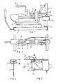
- Fig. 1 das Schweißgerät in Seitenansicht,
- Fig. 2 das SChweißgerät nach Fig. 1 in Draufsicht,
- Fig. 3 das Schweißgerät mit Temperaturregler,
- Fig. 4 einen Schnitt nach A-A der Fig. 3.
- Das Schweißgerät nach den Fig. 1 und 2 besteht aus einem Arbeitstisch (1), der aus zwei im Abstand nebeneinander angeordneten Tragholmen (2 und 3) zusammengesetzt sein kann. Der Arbeitstisch (1) weist eine Schlitzöffnung auf, in die ein Schweißschwert (4) einfahrbar ist.
- Das Schweißschwert (4) ist an einer Tragvorrichtung (5) mit Griff (6) angeordnet. An der Tragvorrichtung (5) sind zwei im Abstand etwa parallel zueinander angeordnete Haltestangen (7 und 8) darüber angelenkt, deren andere Enden (9 und 10) ebenfalls drehbar an dem lotrechten Ständer (11) gelagert sind. Der lotrechte Ständer (11) ist mit seinem unteren Ende am Arbeitstisch drehbar gelagert, so daß die Tragvorrichtung (5) mit dem Schweißschwert (4) seitlich ausschwenkbar ist. Am Parallelgestänge (7, 8) befindet sich eine Rückholfeder (12), deren anderes Ende mit dem lotrechten Ständer (11) verbunden ist.
- Durch Druck auf den Griff (6) läßt sich die Tragvorrichtung (5) und damit das Schweißschwert (4) in den Schlitz des Arbeitstisches (1) absenken, wobei durch die Parallelanordnung der Stangen (7 und 8) die untere Kante des Schweißschwertes (4) in paralleler Stellung verfahrbar ist.
- Um die Schwenkbewegung des lotrechten Ständers zu begrenzen, ist eine verstellbare Arretierschraube (13) am Ständer angeordnet. Am Ende des Schweißschwertes (4) ist ein Temperaturregler (14) angeordnet, dessen Gehäuse (15) wärmeisoliert ist. Hierzu sind die Befestigungsschrauben (16) in einer wärmeisolierenden Hülle (20) aus Teflon, Keramik od. dgl. angeordnet. Dies ist erforderlich, da die Schweißtemperatur 380° betragen kann, während der Regler nur eine Temperatur bis 70° störungsfrei annehmen kann.
- Wie in Fig. 4 erkennbar, hat das Schweißgerät (4) an seiner oberen Kante beidseitig je einen Heizstab (17 und 18). Jeder Heizstab ist in eine Hülse (19) einsteckbar, die mit der Schweißschwertoberkante verschweißt ist.
- Durch die beidseitige Anordnung von Heizstäben wird erreicht, daß das Schweißschwert keine einseitige Krümmung erfährt, wenn es unter Hitzeeinwirkung steht.
Claims (10)
Applications Claiming Priority (2)
| Application Number | Priority Date | Filing Date | Title |
|---|---|---|---|
| DE8810848U | 1988-08-27 | ||
| DE8810848U DE8810848U1 (de) | 1988-08-27 | 1988-08-27 | Schweißgerät zum Verbinden der Enden zweier Bänder aus thermoplastischem Material |
Publications (2)
| Publication Number | Publication Date |
|---|---|
| EP0356895A2 true EP0356895A2 (de) | 1990-03-07 |
| EP0356895A3 EP0356895A3 (de) | 1991-11-13 |
Family
ID=6827311
Family Applications (1)
| Application Number | Title | Priority Date | Filing Date |
|---|---|---|---|
| EP19890115524 Withdrawn EP0356895A3 (de) | 1988-08-27 | 1989-08-23 | Schweissgerät zum Verbinden der Enden zweier Bänder aus thermoplastischem Material |
Country Status (2)
| Country | Link |
|---|---|
| EP (1) | EP0356895A3 (de) |
| DE (1) | DE8810848U1 (de) |
Cited By (1)
| Publication number | Priority date | Publication date | Assignee | Title |
|---|---|---|---|---|
| CN111418942A (zh) * | 2020-04-02 | 2020-07-17 | 深圳威特尔自动化科技有限公司 | 一拖二全自动平面口罩机 |
Family Cites Families (10)
| Publication number | Priority date | Publication date | Assignee | Title |
|---|---|---|---|---|
| DE8109706U1 (de) * | 1982-01-07 | Bienek, Günter, 5500 Trier | Schweißgerät zum Verbinden der Enden zweier Bänder aus thermoplastischem Material | |
| FR1086334A (fr) * | 1953-07-08 | 1955-02-11 | Perfectionnements aux machines à souder les feuilles de polyethylène et analogues | |
| US2884395A (en) * | 1955-08-01 | 1959-04-28 | American Cyanamid Co | Quaternary ammonium hydroxide stabilized cationic amino-formaldehyde solution and process for making same |
| DE1202970B (de) * | 1959-12-18 | 1965-10-14 | Erwin Zuercher | Vorrichtung zum Stumpfschweissen von Werkstuecken aus thermoplastischem Material |
| DE1704109A1 (de) * | 1967-10-05 | 1971-04-22 | Huebers Elektromaschinen Kg | Steuerungsvorrichtung fuer einen Schweissspiegel und die Schweissgutstuecke einer Kunststoffschweissmaschine |
| US3586584A (en) * | 1968-10-28 | 1971-06-22 | Chester Wilkins | Automatic plastic welding machine |
| FR2154346B3 (de) * | 1971-09-27 | 1974-06-07 | Hadjian Levon | |
| DE2316748A1 (de) * | 1973-04-04 | 1974-10-17 | Wicolit Kunststoff Verarbeitun | Verfahren und vorrichtung zum stumpfschweissen von dehnungsfugenbaendern aus kunststoff |
| US3897296A (en) * | 1973-07-12 | 1975-07-29 | Amchem Prod | Thermal welding of plastic |
| US3902943A (en) * | 1974-08-19 | 1975-09-02 | Dow Chemical Co | Method and apparatus for joining plastic elements |
-
1988
- 1988-08-27 DE DE8810848U patent/DE8810848U1/de not_active Expired
-
1989
- 1989-08-23 EP EP19890115524 patent/EP0356895A3/de not_active Withdrawn
Cited By (1)
| Publication number | Priority date | Publication date | Assignee | Title |
|---|---|---|---|---|
| CN111418942A (zh) * | 2020-04-02 | 2020-07-17 | 深圳威特尔自动化科技有限公司 | 一拖二全自动平面口罩机 |
Also Published As
| Publication number | Publication date |
|---|---|
| EP0356895A3 (de) | 1991-11-13 |
| DE8810848U1 (de) | 1988-12-08 |
Similar Documents
| Publication | Publication Date | Title |
|---|---|---|
| DE2759598C2 (de) | Trennwandsystem aus mehreren aufrechten Wandelementen und Wandverbindungselementen | |
| DE69935744T2 (de) | Tischsäge | |
| DE202008014216U1 (de) | Vorrichtung zum thermischen Schneiden von Kunststoffkörpern | |
| DE2712651C2 (de) | Rahmenauflegestation in einer Anlage zum Zusammenbau von Isolierglas | |
| EP0356895A2 (de) | Schweissgerät zum Verbinden der Enden zweier Bänder aus thermoplastischem Material | |
| DE102014218789A1 (de) | Schneidgerät | |
| DE2809201A1 (de) | Kreissaegetisch, insbesondere fuer heimwerker | |
| DE3347920C2 (de) | Sägeeinrichtung | |
| CH678410A5 (de) | ||
| AT400546B (de) | Transportables gerät zum schneiden von platten aus weichem kunststoffmaterial | |
| DE2349329A1 (de) | Vorrichtung zum aufloeten eines stromanschlusselementes auf eine glasscheibe | |
| EP0199163B1 (de) | Bindegerät | |
| DE3304512C2 (de) | ||
| DE29800992U1 (de) | Thermische Schneidvorrichtung für Platten aus thermisch trennbarem Material | |
| DE2402420A1 (de) | Selbstarretierende stuetzvorrichtung | |
| DE3300619C2 (de) | Vorrichtung zum Querschneiden, Signieren und Kontrollieren von hängend angeordneten großflächigen Stoffbahnen | |
| DE9306314U1 (de) | Vorrichtung zum Zertrennen von Gitterrosten | |
| DE2018666B2 (de) | Zeichenplatte | |
| DE2754125C2 (de) | Erdungsvorrichtung | |
| DE102011079119B4 (de) | Schneidgerät zum Schmelzschneiden von Dämmplatten | |
| DE2506994A1 (de) | Anordnung zum schneiden von stoffteilen | |
| DE1427255B2 (de) | Schneid- und Preßvorrichtung | |
| DD235769A1 (de) | Halterung fuer elektrische geraete in gerasteter einschubtechnik | |
| DE3120125A1 (de) | Stuetzenhalter mit spreizbaren beinen fuer eine stuetze einer deckenschalung | |
| DE2717288A1 (de) | Vorrichtung zur halterung von arbeitsgeraetschaften |
Legal Events
| Date | Code | Title | Description |
|---|---|---|---|
| PUAI | Public reference made under article 153(3) epc to a published international application that has entered the european phase |
Free format text: ORIGINAL CODE: 0009012 |
|
| AK | Designated contracting states |
Kind code of ref document: A2 Designated state(s): AT BE CH DE ES FR GB GR IT LI LU NL SE |
|
| 17P | Request for examination filed |
Effective date: 19901228 |
|
| PUAL | Search report despatched |
Free format text: ORIGINAL CODE: 0009013 |
|
| AK | Designated contracting states |
Kind code of ref document: A3 Designated state(s): AT BE CH DE ES FR GB GR IT LI LU NL SE |
|
| RAP1 | Party data changed (applicant data changed or rights of an application transferred) |
Owner name: TRICOSAL GMBH |
|
| 17Q | First examination report despatched |
Effective date: 19930930 |
|
| STAA | Information on the status of an ep patent application or granted ep patent |
Free format text: STATUS: THE APPLICATION IS DEEMED TO BE WITHDRAWN |
|
| 18D | Application deemed to be withdrawn |
Effective date: 19940211 |