EP0356911A2 - Tuyau flexible pour le renouvellement de conduites, notamment d'égouts - Google Patents
Tuyau flexible pour le renouvellement de conduites, notamment d'égouts Download PDFInfo
- Publication number
- EP0356911A2 EP0356911A2 EP89115609A EP89115609A EP0356911A2 EP 0356911 A2 EP0356911 A2 EP 0356911A2 EP 89115609 A EP89115609 A EP 89115609A EP 89115609 A EP89115609 A EP 89115609A EP 0356911 A2 EP0356911 A2 EP 0356911A2
- Authority
- EP
- European Patent Office
- Prior art keywords
- hose
- rubber
- hose according
- plastic
- branch
- Prior art date
- Legal status (The legal status is an assumption and is not a legal conclusion. Google has not performed a legal analysis and makes no representation as to the accuracy of the status listed.)
- Granted
Links
Images





Classifications
-
- F—MECHANICAL ENGINEERING; LIGHTING; HEATING; WEAPONS; BLASTING
- F16—ENGINEERING ELEMENTS AND UNITS; GENERAL MEASURES FOR PRODUCING AND MAINTAINING EFFECTIVE FUNCTIONING OF MACHINES OR INSTALLATIONS; THERMAL INSULATION IN GENERAL
- F16L—PIPES; JOINTS OR FITTINGS FOR PIPES; SUPPORTS FOR PIPES, CABLES OR PROTECTIVE TUBING; MEANS FOR THERMAL INSULATION IN GENERAL
- F16L11/00—Hoses, i.e. flexible pipes
- F16L11/04—Hoses, i.e. flexible pipes made of rubber or flexible plastics
- F16L11/11—Hoses, i.e. flexible pipes made of rubber or flexible plastics with corrugated wall
- F16L11/112—Hoses, i.e. flexible pipes made of rubber or flexible plastics with corrugated wall having reinforcements embedded in the wall
-
- F—MECHANICAL ENGINEERING; LIGHTING; HEATING; WEAPONS; BLASTING
- F16—ENGINEERING ELEMENTS AND UNITS; GENERAL MEASURES FOR PRODUCING AND MAINTAINING EFFECTIVE FUNCTIONING OF MACHINES OR INSTALLATIONS; THERMAL INSULATION IN GENERAL
- F16L—PIPES; JOINTS OR FITTINGS FOR PIPES; SUPPORTS FOR PIPES, CABLES OR PROTECTIVE TUBING; MEANS FOR THERMAL INSULATION IN GENERAL
- F16L55/00—Devices or appurtenances for use in, or in connection with, pipes or pipe systems
- F16L55/16—Devices for covering leaks in pipes or hoses, e.g. hose-menders
- F16L55/162—Devices for covering leaks in pipes or hoses, e.g. hose-menders from inside the pipe
- F16L55/165—Devices for covering leaks in pipes or hoses, e.g. hose-menders from inside the pipe a pipe or flexible liner being inserted in the damaged section
- F16L55/1652—Devices for covering leaks in pipes or hoses, e.g. hose-menders from inside the pipe a pipe or flexible liner being inserted in the damaged section the flexible liner being pulled into the damaged section
-
- F—MECHANICAL ENGINEERING; LIGHTING; HEATING; WEAPONS; BLASTING
- F16—ENGINEERING ELEMENTS AND UNITS; GENERAL MEASURES FOR PRODUCING AND MAINTAINING EFFECTIVE FUNCTIONING OF MACHINES OR INSTALLATIONS; THERMAL INSULATION IN GENERAL
- F16L—PIPES; JOINTS OR FITTINGS FOR PIPES; SUPPORTS FOR PIPES, CABLES OR PROTECTIVE TUBING; MEANS FOR THERMAL INSULATION IN GENERAL
- F16L55/00—Devices or appurtenances for use in, or in connection with, pipes or pipe systems
- F16L55/16—Devices for covering leaks in pipes or hoses, e.g. hose-menders
- F16L55/162—Devices for covering leaks in pipes or hoses, e.g. hose-menders from inside the pipe
- F16L55/165—Devices for covering leaks in pipes or hoses, e.g. hose-menders from inside the pipe a pipe or flexible liner being inserted in the damaged section
- F16L55/1656—Devices for covering leaks in pipes or hoses, e.g. hose-menders from inside the pipe a pipe or flexible liner being inserted in the damaged section materials for flexible liners
-
- F—MECHANICAL ENGINEERING; LIGHTING; HEATING; WEAPONS; BLASTING
- F16—ENGINEERING ELEMENTS AND UNITS; GENERAL MEASURES FOR PRODUCING AND MAINTAINING EFFECTIVE FUNCTIONING OF MACHINES OR INSTALLATIONS; THERMAL INSULATION IN GENERAL
- F16L—PIPES; JOINTS OR FITTINGS FOR PIPES; SUPPORTS FOR PIPES, CABLES OR PROTECTIVE TUBING; MEANS FOR THERMAL INSULATION IN GENERAL
- F16L55/00—Devices or appurtenances for use in, or in connection with, pipes or pipe systems
- F16L55/16—Devices for covering leaks in pipes or hoses, e.g. hose-menders
- F16L55/179—Devices for covering leaks in pipes or hoses, e.g. hose-menders specially adapted for bends, branch units, branching pipes or the like
Definitions
- the invention relates to a hose for the rehabilitation of pipelines, in particular sewers, according to the preamble of claim 1.
- short pipes With short pipe relining, short pipes can be pushed together in the inspection shafts and sealed with each other using sealing rings made of Perbunan or EPDM. After connecting a new short pipe, it is inserted or pulled into the defective duct. Weak points are the large number of pipe connections, each of which can be leaky due to shape or design errors. In addition, no change of direction in the pipe is possible.
- HDPE high-density polyethylene
- duct construction pits earthworks
- the HDPE pipes are drawn into the defective duct via these construction pits.
- the disadvantage of the process lies in the often disruptive and cost-intensive underground pits. In addition, no change of direction in the pipe is possible.
- a prefabricated fiber felt tube soaked with curable materials (resin) is inserted into the defective pipeline and, depending on the curing material, hardened.
- the inserted fiber felt hose is pressed against the inner wall of the pipeline to be renovated using a calibration hose with water pressure.
- the resin By curing the resin, the hose becomes a tube.
- the disadvantage of the process is the restrained connection of the two inner tubes due to the unevenness of the defective tube. In the event of a later need For further maintenance, the inner tube cannot be removed or only with great effort. The homogeneous quality of the inner tube is also difficult to test.
- the tubular lining material made of textile material is applied to the inner surface of the pipeline with the aid of a binder (adhesive) (DE-OS 34 14 531 and 35 05 107; GB-PS 10 02 131, 10 25 011 and 10 69 623; U.S. Patents 27 94 785, 31 32 062, 32 30 129 and 34 94 813).
- a binder adheresive
- a particular disadvantage here is that the amount and distribution of the binder cannot be controlled, so that it may be applied non-uniformly.
- the large number of publications illustrate the problems with this lining process.
- a common disadvantage of the remediation methods presented here is that a longer business interruption is inevitable. This applies in particular to process variants 4 and 5, in which the use of resin or binders makes it necessary to completely dry the waste water pipes to be renovated. Since companies in the industrial sector want to continuously discharge waste water, the time factor for an interruption plays a decisive role.
- the object of the invention is to provide a hose for the rehabilitation of pipelines, in particular sewers, which can be drawn in easily, quickly and with little downtime, and which adapts to any pipe bend without causing a problem in pipe rehabilitation in this area Cross section of the hose comes from kinking.
- the hose must be extractable for repair purposes so that it can be replaced without much effort.
- Such a hose is thus highly flexible, since it adapts to the changes of direction (in the form of angled bends) of up to 45 ° which are common in the pipeline network.
- the spiral hose according to the invention is suitable for vacuum use. - Because of its high flexibility, it is possible to align the hose to the required rehabilitation length immediately after its manufacture, once the dimensions of the pipeline network to be rehabilitated are known. In the event that the production length is less than the length of the pipe to be renovated, individual hose sections are extended to a transportable size with the aid of a short plastic pipe adapter which is adhesively connected to the inner wall of the hose.
- a further extension can be carried out on site before the hose is pulled in by connecting short plastic pipes, which are an integrated end part of the hose sections (for example by welding).
- short plastic pipes which are an integrated end part of the hose sections (for example by welding).
- the importance of these plastic pipes, especially in the manufacture of the branch, will be discussed in detail later.
- the highly flexible hose can be floated in. In many cases, the sewer can remain in operation while it is being drawn in. Depending on the line conditions, the hose pulling operation can be completed in less than 60 minutes. No expensive and complicated special machines are required for this operation. A complete or partial business interruption is therefore limited to procedural measures that are associated with the production of a branch and the connections (eg shaft and operating connections).
- the hose of rubber or rubber-like material according to the invention allows the use of different qualities that are adapted to the chemical or thermal loads.
- a suitable hose material is, for example, a rubber mixture based on polychloroprene (Baypren).
- Subclaims 22 to 34 deal with expedient methods for hose extension, for pulling the hose and for the production of connections and branches.
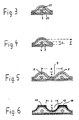
- the highly flexible hose (1) consists of the core (2) and the ceiling (3), between which the spiral wire (4) and the wave-shaped pressure carrier (5) made of textile material are embedded as reinforcing elements.
- the pressure carrier (5) is at its lowest point (6) with the hose core (2) in direct connection.
- the one-piece padding (7), in which the spiral wire (4) is embedded in the immediate vicinity of the hose core (2), is located between the hose core (2) and the pressure carrier (5).
- the hose cover (3) itself is designed as a rib-groove system, the ribs (8) being arranged in the region of the pressure carrier elevations (10) and the grooves (9) in the region of the pressure carrier recesses (11).
- the hose (12) according to FIG. 2 with core (13), cover (14), spiral wire (15), pressure carrier (16) and padding (17) differs from that according to FIG. 1 only in that the ribs (18 ) are crown-shaped and the grooves (19) are arcuate.
- Fig. 3 shows a two-piece padding.
- Both the inner and the outer padding are expediently made of rubber or rubber-like material, the hardness in Shore A of the inner padding (20) being 30 to 50 and that of the outer padding (21) being 70 or more.
- the spiral wire (4) is embedded in the inner padding (20).
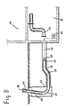
- a hose (22) is inserted into the inspection shaft (23) and pulled through the pipe (26) to be renovated with the aid of a pull tab (24) and a rotating body (25).
- Three changes of direction are illustrated in the context of this FIG. in the area of the inspection shaft (23) with the hose bend (27) of approximately 90 ° and within the tube (26) with the hose bends (28, 29) each with approximately 45 °.
- the hose construction according to the invention - not shown here - it is achieved that the hose itself is stable in cross section at the points of curvature (27, 28, 29). This ensures a constant flow cross-section.
- the hose (22) has flanges (30, 31) at its ends, the flange (31) being made of a highly flexible material.
- the flange (31) While pulling the hose through the pipe, the flange (31) is turned inside.
- the flange (31) is later connected to the service connection (32), which is located here in the basement (33) of the building (34).
- the flange (30) is attached to the shaft wall (35).
- a hose is shown which is formed in one piece over the entire renovation length. Often however, it is necessary that individual hose sections are connected to each other with the help of a short piece of pipe because of the limited manufacturing length.
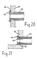
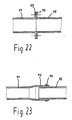
- a plastic tube (36) which expediently consists of PE, PU, ABS or fluorine-containing plastic and which is adhesively connected to the inner wall of the hose ends (37, 43), etc. especially through vulcanization.
- the entire adhesive system (38) is formed here in two layers, etc. in the form of the inner layer (39), which consists of a non-crosslinked film (e.g. polyethylene film when using a PE pipe), and the overlying layer (40) made of rubber (eg EPDM, SBR, NBR, H-NBR, CR, BR, CSM, FKM, EVA, NR, IR, IIR, ClIIR, BrIIR, blends of these rubber types).
- a non-crosslinked film e.g. polyethylene film when using a PE pipe
- the overlying layer (40) made of rubber (eg EPDM, SBR, NBR, H-NBR, CR, BR, CSM, FKM, EVA, NR, IR, IIR, Cl
- the plastic tube (36) is designed so that in the transition area (41) there is a continuous surface formation of the plastic tube and the hose cover (42).
- the plastic pipe can be used as a finished intermediate piece to connect hose sections to one another immediately after their manufacture.
- the lengthening of the hoses can also take place in that two plastic pipes as the respective end pieces of the hose sections to be connected on site, i.e. welded together before pulling the hose into the pipeline to be renovated.
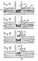
- Fig. 11 shows a sewer (44) with a tap (45).
- a plastic pipe intermediate piece is worked into the length of the hose. This tube is adhesively connected to the hose.
- the hose which is composed of the hose sections (46, 47), is drawn into the defective pipeline.
- the plastic pipe (48) comes to rest exactly on the tap (45) (Fig. 13).
- the position is checked with appropriate sensors. With a special tool, a hole (49) is made in the tube (48) in the correct position (FIG. 14).
- the second hose (50) is then drawn into the branch (45), the hose being provided with a plastic tube (51) at the tip (FIG. 15).
- the hose (50) is drawn in until the plastic tube (51) protrudes into the plastic tube intermediate piece (48) (Fig. 16).
- the method of variant B is mainly used for heavy soiling and flowing dirt.
Landscapes
- Engineering & Computer Science (AREA)
- General Engineering & Computer Science (AREA)
- Mechanical Engineering (AREA)
- Rigid Pipes And Flexible Pipes (AREA)
Priority Applications (1)
| Application Number | Priority Date | Filing Date | Title |
|---|---|---|---|
| AT89115609T ATE83543T1 (de) | 1988-08-26 | 1989-08-24 | Schlauch zur sanierung von rohrleitungen, insbesondere von abwasserkanaelen. |
Applications Claiming Priority (8)
| Application Number | Priority Date | Filing Date | Title |
|---|---|---|---|
| DE3828972 | 1988-08-26 | ||
| DE3828972 | 1988-08-26 | ||
| DE3841204 | 1988-12-07 | ||
| DE3841204 | 1988-12-07 | ||
| DE3912467 | 1989-04-15 | ||
| DE3912467 | 1989-04-15 | ||
| DE3923697 | 1989-07-18 | ||
| DE3923697 | 1989-07-18 |
Publications (3)
| Publication Number | Publication Date |
|---|---|
| EP0356911A2 true EP0356911A2 (fr) | 1990-03-07 |
| EP0356911A3 EP0356911A3 (en) | 1990-03-28 |
| EP0356911B1 EP0356911B1 (fr) | 1992-12-16 |
Family
ID=27434325
Family Applications (1)
| Application Number | Title | Priority Date | Filing Date |
|---|---|---|---|
| EP89115609A Expired - Lifetime EP0356911B1 (fr) | 1988-08-26 | 1989-08-24 | Tuyau flexible pour le renouvellement de conduites, notamment d'égouts |
Country Status (4)
| Country | Link |
|---|---|
| EP (1) | EP0356911B1 (fr) |
| DE (1) | DE58903015D1 (fr) |
| ES (1) | ES2037922T3 (fr) |
| GR (1) | GR3007184T3 (fr) |
Cited By (5)
| Publication number | Priority date | Publication date | Assignee | Title |
|---|---|---|---|---|
| WO1993023697A1 (fr) * | 1992-05-14 | 1993-11-25 | Hans Valter Norberg | Joint d'etancheite dilatable, procede et outillage pour le montage de ce joint |
| EP0533116A3 (en) * | 1991-09-20 | 1995-03-29 | Phoenix Ag | Pressure hose |
| DE19508188A1 (de) * | 1995-03-09 | 1996-09-12 | Trolining Gmbh | Hutförmige Anschlußmanschette für Hausanschlüsse in Kanalrohren |
| WO2004013535A1 (fr) * | 2002-08-03 | 2004-02-12 | Peter James Boatman | Tuyau combine et procede de reparation de tuyaux |
| DE102005019449A1 (de) * | 2005-04-25 | 2006-10-26 | Bodenbender Gmbh | Formteil und Sanierungsverfahren |
Families Citing this family (1)
| Publication number | Priority date | Publication date | Assignee | Title |
|---|---|---|---|---|
| DE59307186D1 (de) | 1992-04-23 | 1997-10-02 | Phoenix Ag | Sicherheitsschlauch |
Family Cites Families (7)
| Publication number | Priority date | Publication date | Assignee | Title |
|---|---|---|---|---|
| US3047026A (en) * | 1959-09-23 | 1962-07-31 | Acme Hamilton Mfg Corp | Flexible hose |
| CH457056A (it) * | 1967-05-18 | 1968-05-31 | S Tubi Gomma Torino Sa | Tubo in gomma con tele e filo metallico ad andamento elicoidale incorporati, per mandata e aspirazione di aria, di liquidi, di cereali e simili |
| DE2263368A1 (de) * | 1972-12-23 | 1974-06-27 | Continental Gummi Werke Ag | Biegsamer schlauch |
| GB2041147B (en) * | 1979-01-22 | 1982-12-15 | Fusion Equipment Ltd | Renovating sewers |
| DE3129870A1 (de) * | 1981-07-29 | 1983-02-17 | Günter 5400 Koblenz Rogalski | Verfahren zum instandsetzen von im erdreich verlegten rohrleitungssystemen und vorrichtung zur durchfuehrung des verfahrens |
| NL8502327A (nl) * | 1985-08-23 | 1987-03-16 | Wavin Bv | Kunststofbuis bestaande uit een buitenhuis met ribbels en gladde binnenwand, alsmede werkwijze voor het herstellen resp. verbeteren van een rioleringsbuis. |
| SE8600964L (sv) * | 1986-03-04 | 1987-09-05 | Uponor Ab | Ror for infodring av markforlagda rorledningar |
-
1989
- 1989-08-24 EP EP89115609A patent/EP0356911B1/fr not_active Expired - Lifetime
- 1989-08-24 ES ES198989115609T patent/ES2037922T3/es not_active Expired - Lifetime
- 1989-08-24 DE DE8989115609T patent/DE58903015D1/de not_active Expired - Fee Related
-
1993
- 1993-02-26 GR GR930400423T patent/GR3007184T3/el unknown
Cited By (5)
| Publication number | Priority date | Publication date | Assignee | Title |
|---|---|---|---|---|
| EP0533116A3 (en) * | 1991-09-20 | 1995-03-29 | Phoenix Ag | Pressure hose |
| WO1993023697A1 (fr) * | 1992-05-14 | 1993-11-25 | Hans Valter Norberg | Joint d'etancheite dilatable, procede et outillage pour le montage de ce joint |
| DE19508188A1 (de) * | 1995-03-09 | 1996-09-12 | Trolining Gmbh | Hutförmige Anschlußmanschette für Hausanschlüsse in Kanalrohren |
| WO2004013535A1 (fr) * | 2002-08-03 | 2004-02-12 | Peter James Boatman | Tuyau combine et procede de reparation de tuyaux |
| DE102005019449A1 (de) * | 2005-04-25 | 2006-10-26 | Bodenbender Gmbh | Formteil und Sanierungsverfahren |
Also Published As
| Publication number | Publication date |
|---|---|
| GR3007184T3 (fr) | 1993-07-30 |
| DE58903015D1 (de) | 1993-01-28 |
| ES2037922T3 (es) | 1993-07-01 |
| EP0356911B1 (fr) | 1992-12-16 |
| EP0356911A3 (en) | 1990-03-28 |
Similar Documents
| Publication | Publication Date | Title |
|---|---|---|
| EP0499153B1 (fr) | Procédé pour la restauration partielle d'un égout enterré | |
| EP0405163B1 (fr) | Tuyaux en matières plastiques pour rénovation de canalisations | |
| EP0475309A1 (fr) | Dispositif et procédé d'assainissement pour assainir des tuyaux de canalisation | |
| DE4238982C2 (de) | Auskleideschlauch zum Sanieren unterirdisch verlegter Abwasserkanäle, Rohrleitungen o. dgl. | |
| EP0356911B1 (fr) | Tuyau flexible pour le renouvellement de conduites, notamment d'égouts | |
| DE3927961A1 (de) | Schlauch zur sanierung von rohrleitungen, insbesondere von abwasserkanaelen | |
| EP1090448A1 (fr) | Procede pour installer au moins une conduite et/ou un tuyau vide dans des tuyaux poses servant a l'alimentation ou a l'elimination, notamment dans des systemes ou des reseaux de canalisations tubulaires | |
| DE20108163U1 (de) | Rohrsystem | |
| DE3931775A1 (de) | Geraet zum beschichten von innenflaechen einer abwasserrohrleitung | |
| EP0932794A1 (fr) | Appareil de renovation de canalisations | |
| DE102006034652B4 (de) | Packer für die Rohr- und Kanalsanierung | |
| DE19826155A1 (de) | Verfahren und Einrichtung zum Sanieren unbegehbarer Rohre, insbesondere Abwasserrohre | |
| WO2008000474A2 (fr) | Dispositif et procédé de mise en place facile d'un tuyau long en matière plastique dans un conduit via un puits | |
| EP0677690B1 (fr) | Etanchement de l'embout d'un manchon | |
| DE69808850T2 (de) | Vorrichtung zum Orten des Eintritts einer Abzweigrohrleitung und Rohrauskleidungsverfahren unter Verwendung dieser Vorrichtung | |
| EP0436060B1 (fr) | Procédé de gainage d'enceintes, notamment pour la restauration des conduites endommagées | |
| AT404500B (de) | Einsatzteil und verfahren zum sanieren der undichten wände von leitungen unter verwendung eines solchen einsatzteiles | |
| DE102009012613B4 (de) | Verfahren und Vorrichtung zum Einbringen eines Rohrs in eine Bohrung im Erdreich | |
| DE102009053319A1 (de) | Anordnung zum Sanieren schadhafter Rohrleitungen eines Kanalnetzes | |
| EP1837576A1 (fr) | Dispositif de fabrication d'un agencement d'étanchéité pour tuyaux et constructions de puits | |
| DE102019110627A1 (de) | Rohrmodul zur Ableitung von Abwasser, Trennsystem mit dem Rohrmodul sowie Verfahren zur Herstellung des Rohrmoduls | |
| DE202019102308U1 (de) | Rohrmodul zur Ableitung von Abwasser, Trennsystem mit dem Rohrmodul sowie Verlegeroboter | |
| EP0550860A1 (fr) | Assemblage de garniture | |
| EP0300169A1 (fr) | Coussin de joint pour tuyaux avec passage | |
| DE102008063007A1 (de) | Blähpacker zur Durchführung einer grabenlosen Reparatur von Schadstellen in Rohrleitungen |
Legal Events
| Date | Code | Title | Description |
|---|---|---|---|
| PUAI | Public reference made under article 153(3) epc to a published international application that has entered the european phase |
Free format text: ORIGINAL CODE: 0009012 |
|
| PUAL | Search report despatched |
Free format text: ORIGINAL CODE: 0009013 |
|
| AK | Designated contracting states |
Kind code of ref document: A2 Designated state(s): AT BE CH DE ES FR GB GR IT LI NL SE |
|
| AK | Designated contracting states |
Kind code of ref document: A3 Designated state(s): AT BE CH DE ES FR GB GR IT LI NL SE |
|
| GBC | Gb: translation of claims filed (gb section 78(7)/1977) | ||
| 17P | Request for examination filed |
Effective date: 19900419 |
|
| 17Q | First examination report despatched |
Effective date: 19910125 |
|
| GRAA | (expected) grant |
Free format text: ORIGINAL CODE: 0009210 |
|
| AK | Designated contracting states |
Kind code of ref document: B1 Designated state(s): AT BE CH DE ES FR GB GR IT LI NL SE |
|
| REF | Corresponds to: |
Ref document number: 83543 Country of ref document: AT Date of ref document: 19930115 Kind code of ref document: T |
|
| REF | Corresponds to: |
Ref document number: 58903015 Country of ref document: DE Date of ref document: 19930128 |
|
| ET | Fr: translation filed | ||
| ITF | It: translation for a ep patent filed | ||
| GBT | Gb: translation of ep patent filed (gb section 77(6)(a)/1977) |
Effective date: 19930301 |
|
| REG | Reference to a national code |
Ref country code: GR Ref legal event code: FG4A Free format text: 3007184 |
|
| REG | Reference to a national code |
Ref country code: ES Ref legal event code: FG2A Ref document number: 2037922 Country of ref document: ES Kind code of ref document: T3 |
|
| PLBE | No opposition filed within time limit |
Free format text: ORIGINAL CODE: 0009261 |
|
| STAA | Information on the status of an ep patent application or granted ep patent |
Free format text: STATUS: NO OPPOSITION FILED WITHIN TIME LIMIT |
|
| 26N | No opposition filed | ||
| PGFP | Annual fee paid to national office [announced via postgrant information from national office to epo] |
Ref country code: GB Payment date: 19940706 Year of fee payment: 6 |
|
| PGFP | Annual fee paid to national office [announced via postgrant information from national office to epo] |
Ref country code: GR Payment date: 19940727 Year of fee payment: 6 Ref country code: CH Payment date: 19940727 Year of fee payment: 6 |
|
| PGFP | Annual fee paid to national office [announced via postgrant information from national office to epo] |
Ref country code: AT Payment date: 19940801 Year of fee payment: 6 |
|
| PGFP | Annual fee paid to national office [announced via postgrant information from national office to epo] |
Ref country code: BE Payment date: 19940810 Year of fee payment: 6 |
|
| PGFP | Annual fee paid to national office [announced via postgrant information from national office to epo] |
Ref country code: ES Payment date: 19940822 Year of fee payment: 6 |
|
| PGFP | Annual fee paid to national office [announced via postgrant information from national office to epo] |
Ref country code: SE Payment date: 19940831 Year of fee payment: 6 Ref country code: NL Payment date: 19940831 Year of fee payment: 6 Ref country code: FR Payment date: 19940831 Year of fee payment: 6 |
|
| EAL | Se: european patent in force in sweden |
Ref document number: 89115609.3 |
|
| PG25 | Lapsed in a contracting state [announced via postgrant information from national office to epo] |
Ref country code: GB Effective date: 19950824 Ref country code: AT Effective date: 19950824 |
|
| PG25 | Lapsed in a contracting state [announced via postgrant information from national office to epo] |
Ref country code: SE Effective date: 19950825 Ref country code: ES Free format text: LAPSE BECAUSE OF EXPIRATION OF PROTECTION Effective date: 19950825 |
|
| PG25 | Lapsed in a contracting state [announced via postgrant information from national office to epo] |
Ref country code: LI Effective date: 19950831 Ref country code: CH Effective date: 19950831 Ref country code: BE Effective date: 19950831 |
|
| PG25 | Lapsed in a contracting state [announced via postgrant information from national office to epo] |
Ref country code: GR Free format text: THE PATENT HAS BEEN ANNULLED BY A DECISION OF A NATIONAL AUTHORITY Effective date: 19960228 |
|
| BERE | Be: lapsed |
Owner name: PHOENIX A.G. Effective date: 19950831 Owner name: BAYER A.G. Effective date: 19950831 |
|
| PG25 | Lapsed in a contracting state [announced via postgrant information from national office to epo] |
Ref country code: NL Effective date: 19960301 |
|
| REG | Reference to a national code |
Ref country code: CH Ref legal event code: PL |
|
| GBPC | Gb: european patent ceased through non-payment of renewal fee |
Effective date: 19950824 |
|
| PG25 | Lapsed in a contracting state [announced via postgrant information from national office to epo] |
Ref country code: FR Effective date: 19960430 |
|
| REG | Reference to a national code |
Ref country code: GR Ref legal event code: MM2A Free format text: 3007184 |
|
| NLV4 | Nl: lapsed or anulled due to non-payment of the annual fee |
Effective date: 19960301 |
|
| EUG | Se: european patent has lapsed |
Ref document number: 89115609.3 |
|
| REG | Reference to a national code |
Ref country code: FR Ref legal event code: ST |
|
| PGFP | Annual fee paid to national office [announced via postgrant information from national office to epo] |
Ref country code: DE Payment date: 19960813 Year of fee payment: 8 |
|
| PG25 | Lapsed in a contracting state [announced via postgrant information from national office to epo] |
Ref country code: DE Free format text: LAPSE BECAUSE OF NON-PAYMENT OF DUE FEES Effective date: 19980501 |
|
| REG | Reference to a national code |
Ref country code: ES Ref legal event code: FD2A Effective date: 19990601 |
|
| PG25 | Lapsed in a contracting state [announced via postgrant information from national office to epo] |
Ref country code: IT Free format text: LAPSE BECAUSE OF NON-PAYMENT OF DUE FEES;WARNING: LAPSES OF ITALIAN PATENTS WITH EFFECTIVE DATE BEFORE 2007 MAY HAVE OCCURRED AT ANY TIME BEFORE 2007. THE CORRECT EFFECTIVE DATE MAY BE DIFFERENT FROM THE ONE RECORDED. Effective date: 20050824 |