EP0357078A2 - Lampe électrique à filament à incandescence spiralé et moyens pour limiter les mouvements du filament - Google Patents
Lampe électrique à filament à incandescence spiralé et moyens pour limiter les mouvements du filament Download PDFInfo
- Publication number
- EP0357078A2 EP0357078A2 EP89116148A EP89116148A EP0357078A2 EP 0357078 A2 EP0357078 A2 EP 0357078A2 EP 89116148 A EP89116148 A EP 89116148A EP 89116148 A EP89116148 A EP 89116148A EP 0357078 A2 EP0357078 A2 EP 0357078A2
- Authority
- EP
- European Patent Office
- Prior art keywords
- filament
- lamp
- envelope
- lead
- support
- Prior art date
- Legal status (The legal status is an assumption and is not a legal conclusion. Google has not performed a legal analysis and makes no representation as to the accuracy of the status listed.)
- Granted
Links
- 229910052736 halogen Inorganic materials 0.000 claims description 9
- 150000002367 halogens Chemical class 0.000 claims description 3
- 230000001154 acute effect Effects 0.000 claims 4
- 210000003963 intermediate filament Anatomy 0.000 abstract description 24
- 239000011521 glass Substances 0.000 abstract description 8
- 238000004804 winding Methods 0.000 abstract description 7
- 238000000926 separation method Methods 0.000 abstract description 6
- 230000002028 premature Effects 0.000 abstract description 4
- 238000000034 method Methods 0.000 abstract description 2
- 238000007665 sagging Methods 0.000 abstract 1
- ZOKXTWBITQBERF-UHFFFAOYSA-N Molybdenum Chemical compound [Mo] ZOKXTWBITQBERF-UHFFFAOYSA-N 0.000 description 9
- 229910052721 tungsten Inorganic materials 0.000 description 8
- 239000010937 tungsten Substances 0.000 description 8
- -1 tungsten halogen Chemical class 0.000 description 7
- 229910052750 molybdenum Inorganic materials 0.000 description 5
- 239000011733 molybdenum Substances 0.000 description 5
- 230000035939 shock Effects 0.000 description 4
- 230000000694 effects Effects 0.000 description 3
- CPELXLSAUQHCOX-UHFFFAOYSA-N Hydrogen bromide Chemical compound Br CPELXLSAUQHCOX-UHFFFAOYSA-N 0.000 description 2
- PXHVJJICTQNCMI-UHFFFAOYSA-N Nickel Chemical compound [Ni] PXHVJJICTQNCMI-UHFFFAOYSA-N 0.000 description 2
- 238000005452 bending Methods 0.000 description 2
- 238000004519 manufacturing process Methods 0.000 description 2
- 238000004513 sizing Methods 0.000 description 2
- WFKWXMTUELFFGS-UHFFFAOYSA-N tungsten Chemical compound [W] WFKWXMTUELFFGS-UHFFFAOYSA-N 0.000 description 2
- 229910000831 Steel Inorganic materials 0.000 description 1
- 229910000323 aluminium silicate Inorganic materials 0.000 description 1
- 239000005354 aluminosilicate glass Substances 0.000 description 1
- 230000009286 beneficial effect Effects 0.000 description 1
- 230000015572 biosynthetic process Effects 0.000 description 1
- 239000005388 borosilicate glass Substances 0.000 description 1
- 238000006243 chemical reaction Methods 0.000 description 1
- 238000010276 construction Methods 0.000 description 1
- 238000001816 cooling Methods 0.000 description 1
- 230000007423 decrease Effects 0.000 description 1
- 230000007812 deficiency Effects 0.000 description 1
- 230000003467 diminishing effect Effects 0.000 description 1
- HNPSIPDUKPIQMN-UHFFFAOYSA-N dioxosilane;oxo(oxoalumanyloxy)alumane Chemical compound O=[Si]=O.O=[Al]O[Al]=O HNPSIPDUKPIQMN-UHFFFAOYSA-N 0.000 description 1
- 230000005484 gravity Effects 0.000 description 1
- 229910000042 hydrogen bromide Inorganic materials 0.000 description 1
- 239000011261 inert gas Substances 0.000 description 1
- 238000003780 insertion Methods 0.000 description 1
- 230000037431 insertion Effects 0.000 description 1
- 239000000463 material Substances 0.000 description 1
- 238000012986 modification Methods 0.000 description 1
- 230000004048 modification Effects 0.000 description 1
- 229910052759 nickel Inorganic materials 0.000 description 1
- 238000003825 pressing Methods 0.000 description 1
- 238000005096 rolling process Methods 0.000 description 1
- 238000007493 shaping process Methods 0.000 description 1
- 239000010959 steel Substances 0.000 description 1
- 238000003466 welding Methods 0.000 description 1
Images

Classifications
-
- H—ELECTRICITY
- H01—ELECTRIC ELEMENTS
- H01K—ELECTRIC INCANDESCENT LAMPS
- H01K1/00—Details
- H01K1/18—Mountings or supports for the incandescent body
Definitions
- This invention relates to electric lamps employing a coiled incandescent filament and more particularly to such lamps having filament movement restraint devices or intermediate filament supports to reduce or eliminate the possibility of the filament touching a lead-in wire or one point of a filament touching another point of the filament due to excessive filament movement.
- premature lamp failure may occur as a result of the operating filament coming into contact with the glass wall.
- the thermal shock imparted by the hot filament may crack the glass envelope and cause lamp failure, possibly a violent failure.
- the effect of gravity on a coiled filament may also give rise to premature lamp failure via shorting the filament or thermal shocking the glass envelope.
- the filament When mounted horizontally, the filament has a catenary shape between filament supports. If jostled sufficiently, the middle section of an operating filament may come in contact with a lead-in wire or the envelope wall. When mounted vertically, numerous turns of filamentary coil may bunch near the lower end of the filament. If jostled sufficiently, a number of coil turns of an operating filament may come into electrical contact with each other resulting in a shorting of the filament.
- filament sway or sag increases in severity as the length of the coiled filament increases and the diameter of the filamentary wire decreases.
- design length and wire diameter of the filament are rather narrowly constrained.
- filaments having design operating voltages of two hundred volts or higher e.g., lamps for use in many European countries
- commercially feasible filaments necessitate longer filaments with equivalent or thinner diameters than required in their lower voltage counterparts. Accordingly, additional or intermediate filament supports are commonly employed where filament sway or sag is a concern.
- an intermediate filament support is not without certain disadvantages, particularly with multiple coil filaments.
- an intermediate support is a hook or loop of wire having significantly more mass than the filamentary wire; the support hooks or grasps the filament. Mounting a filament on the heavier support may distend the filament turns near the mount. The relatively thick support wire may electrically short out two or three outermost turns of the filament, which may shorten the life of the filament. The more massive support may cool the filament appreciably in the vicinity of the mount which in turn may affect beneficial chemical reactions, such as the tungsten halogen cycle, between the operating filament and its environment.
- a loop of wire surrounding but not touching the filament has been employed as an intermediate support. While this type of support may restrain filament movement outside of the loop's perimeter, it does not deter movement along the filament's axis.
- the Martin patent United States Patent No. 3,930,177, issued December 30, 1975, shows an hook-type intermediate filament support which is mounted in a glass bridge within the lamp's envelope.
- an electric lamp comprising a light-transmissive envelope hermetically enclosing an interior.
- the envelope has a press seal formed in one end.
- first and second electrical lead-in wires protruding into the interior of the arc tube. These lead-in wires provide means for supplying electrical power from an external source within the lamp envelope.
- a coiled incandescent filament having a design operating voltage is mounted within the envelope.
- the filament has a central axis, a body, and two opposed ends.
- the body is formed from filamentary wire shaped in a helical coil with a plurality of turns about the central axis. The first end is electrically coupled with the first lead-in wire and the second end is electrically coupled with the second lead-in wire.
- the restraint means includes at least one flat section interposed between two adjacent turns of the filamentary coil.
- the flat section has a maximum thickness which is less than the distance between the two adjacent turns.
- the lamp is identical with that described in the first aspect of the invention except that the filament is a coiled coil filament, the flat section of the restraint means is interposed between adjacent turns of the second coil, and the maximum thickness of the flat section of the restraint means is less than the distance between the adjacent turns of the second coil.
- the lamp is identical with that described in the second aspect of the invention except that the filament is a coiled coiled coil filament, the flat section of the restraint means is interposed between adjacent turns of the third coil, and the maximum thickness of the flat section of the restraint means is less than the distance between the adjacent turns of the third coil.
- a coiled filament e.g., filament sway or sag
- an intermediate filament support, or filament movement restraint means which interposes a flat segment between adjacent turns of the outermost coil of the filament.
- a "coiled" filament includes a filament having a single, double, or triple coil. The maximum thickness of the flat segment is less than the distance between adjacent turns of the outermost coil. Use of the flat segment substantially reduces one or more of the various disadvantages associated with typical intermediate filament supports of the prior art.
- An intermediate support in accordance with the invention is relatively simple to manufacture and install so that its use does not increase the price of the lamp.
- the flat segment of the support is thinner than the distance between adjacent turns of the outermost coil of the filament, its insertion between the adjacent turns does not distort the outermost coil when the filament is mounted on or within the support.
- electrical contact is made between the flat segment and the energized filament, at most two adjacent outermost turns of the filament are shorted by the segment.
- the flat segment has equivalent or less cooling effect on the filament in the vicinity of the mount than does its cylindrical wire counterparts.
- the flat segment prevents any significant filament movement along the central axis of the filament.
- the support may encircle or grasp an inner coil of the filament (or the filamentary wire in the case of a filament with a single coil) so that filament movement in directions normal to the central axis of the filament may also be effectively restrained.
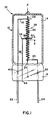
- FIG. 1 is an elevational view of a preferred embodiment of the invention.
- Lamp 10 comprises a single ended tungsten halogen lamp having a coiled coil filament with an intermediate filament support in accordance with the invention mounted in the press seal.
- lamp 10 is a low-wattage lamp, meaning that the rated wattage is one hundred and seventy-five watts or less.
- lamp 10 includes light transmissive envelope 12 hermetically enclosing interior 14 with press seal 16 formed in one end.
- Envelope 12 may preferably be formed from a hard glass, such as aluminosilicate or borosilicate glass.
- envelope 12 is single ended; however, the invention applies equally to double ended lamps.
- First and second electrical lead-in wires 18 and 20 are mounted in press seal 16 and protrude into interior 14.
- Lead-in wires 18 and 20 may be formed from molybdenum wire so that a hermetic seal between the lead-in wires and press seal is assured because of the closeness of the coefficients of thermal expansion of molybdenum and hard glass.
- Each molybdenum lead-in wire may be butt welded to another piece of wire, 22 and 24, respectively, formed from a suitable material, e.g., nickel plated steel, preferably of slightly larger diameter, in order to provide greater rigidity for supporting lamp 10.
- Weld points 40 and 42 may be imbedded in press seal 16.
- Tungsten lamp filament 26 is mounted within interior 14.
- Filament 26 has central axis A-A, coiled coil body 32, and opposed ends 28 and 30. End 28 may be mounted on lead-in 18 and end 30 may be mounted on lead-in 20, e.g., by welding.
- Filament body 32 was constructed by forming the filamentary wire into a first, or inner, helical coil about a mandrel or first axis (not referenced in the drawing) and then forming the first coil into a second, or outer, helical coil about a central axis.
- the term "outer coil” or "outermost coil” refers to the last helical coil formed in the process of constructing the filament.
- both inner and outer coils of body 32 have a plurality of coil turns or windings.
- Distance S is the distance between the mid-points of adjacent coil turns of the outer coil of body 32 measured along filament axis A-A; S is also called the winding separation.
- Filament 26 has a design operating voltage which, in the preferred embodiment of Figure 1, is approximately one hundred and twenty volts. In order to achieve commercially feasible values of lumen output and filament life, filament 26 necessarily is formed from filamentary wire with a relatively thin diameter, approximately 0.004 inches. The length of body 32 is such that the filament is quite flimsy and therefore susceptible of considerable movement unless restrained. Accordingly, a filament movement restraint means in accordance with the invention is employed in lamp 10.
- the restraint means comprises intermediate filament support 34 including at least one flat section 38 interposed between two adjacent outer turns of body 32, as shown in the drawing.
- Body 32 is mounted on support 34 approximately in the middle of body 32 along axis A-A.
- the maximum thickness of flat section 38 is less than winding separation S so that the outermost coil of body 32 is not distended by the interposition of the flat segment.
- support 34 encircles the inner coil of body 32 by means of the preferred loop structure shown in Figures 2a and 2b.
- the triangular structure shown in Figures 3a and 3b is an alternate embodiment of support 34. In either case, support 34 may be mounted in press seal 16 and, if so mounted, a choice of molybdenum wire for support 34 is preferred.
- wire 36 may be trimmed at location 44, close to the base of press seal 16, such that support 34 is electrically isolated from electrical lead-in wires 18 and 20.
- Preferred wire diameters for molybdenum wire 36, as well as for the molybdenum portions of lead-in wires 18 and 20, are in the range of approximately 0.004 to 0.020 inches for lamp 10.
- Lamp 10 being a tungsten halogen lamp, includes a gaseous fill (not shown in the drawing) within interior 14 including a halogen, such as hydrogen bromide.
- a gaseous fill such as hydrogen bromide.
- An inert gas also may be present in the fill.
- Figures 2a and 2b are isometric views of a preferred embodiment of a filament movement restraint means in accordance with the invention.
- wire portion 36 (which extends into press seal 16) has been shortened.
- Figure 2a shows intermediate filament support 34 having two flat segments 38 of approximately the same length and thickness connected by curved wire segment 50. Particular choices for the various dimensions of support 34 must be matched to those of the filament to be mounted on the support.
- Support 34 is in the open position in Figure 2a.
- the support may be closed by moving or bending wire segment 52 in the direction of dashed arrow C toward elbow 54.
- Support 34 is shown in the closed position in Figure 2b wherein the closed support is in the form of a loop.
- loop or “looped” means that the support bends back to touch or almost touch itself. It is not necessary for segment 52 and and elbow 54 to touch or cross each other.
- the loop should, however, be sufficiently closed to prevent a mounted filament from escaping from within the loop.
- the interior of the loop, within which an inner coil of the mounted filament will be confined, is indicated by reference F in Figure 2b.
- Thickness T of flat segments 38 is less than the winding separation S of the outermost coil of a mounted filament, so that the closing of support 34 about the filament does not distend the outermost coil of the filament.
- no inner coil of the filament is distended by flat segments 38.
- Loop interior F may be sized such that support 34 firmly grasps an inner coil of the mounted filament or not. In the latter case, which is preferred, interior F is sized such that flat segments 38 are sufficiently interposed between adjacent turns of the outermost coil to prevent any significant movement of the filament along its central axis without the necessity of having the support firmly grasp the filament's inner coil (or the filamentary wire in the case of a filament with a single coil). Thus, there is no distension of any coil of the filament with the preferred sizing of support 34.
- Figures 3a and 3b are isometric views of an alternate embodiment of a filament movement restraint means in accordance with the invention.
- wire portion 36 (which extends into press seal 16) has been shortened.
- Figure 2a shows intermediate filament support 34 having V-shaped flat segment 38 with thickness T.
- Elbow 54 connects to one leg of the V-shape, and cylindrical wire segment 56 extends from the other end of the V-shape.
- Particular choices for the various dimensions of support 34 must be matched to those of the filament to be mounted on the support.
- Support 34 is in the open position in Figure 3a.
- the support may be closed by moving or bending wire segment 56 in the direction of dashed arrow C toward elbow 54.
- Support 34 is shown in the closed position in Figure 3b wherein the closed support is in the form of a triangular loop.
- the triangular loop should, however, be sufficiently closed to prevent a mounted filament from escaping from within the interior of the loop.
- the interior of the loop, within which an inner coil of the mounted filament will be confined, is indicated by reference F in Figure 3b.
- the triangular shape of the loop is approximately in the form of an isosceles triangle with each leg of V-shaped flat segment 38 corresponding respectively to one of the equal legs of the isosceles triangle.
- Thickness T of V-shaped flat segment 38 is less than the winding separation S of the outermost coil of a mounted filament, so that the closing of the triangular support 34 about the filament does not distend the outermost coil of the filament.
- Loop interior F may be sized such that triangular support 34 firmly grasps an inner coil of the mounted filament or not. In the latter case, which is preferred, interior F is sized such that V-shaped flat segment 38 is sufficiently interposed between adjacent turns of the outermost coil to prevent any significant movement of the filament along its central axis without the necessity of having the support firmly grasp the filament's inner coil (or the filamentary wire in the case of a filament with a single coil). Thus, there is no distension of any coil of the filament with the preferred sizing of triangular support 34.
- support 34 shown in Figures 2a and 2b is preferred over that of Figures 3a and 3b because the former embodiment is somewhat easier to close about the filament's inner coil and the latter embodiment may buckle somewhat at point 58 of the V-shaped segment during closing of the triangular loop.
- the flattened section (or sections) of the intermediate filament support is preferably formed by first shaping the support from cylindrical molybdenum wire and then flattening the desired portion or portions of the wire, such as by pressing or rolling.
- flattened segments may be preformed and welded to connecting wire portions of the support.
- the filament was designed to operate at 90 watts with 120 volts average of alternating current.
- the filament was a coiled coil tungsten filament with a winding separation of 0.017 inches and a filamentary wire diameter of approximately 0.004 inches.
- the flattened sections of the looped (not triangular) intermediate filament support had a maximum thickness in the range of approximately 0.005 to approximately 0.006 inches.
- the wire diameter of the molybdenum portions of the lead-in wires and the cylindrical molybdenum intermediate support wire was 0.013 inches.
- the length of the body of the filament was roughly 0.600 inches.
- An intermediate filament support in accordance with the invention may be employed, singly or in multiples, in any incandescent lamp or any lamp employing an incandescent filament.
- the filament may be operated in any orientation in either single-ended or double-ended lamps.
- This type of support is particularly appropriate with incandescent filaments designed to operate at higher voltages, (say, average voltages of two hundred volts or greater) as is common in many European countries, because commercially feasible filaments for these applications typically require relatively long filaments and thin filamentary diameters.
Landscapes
- Resistance Heating (AREA)
Applications Claiming Priority (2)
| Application Number | Priority Date | Filing Date | Title |
|---|---|---|---|
| US239164 | 1988-08-31 | ||
| US07/239,164 US4935662A (en) | 1988-08-31 | 1988-08-31 | Electric lamp having a coiled incandescent filament and filament movement restraint means |
Publications (3)
| Publication Number | Publication Date |
|---|---|
| EP0357078A2 true EP0357078A2 (fr) | 1990-03-07 |
| EP0357078A3 EP0357078A3 (fr) | 1991-06-12 |
| EP0357078B1 EP0357078B1 (fr) | 1997-01-08 |
Family
ID=22900893
Family Applications (1)
| Application Number | Title | Priority Date | Filing Date |
|---|---|---|---|
| EP89116148A Expired - Lifetime EP0357078B1 (fr) | 1988-08-31 | 1989-08-31 | Lampe électrique à filament à incandescence spiralé et moyens pour limiter les mouvements du filament |
Country Status (3)
| Country | Link |
|---|---|
| US (1) | US4935662A (fr) |
| EP (1) | EP0357078B1 (fr) |
| DE (1) | DE68927622T2 (fr) |
Cited By (2)
| Publication number | Priority date | Publication date | Assignee | Title |
|---|---|---|---|---|
| EP1191573A1 (fr) * | 2000-09-25 | 2002-03-27 | Koninklijke Philips Electronics N.V. | Ampoule munie d'un dispositif de prévention de court-circuits |
| US7391146B2 (en) | 2002-12-20 | 2008-06-24 | Koninklijke Philips Electronics N.V. | Halogen incandescent lamp |
Families Citing this family (9)
| Publication number | Priority date | Publication date | Assignee | Title |
|---|---|---|---|---|
| TW297551U (en) * | 1992-03-27 | 1997-02-01 | Gen Electric | Filament support for incandescent lamps |
| US5384510A (en) * | 1992-07-06 | 1995-01-24 | Arnold; Bruce H. | Incandescent lamp with an improved filament implementation |
| US5508587A (en) * | 1992-11-13 | 1996-04-16 | Williams; Ronald R. | Incandescent lamp use with an optical fiber |
| US7352339B2 (en) * | 1997-08-26 | 2008-04-01 | Philips Solid-State Lighting Solutions | Diffuse illumination systems and methods |
| US6204508B1 (en) | 1998-08-07 | 2001-03-20 | Axcelis Technologies, Inc. | Toroidal filament for plasma generation |
| US6774546B2 (en) * | 2002-05-15 | 2004-08-10 | James W Gibboney, Jr. | Multiple, parallel filament lamp |
| DE102006038216A1 (de) * | 2006-08-16 | 2008-02-21 | Hella Kgaa Hueck & Co. | Beleuchtungseinrichtung für Kraftfahrzeuge mit mindestens einer Glühlampe |
| US20090134763A1 (en) * | 2007-11-26 | 2009-05-28 | Miller Jack V | 3-Way parabolic reflector lamp |
| US20100123391A1 (en) * | 2008-11-17 | 2010-05-20 | Arturo De Santiago | Lamp |
Family Cites Families (6)
| Publication number | Priority date | Publication date | Assignee | Title |
|---|---|---|---|---|
| FR1286493A (fr) * | 1960-04-20 | 1962-03-02 | Lampes Sa | Lampe électrique à incandescence |
| US3930177A (en) * | 1972-06-06 | 1975-12-30 | Westinghouse Electric Corp | Single-ended incandescent lamp having a simplified filament-mount |
| US4208609A (en) * | 1978-09-25 | 1980-06-17 | General Electric Company | Squirm resistant filament |
| US4316116A (en) * | 1979-12-19 | 1982-02-16 | General Electric Company | Triple-coil incandescent filament |
| US4499401A (en) * | 1983-03-03 | 1985-02-12 | General Electric Company | Triple coil incandescent filament |
| US4743803A (en) * | 1987-05-15 | 1988-05-10 | General Electric Company | General service tungsten-halogen incandescent lamp having improved filament shock resistance |
-
1988
- 1988-08-31 US US07/239,164 patent/US4935662A/en not_active Expired - Lifetime
-
1989
- 1989-08-31 EP EP89116148A patent/EP0357078B1/fr not_active Expired - Lifetime
- 1989-08-31 DE DE68927622T patent/DE68927622T2/de not_active Expired - Lifetime
Cited By (3)
| Publication number | Priority date | Publication date | Assignee | Title |
|---|---|---|---|---|
| EP1191573A1 (fr) * | 2000-09-25 | 2002-03-27 | Koninklijke Philips Electronics N.V. | Ampoule munie d'un dispositif de prévention de court-circuits |
| US6717339B2 (en) * | 2000-09-25 | 2004-04-06 | Koninklijke Philips Electronics N.V. | Light bulb provided with a device for preventing short-circuits |
| US7391146B2 (en) | 2002-12-20 | 2008-06-24 | Koninklijke Philips Electronics N.V. | Halogen incandescent lamp |
Also Published As
| Publication number | Publication date |
|---|---|
| EP0357078A3 (fr) | 1991-06-12 |
| DE68927622D1 (de) | 1997-02-20 |
| EP0357078B1 (fr) | 1997-01-08 |
| DE68927622T2 (de) | 1997-07-24 |
| US4935662A (en) | 1990-06-19 |
Similar Documents
| Publication | Publication Date | Title |
|---|---|---|
| US4935662A (en) | Electric lamp having a coiled incandescent filament and filament movement restraint means | |
| US4316116A (en) | Triple-coil incandescent filament | |
| US5380230A (en) | Method of manufacturing a single-ended incandescent lamp | |
| US6784605B2 (en) | Halogen incandescent lamp and a lighting apparatus using the lamp | |
| EP0358061A2 (fr) | Lampe à incandescence électrique et méthode de fabrication de cette lampe | |
| US3441772A (en) | Filament mount structure for electric lamps and manufacture thereof | |
| US3211943A (en) | Electric incandescent lamp | |
| US3497753A (en) | Incandescent lamp | |
| US5686794A (en) | Halogen incandescent lamp with filament positioning arrangement | |
| US3441776A (en) | Filament support for incandescent electric lamps | |
| KR100295973B1 (ko) | 전기 백열 램프 | |
| US3403280A (en) | Single-ended electric incandescent lamp filament support | |
| US3211950A (en) | Electric incandescent lamp with integral fuse | |
| EP0020075B1 (fr) | Perfectionnements aux lampes à filament rectiligne | |
| US4310782A (en) | Lamp filament support | |
| US4359665A (en) | Filament support for tubular lamp | |
| US5079475A (en) | Electric incandescent lamp having a looped filament support member | |
| EP1099238B1 (fr) | Lampe electrique a incandescence | |
| JP2004502278A (ja) | 押圧封止部内で緊締されたフィラメント脚部を有するハロゲン白熱ランプ | |
| JPH06223791A (ja) | ハロゲン封入白熱ランプ用内在電流導体 | |
| EP0150503B1 (fr) | Lampe à incandescence à deux conducteurs d'entrée scellés dans une extrémité | |
| US2351299A (en) | Filament connection for electric lamps | |
| CA1165800A (fr) | Lampe a incandescence a l'halogenure | |
| HU226846B1 (en) | Halogen filament lamp | |
| EP1693882B1 (fr) | Lampe |
Legal Events
| Date | Code | Title | Description |
|---|---|---|---|
| PUAI | Public reference made under article 153(3) epc to a published international application that has entered the european phase |
Free format text: ORIGINAL CODE: 0009012 |
|
| 17P | Request for examination filed |
Effective date: 19890928 |
|
| AK | Designated contracting states |
Kind code of ref document: A2 Designated state(s): BE DE FR GB NL |
|
| PUAL | Search report despatched |
Free format text: ORIGINAL CODE: 0009013 |
|
| AK | Designated contracting states |
Kind code of ref document: A3 Designated state(s): BE DE FR GB NL |
|
| 17Q | First examination report despatched |
Effective date: 19940427 |
|
| GRAG | Despatch of communication of intention to grant |
Free format text: ORIGINAL CODE: EPIDOS AGRA |
|
| GRAH | Despatch of communication of intention to grant a patent |
Free format text: ORIGINAL CODE: EPIDOS IGRA |
|
| GRAH | Despatch of communication of intention to grant a patent |
Free format text: ORIGINAL CODE: EPIDOS IGRA |
|
| GRAA | (expected) grant |
Free format text: ORIGINAL CODE: 0009210 |
|
| AK | Designated contracting states |
Kind code of ref document: B1 Designated state(s): BE DE FR GB NL |
|
| REF | Corresponds to: |
Ref document number: 68927622 Country of ref document: DE Date of ref document: 19970220 |
|
| ET | Fr: translation filed | ||
| PLBE | No opposition filed within time limit |
Free format text: ORIGINAL CODE: 0009261 |
|
| STAA | Information on the status of an ep patent application or granted ep patent |
Free format text: STATUS: NO OPPOSITION FILED WITHIN TIME LIMIT |
|
| 26N | No opposition filed | ||
| PGFP | Annual fee paid to national office [announced via postgrant information from national office to epo] |
Ref country code: DE Payment date: 19991028 Year of fee payment: 11 |
|
| PGFP | Annual fee paid to national office [announced via postgrant information from national office to epo] |
Ref country code: BE Payment date: 20000821 Year of fee payment: 12 |
|
| PGFP | Annual fee paid to national office [announced via postgrant information from national office to epo] |
Ref country code: GB Payment date: 20000824 Year of fee payment: 12 |
|
| PGFP | Annual fee paid to national office [announced via postgrant information from national office to epo] |
Ref country code: NL Payment date: 20000831 Year of fee payment: 12 |
|
| PGFP | Annual fee paid to national office [announced via postgrant information from national office to epo] |
Ref country code: FR Payment date: 20000929 Year of fee payment: 12 |
|
| PG25 | Lapsed in a contracting state [announced via postgrant information from national office to epo] |
Ref country code: DE Free format text: LAPSE BECAUSE OF THE APPLICANT RENOUNCES Effective date: 20001021 |
|
| PG25 | Lapsed in a contracting state [announced via postgrant information from national office to epo] |
Ref country code: GB Free format text: LAPSE BECAUSE OF NON-PAYMENT OF DUE FEES Effective date: 20010831 Ref country code: BE Free format text: LAPSE BECAUSE OF NON-PAYMENT OF DUE FEES Effective date: 20010831 |
|
| BERE | Be: lapsed |
Owner name: GTE PRODUCTS CORP. Effective date: 20010831 |
|
| PG25 | Lapsed in a contracting state [announced via postgrant information from national office to epo] |
Ref country code: NL Free format text: LAPSE BECAUSE OF NON-PAYMENT OF DUE FEES Effective date: 20020301 |
|
| GBPC | Gb: european patent ceased through non-payment of renewal fee |
Effective date: 20010831 |
|
| PG25 | Lapsed in a contracting state [announced via postgrant information from national office to epo] |
Ref country code: FR Free format text: LAPSE BECAUSE OF NON-PAYMENT OF DUE FEES Effective date: 20020430 |
|
| NLV4 | Nl: lapsed or anulled due to non-payment of the annual fee |
Effective date: 20020301 |
|
| REG | Reference to a national code |
Ref country code: FR Ref legal event code: ST |