EP0357136A1 - Système omnibus de communication, station destinée à être utilisée dans un tel système, élément de raccordement de porte destiné à être utilisé dans un tel système et dispositif comprenant un tel élément de raccordement de porte - Google Patents
Système omnibus de communication, station destinée à être utilisée dans un tel système, élément de raccordement de porte destiné à être utilisé dans un tel système et dispositif comprenant un tel élément de raccordement de porte Download PDFInfo
- Publication number
- EP0357136A1 EP0357136A1 EP89202167A EP89202167A EP0357136A1 EP 0357136 A1 EP0357136 A1 EP 0357136A1 EP 89202167 A EP89202167 A EP 89202167A EP 89202167 A EP89202167 A EP 89202167A EP 0357136 A1 EP0357136 A1 EP 0357136A1
- Authority
- EP
- European Patent Office
- Prior art keywords
- bus
- station
- communication system
- address
- frame
- Prior art date
- Legal status (The legal status is an assumption and is not a legal conclusion. Google has not performed a legal analysis and makes no representation as to the accuracy of the status listed.)
- Granted
Links
Images

Classifications
-
- G—PHYSICS
- G06—COMPUTING OR CALCULATING; COUNTING
- G06F—ELECTRIC DIGITAL DATA PROCESSING
- G06F15/00—Digital computers in general; Data processing equipment in general
- G06F15/16—Combinations of two or more digital computers each having at least an arithmetic unit, a program unit and a register, e.g. for a simultaneous processing of several programs
-
- H—ELECTRICITY
- H04—ELECTRIC COMMUNICATION TECHNIQUE
- H04L—TRANSMISSION OF DIGITAL INFORMATION, e.g. TELEGRAPHIC COMMUNICATION
- H04L12/00—Data switching networks
- H04L12/28—Data switching networks characterised by path configuration, e.g. LAN [Local Area Networks] or WAN [Wide Area Networks]
- H04L12/46—Interconnection of networks
- H04L12/4604—LAN interconnection over a backbone network, e.g. Internet, Frame Relay
- H04L12/462—LAN interconnection over a bridge based backbone
- H04L12/4625—Single bridge functionality, e.g. connection of two networks over a single bridge
-
- G—PHYSICS
- G08—SIGNALLING
- G08C—TRANSMISSION SYSTEMS FOR MEASURED VALUES, CONTROL OR SIMILAR SIGNALS
- G08C15/00—Arrangements characterised by the use of multiplexing for the transmission of a plurality of signals over a common path
Definitions
- the invention relates to a communication system on the basis of frames, to which communication bus system are connected a transmitter station, and a receiver station which is defined by a destination address.
- a communication system on the basis of frames, to which communication bus system are connected a transmitter station, and a receiver station which is defined by a destination address.
- Such a system is used, for example, in a home for communicating control signals, and the organisation is such that the cost of the system and the cost of exploitation of the system remains low. Owing to the organisation on the basis of frames, a plurality of stations can alternately communicate with one another; basically, with each new frame a new combination of send and receiver stations can be formed.
- the transmitter station is, for example, a controlling microcomputer.
- the receiver station can be an apparatus for consumer entertainment, a domestic appliance (clock, microwave oven, washing machine), a sensor (temperature, security), a switch (light switch, a door switch or a control valve), or a station for communication with the outside world (modem, telephone answering machine).
- the address field in such a local communication bus system comprises a fixed number of bit positions, for example 8, so that a maximum of 256 objects can be indicated. In specific cases this number is insufficient. A larger length of the destination address field could be defined. In this case, owing to the frame organisation on the basis of bytes, the address length would immediately become twice as long, causing a frame to become 8 bits longer. For a frame comprising many bytes this would be only a relatively limited disadvantage.
- a communication system comprising a bus system having a first bus and a second bus interconnected by a first gate connecting element, said communication system comprising a transmitter station connected to said first bus and a receiver station connected to any of said first and second bus, said transmitter station having a frame generator for generating a frame having at least a frame length indicator, an address and a data item, a first content of said frame length indicator specifying a short-frame format having a first fixed address length and a first fixed data item length that are exclusively operative on the same bus as the transmitter station is connected to, a second content of said frame length indicator specifying a long-frame format having a second fixed address length that is exclusively operative on the same bus as the transmitter station is connected to and a second specifyable data item length, said second fixed address length allowing for specifying either said receiver station by way of destination address when the receiver station is connected to the same bus as the transmitter station, or for specifying said first gate connection element by way of target address when
- Short frames can now be used with a similar bus, whereas only limited intelligence needs to be incorporated in a gate connecting element.
- the destination station is a video recorder
- the station can be connected both to the first bus, addressed only by the destination address, and the second bus, addressed by the combination of target address and destination address.
- two video recorders having identical addresses and being connected to the first and second bus respectively. These addresses are often determined by the internal hardware of the receiver stations and thus no change of this hardware will be required.
- Transmitter stations addressing a receiver station over the same bus need not be modified either. For example, a television receiver may address a dedicated video recorder in an unmodified fashion.
- transmitter stations Only when a transmitter station intends to address a receiver station over a different bus viaa gate connecting element, must the relevant frame comprise both the target address and the destination address.
- transmitter stations are usually software-programmable as is the case, for example, with a home computer or a control device for controlling light and indoor climate; in a case like that, setting the target address is simple.
- the number of buses may be larger, with one or a plurality of gate connecting elements being inserted each time between two interconnected buses.
- various strategies with respect to transposing are possible. It is advantageous if the destination address field, as a first field, forms part of a series of various fields whose lengths have been preset, which series is situated between this first field and a last field, and said transposing means comprise rotating means for moving the contents of the remaining fields of the said series by one position in the direction of the first field in conjunction with said transposing operation, as a result of which said first field comprises a then current destination address, and further means for transposing the contents of the received target address field to said last field.
- the invention likewise relates to a transmitter station and a gate connecting element to be used in a communication bus system in accordance with the invention.
- the invention also relates to a device, comprising a gate connecting element as stated hereinbefore, as well as at least two external connections for as many buses, and an internal station which is inserted between a user function in this device and at least one of the latter buses. For a consumer this simplifies the structure of such a communication system, because the gate connecting elements have become invisible as it were, and, consequently, the actual connecting instructions have become more simple.
- station 46 comprises a transmitter device 36, a receiver device 34 and a data processor 38.
- Station 48 comprises a transmitter device 42, a receiver device 44 and a data processor 40.
- Gate connecting element 22 comprises transmitter devices 26, 30, receiver devices 24, 32 and data processor 28.
- any connection to the bus will be bidirectional. Basically, it is possible for a station of a very simple structure to operate only as a receiver station and not even to send back an acknowledge signal. Generally, the stations can be very simple or more complicated. The width of the bus data path can be larger, for example 8 bits.
- Fig. 3 shows an exemplary format of a long frame. It is formed by means of a sequence of 8-bit bytes which are each indicated by a letter combination.
- Byte PR comprises the priority code wherein the bits b2, ... b4 naturally have a different value than ⁇ 011 >.
- Byte SA comprises the send address or original address. This can be used by the receiver station as a destination address for returning an ackowledge signal. For each bus this destination address is sufficient to unambiguously define a receiver station. For a specific physical station the destination address is invariant to the bus (20, 46, 56) to which the station concerned is actually connected.
- Byte CC comprises a verification code. At bit positions b0 ... b2, defined with respect to Fig.
- this byte indicates the number of routing address positions.
- the remaining bit positions of byte CC are irrelevant here.
- Byte BC comprises the frame length code which may specify a length from 1 ... 256 bytes.
- the routing addresses are contained in bytes (RA1 ...RA7), if present.
- the quantity of these addresses is specified by byte CC.
- RA1 ...RA7 if present.
- the quantity of these addresses is specified by byte CC.
- the first routing address is transposed to the position of the target address field DA in the first gate connecting element reaching the frame concerned.
- the contents of the fields SA, DA, RA1, RA2 ... RA7 are rotated as follows: DA, RA1, RA2 ... RA7, SA.
- the sequence is again rotated by one position: RA1, RA2 ... RA7, SA, DA.
- the intended receiver station is reached. If the receiver station is reached at an earlier instant, the unused routing addresses are omitted. In the latter case the last relevant gate connecting element shows, for example: RA5, SA, DA, RA1 ... RA4. In this case - target address - stands for the address determining the transport over the current bus, the destination address the address determining the transport over the next bus.
- the original address sequence remains stationary; the series of routing addresses first comprises the target address DA, then the "real" routing addresses insofar as they are relevant.
- the address DA is copied in the target address field, for the second bus transport the address RA1, for the third bus transport the address RA2 and so on, until the intended receiver station is reached.
- the address to be copied is indicated by bits in the byte CC.
- the remaining bytes of the frame are only referred to by way of illustration: byte HD provides a header, for example, a serial number or a code indicating that now the message proper commences.
- Byte SFA provides a source function address specifying the function of the source by means of an address for a local memory (in the definite receiver station).
- Byte DFA does the same for the function of the ultimate receiver station.
- Byte CD specifies a data unit or a command.
- Byte TC specifies a terminal code. Thus, it is possible for various CD bytes to be consecutive. Then a new header may appear. The frame end is specified by the contents of the byte BC. By counting down, the receiver station knows when this end occurs.
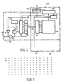
- Fig. 4 is a block diagram of a device comprising a gate connecting element.
- Block 100 comprises a transceiver device to be connected to a single wire bus symbolized by connection 80.
- a receiver amplifier 82 feeding a signal comparator 86 as well as a shift register 90 are coupled to this connection 80.
- a series output of shift register 90 is connected to transmitter amplifier 84 and also to comparator 86.
- the transmitter amplifier is also connected to the bus.
- shift register 90 In the receive position, shift register 90 is serially loaded. In the send position, shift register 90 is read in series. If, in the latter case, the comparator 86 detects a discrepancy, this implies that the transmitted signal looses an arbitration and the relevant station, in this case the gate connecting element, is to stop transmitting.
- Element 88 is a detector. It can in the first place detect the bits indicating a short-frame; if these bits are received the gate connecting element is deactivated. The bits of the priority byte are then only used for settling the arbitration between the prospective transmitter stations. If no short frame is concerned, the byte PR is stored in data RAM 96 by data register 94. In specific cases when the frame is transported, the gate connecting element generates its own individual priority byte and deactivates the received priority byte which is thus superseded. After the byte PR the byte SA is received.
- the microprocessor 106 may be a conventional building block which, however, is programmed in a special way. If the addresses in the memory 96 range from 0...255, and the number of routing addresses range from 0...7, the addresses after being transposed are read according to Table 1. The first line shows the order in which the bytes are written. The second line shows the order in which they are read if a single routing address, the ultimate destination address, is present. In that case RA1(5) is read at position 2 and DA (target address) at position 1, and source address SA(1) at position 5. If there are two routing addresses, SA is read at position 7 and so on, up to, eventually, position 11, if there are 7 routing addresses. The addresses are supplied by the controller 108 of the microprocessor 106 which is connected to the register 110.
- the microprocessor 106 comprises not more than a single bus 92 for data and addresses. In many cases there are two separate buses. For simplicity this is not further discussed: in that case there will generally be in excess of 8 address bits.
- the memory 96 can then, for example, accommodate two frames which are received simultaneously (more or less) at terminals 80, 112.
- the memory 96 can then accommodate further user information, for example, if the relevant gate connecting element forms part of a controller which transmits preset control frames to respective stations at specific instants.
- the local device may also comprise user input/output equipment 114 such as a keyboard and a screen. In this case the station function is integrated to a large extent with that of the gate connecting element.
- the user function comprises an individual transceiver device (100, 98) on one of the two bus terminals.
- an individual transceiver device 100, 98
- Different arrangements such as may be present have not been indicated separately for simplicity: - physical conversion between the signals at terminals 80,112 (I.R/twisted pair/coax) - ditto protocol conversion - separate data processing in the user's function - detailed structure of the microprocessor of the gate connecting element.
Landscapes
- Engineering & Computer Science (AREA)
- General Physics & Mathematics (AREA)
- Physics & Mathematics (AREA)
- Theoretical Computer Science (AREA)
- Computer Networks & Wireless Communication (AREA)
- Signal Processing (AREA)
- Computer Hardware Design (AREA)
- Software Systems (AREA)
- General Engineering & Computer Science (AREA)
- Small-Scale Networks (AREA)
- Devices For Checking Fares Or Tickets At Control Points (AREA)
- Mobile Radio Communication Systems (AREA)
- Radar Systems Or Details Thereof (AREA)
- Selective Calling Equipment (AREA)
Priority Applications (1)
| Application Number | Priority Date | Filing Date | Title |
|---|---|---|---|
| AT89202167T ATE103441T1 (de) | 1988-08-30 | 1989-08-28 | Kommunikationsbussystem, station zur verwendung in einem derartigen system, und gatterverbindungselement zur verwendung in einem derartigen system und geraet mit einem derartigen gatterverbindungselement. |
Applications Claiming Priority (2)
| Application Number | Priority Date | Filing Date | Title |
|---|---|---|---|
| NL8802132A NL8802132A (nl) | 1988-08-30 | 1988-08-30 | Lokaal kommunikatiebussysteem, station voor gebruik in zo een systeem, en poortverbindingselement voor gebruik in zo een systeem, en apparaat bevattende zo een poortverbindingselement. |
| NL8802132 | 1988-08-30 |
Publications (2)
| Publication Number | Publication Date |
|---|---|
| EP0357136A1 true EP0357136A1 (fr) | 1990-03-07 |
| EP0357136B1 EP0357136B1 (fr) | 1994-03-23 |
Family
ID=19852821
Family Applications (1)
| Application Number | Title | Priority Date | Filing Date |
|---|---|---|---|
| EP89202167A Expired - Lifetime EP0357136B1 (fr) | 1988-08-30 | 1989-08-28 | Système omnibus de communication, station destinée à être utilisée dans un tel système, élément de raccordement de porte destiné à être utilisé dans un tel système et dispositif comprenant un tel élément de raccordement de porte |
Country Status (9)
| Country | Link |
|---|---|
| US (1) | US5046065A (fr) |
| EP (1) | EP0357136B1 (fr) |
| JP (1) | JPH02113695A (fr) |
| KR (1) | KR0142086B1 (fr) |
| AT (1) | ATE103441T1 (fr) |
| DE (1) | DE68914065T2 (fr) |
| ES (1) | ES2051988T3 (fr) |
| FI (1) | FI96995C (fr) |
| NL (1) | NL8802132A (fr) |
Cited By (4)
| Publication number | Priority date | Publication date | Assignee | Title |
|---|---|---|---|---|
| EP0518596A1 (fr) * | 1991-06-14 | 1992-12-16 | Digital Equipment Corporation | Routeur utilisant la résolution des adresses à distance pour permettre d'envoyer des données comme par un pont |
| US5500860A (en) * | 1991-06-14 | 1996-03-19 | Digital Equipment Corporation | Router using multiple hop redirect messages to enable bridge like data forwarding |
| WO2002007123A1 (fr) * | 2000-07-17 | 2002-01-24 | Siemens Aktiengesellschaft | Procede de transmission de donnees |
| EP1912384A1 (fr) * | 2006-10-09 | 2008-04-16 | Honeywell International Inc. | Routeur de port de bus de gestion de système |
Families Citing this family (12)
| Publication number | Priority date | Publication date | Assignee | Title |
|---|---|---|---|---|
| US5481540A (en) * | 1990-08-24 | 1996-01-02 | At&T Corp. | FDDI bridge frame learning and filtering apparatus and method |
| US5313465A (en) * | 1992-05-13 | 1994-05-17 | Digital Equipment Corporation | Method of merging networks across a common backbone network |
| JP3281043B2 (ja) * | 1992-08-06 | 2002-05-13 | マツダ株式会社 | 多重伝送装置 |
| US5469432A (en) * | 1993-08-26 | 1995-11-21 | Gat; Erann | High-speed digital communications network |
| US7099472B2 (en) * | 2000-07-20 | 2006-08-29 | The Directv Group, Inc. | Method and apparatus for securing digital video recording |
| US6660948B2 (en) | 2001-02-28 | 2003-12-09 | Vip Investments Ltd. | Switch matrix |
| US7755506B1 (en) | 2003-09-03 | 2010-07-13 | Legrand Home Systems, Inc. | Automation and theater control system |
| US7394451B1 (en) | 2003-09-03 | 2008-07-01 | Vantage Controls, Inc. | Backlit display with motion sensor |
| US7307542B1 (en) | 2003-09-03 | 2007-12-11 | Vantage Controls, Inc. | System and method for commissioning addressable lighting systems |
| US7778262B2 (en) | 2005-09-07 | 2010-08-17 | Vantage Controls, Inc. | Radio frequency multiple protocol bridge |
| US11256642B2 (en) | 2019-05-14 | 2022-02-22 | Qorvo Us, Inc. | Envelope tracking amplifier apparatus incorporating single-wire peer-to-peer bus |
| AT522607B1 (de) * | 2019-05-23 | 2024-09-15 | Sticht Tech Gmbh | Verfahren zur Datenübertragung |
Citations (5)
| Publication number | Priority date | Publication date | Assignee | Title |
|---|---|---|---|---|
| US3731002A (en) * | 1970-10-08 | 1973-05-01 | Bell Telephone Labor Inc | Interconnected loop data block transmission system |
| EP0060535A2 (fr) * | 1981-03-12 | 1982-09-22 | Recognition Equipment Incorporated | Réseau de multitraitement de données |
| EP0156542A2 (fr) * | 1984-03-19 | 1985-10-02 | International Computers Limited | Interconnexion de réseaux de communications |
| DE3514334A1 (de) * | 1985-04-19 | 1986-10-23 | Siemens AG, 1000 Berlin und 8000 München | Gebaeude-steuersystem |
| WO1987006379A1 (fr) * | 1986-04-09 | 1987-10-22 | Regulex Ges. F. Technische Informationssysteme Zen | Procede et dispositif de transmission de donnees |
Family Cites Families (9)
| Publication number | Priority date | Publication date | Assignee | Title |
|---|---|---|---|---|
| NL191374C (nl) * | 1980-04-23 | 1995-06-16 | Philips Nv | Communicatiesysteem met een communicatiebus. |
| US4331834A (en) * | 1980-10-29 | 1982-05-25 | Siemens Corporation | Modular telecommunication system |
| US4706080A (en) * | 1985-08-26 | 1987-11-10 | Bell Communications Research, Inc. | Interconnection of broadcast networks |
| JPS6422230A (en) * | 1987-07-17 | 1989-01-25 | Matsushita Electric Industrial Co Ltd | Electric cleaner |
| JPS6478052A (en) * | 1987-09-19 | 1989-03-23 | Fujitsu Ltd | Method and device for relaying local area network |
| US4811337A (en) * | 1988-01-15 | 1989-03-07 | Vitalink Communications Corporation | Distributed load sharing |
| EP0349099B1 (fr) * | 1988-06-27 | 1995-03-01 | Digital Equipment Corporation | Partage de charge transparent pour réseaux parallèles |
| US4947390A (en) * | 1989-03-22 | 1990-08-07 | Hewlett-Packard Company | Method for data transfer through a bridge to a network requiring source route information |
| US4933938A (en) * | 1989-03-22 | 1990-06-12 | Hewlett-Packard Company | Group address translation through a network bridge |
-
1988
- 1988-08-30 NL NL8802132A patent/NL8802132A/nl not_active Application Discontinuation
-
1989
- 1989-08-24 US US07/398,111 patent/US5046065A/en not_active Expired - Fee Related
- 1989-08-25 FI FI894008A patent/FI96995C/fi not_active IP Right Cessation
- 1989-08-28 KR KR1019890012232A patent/KR0142086B1/ko not_active Expired - Fee Related
- 1989-08-28 AT AT89202167T patent/ATE103441T1/de not_active IP Right Cessation
- 1989-08-28 ES ES89202167T patent/ES2051988T3/es not_active Expired - Lifetime
- 1989-08-28 EP EP89202167A patent/EP0357136B1/fr not_active Expired - Lifetime
- 1989-08-28 DE DE68914065T patent/DE68914065T2/de not_active Expired - Fee Related
- 1989-08-28 JP JP1221372A patent/JPH02113695A/ja active Pending
Patent Citations (5)
| Publication number | Priority date | Publication date | Assignee | Title |
|---|---|---|---|---|
| US3731002A (en) * | 1970-10-08 | 1973-05-01 | Bell Telephone Labor Inc | Interconnected loop data block transmission system |
| EP0060535A2 (fr) * | 1981-03-12 | 1982-09-22 | Recognition Equipment Incorporated | Réseau de multitraitement de données |
| EP0156542A2 (fr) * | 1984-03-19 | 1985-10-02 | International Computers Limited | Interconnexion de réseaux de communications |
| DE3514334A1 (de) * | 1985-04-19 | 1986-10-23 | Siemens AG, 1000 Berlin und 8000 München | Gebaeude-steuersystem |
| WO1987006379A1 (fr) * | 1986-04-09 | 1987-10-22 | Regulex Ges. F. Technische Informationssysteme Zen | Procede et dispositif de transmission de donnees |
Non-Patent Citations (1)
| Title |
|---|
| IBM TECHNICAL DISCLOSURE BULLETIN, vol. 26, no. 3A, August 1983, pages 1198-1200, New York, US; R.C. DIXON: "Group address structure for network service nodes" * |
Cited By (6)
| Publication number | Priority date | Publication date | Assignee | Title |
|---|---|---|---|---|
| EP0518596A1 (fr) * | 1991-06-14 | 1992-12-16 | Digital Equipment Corporation | Routeur utilisant la résolution des adresses à distance pour permettre d'envoyer des données comme par un pont |
| US5420862A (en) * | 1991-06-14 | 1995-05-30 | Digital Equipment Corporation | Router using remote address resolution to enable bridge like data forwarding |
| US5500860A (en) * | 1991-06-14 | 1996-03-19 | Digital Equipment Corporation | Router using multiple hop redirect messages to enable bridge like data forwarding |
| US5796740A (en) * | 1991-06-14 | 1998-08-18 | Cabletron Systems, Inc. | Router using multiple hop redirect messages to enable bridge like data forwarding |
| WO2002007123A1 (fr) * | 2000-07-17 | 2002-01-24 | Siemens Aktiengesellschaft | Procede de transmission de donnees |
| EP1912384A1 (fr) * | 2006-10-09 | 2008-04-16 | Honeywell International Inc. | Routeur de port de bus de gestion de système |
Also Published As
| Publication number | Publication date |
|---|---|
| KR900003756A (ko) | 1990-03-27 |
| JPH02113695A (ja) | 1990-04-25 |
| US5046065A (en) | 1991-09-03 |
| EP0357136B1 (fr) | 1994-03-23 |
| FI96995B (fi) | 1996-06-14 |
| DE68914065T2 (de) | 1994-09-29 |
| KR0142086B1 (ko) | 1998-07-01 |
| NL8802132A (nl) | 1990-03-16 |
| FI894008A7 (fi) | 1990-03-01 |
| ES2051988T3 (es) | 1994-07-01 |
| DE68914065D1 (de) | 1994-04-28 |
| FI96995C (fi) | 1996-09-25 |
| FI894008A0 (fi) | 1989-08-25 |
| ATE103441T1 (de) | 1994-04-15 |
Similar Documents
| Publication | Publication Date | Title |
|---|---|---|
| US5046065A (en) | Communication system, a station to be used in such a system, and a gate connecting element to be used in such a system, as well as a device comprising such a gate connecting element | |
| US4689785A (en) | Data transmission system | |
| US4337465A (en) | Line driver circuit for a local area contention network | |
| US4200936A (en) | Asynchronous bidirectional direct serial interface linking a programmable machine function controller and a numerical control | |
| EP0544964B1 (fr) | Appareil à mémorisation et à transmission et méthode pour maintenir l'intégrité des données pendant leur stockage | |
| US5570085A (en) | Programmable distributed appliance control system | |
| US5003533A (en) | Node processing system | |
| EP0076880A1 (fr) | Réseau local à contention pour système de communication de données | |
| EP0507381B1 (fr) | Procédé de traitement d'ordres de commande | |
| US4642630A (en) | Method and apparatus for bus contention resolution | |
| GB2121222A (en) | Interruption handling in data transmission system | |
| JP2685078B2 (ja) | 多ステーション通信バスシステム及びステーション | |
| NL8702394A (nl) | Interface voor een verbindingsnetwerk tussen afzonderlijke stations enerzijds en een voor het berichtenverkeer tussen deze stations gebruikt fysiek medium anderzijds. | |
| US6907488B1 (en) | Serial data transmission via a bus system | |
| US5353284A (en) | Data transmission system | |
| JPH08503353A (ja) | 通信バスシステムとかかるシステムで使用されるステーション | |
| US4623885A (en) | Method and arrangement for distribution of send permission to terminals in a telecommunication network | |
| US5249182A (en) | Communication bus system with lock/unlock capability | |
| FI90483B (fi) | Tiedonsiirtomenetelmä häiriöllisessä ympäristössä toimivaa toimilaitejärjestelmää varten | |
| JP2558062B2 (ja) | システム・バスを介して他のアダプタに可変サイズのデータ・ブロックを転送するためのアダプタ | |
| US5535344A (en) | Device for the connection of an apparatus to a transmission channel | |
| HU205511B (en) | Method for processing data packets in the information systems | |
| JPS5848593A (ja) | ボ−リング伝送方式 | |
| JPS61270952A (ja) | デ−タ伝送方式 | |
| JP2696105B2 (ja) | ネットワーク相互接続回路 |
Legal Events
| Date | Code | Title | Description |
|---|---|---|---|
| PUAI | Public reference made under article 153(3) epc to a published international application that has entered the european phase |
Free format text: ORIGINAL CODE: 0009012 |
|
| AK | Designated contracting states |
Kind code of ref document: A1 Designated state(s): AT BE CH DE ES FR GB IT LI NL SE |
|
| 17P | Request for examination filed |
Effective date: 19900904 |
|
| 17Q | First examination report despatched |
Effective date: 19920722 |
|
| GRAA | (expected) grant |
Free format text: ORIGINAL CODE: 0009210 |
|
| AK | Designated contracting states |
Kind code of ref document: B1 Designated state(s): AT BE CH DE ES FR GB IT LI NL SE |
|
| PG25 | Lapsed in a contracting state [announced via postgrant information from national office to epo] |
Ref country code: SE Free format text: THE PATENT HAS BEEN ANNULLED BY A DECISION OF A NATIONAL AUTHORITY Effective date: 19940323 Ref country code: NL Effective date: 19940323 Ref country code: LI Effective date: 19940323 Ref country code: CH Effective date: 19940323 Ref country code: BE Effective date: 19940323 |
|
| REF | Corresponds to: |
Ref document number: 103441 Country of ref document: AT Date of ref document: 19940415 Kind code of ref document: T |
|
| REF | Corresponds to: |
Ref document number: 68914065 Country of ref document: DE Date of ref document: 19940428 |
|
| ITF | It: translation for a ep patent filed | ||
| ET | Fr: translation filed | ||
| REG | Reference to a national code |
Ref country code: CH Ref legal event code: PL |
|
| NLV1 | Nl: lapsed or annulled due to failure to fulfill the requirements of art. 29p and 29m of the patents act | ||
| PLBE | No opposition filed within time limit |
Free format text: ORIGINAL CODE: 0009261 |
|
| STAA | Information on the status of an ep patent application or granted ep patent |
Free format text: STATUS: NO OPPOSITION FILED WITHIN TIME LIMIT |
|
| 26N | No opposition filed | ||
| ITPR | It: changes in ownership of a european patent |
Owner name: CAMBIO RAGIONE SOCIALE;PHILIPS ELECTRONICS N.V. |
|
| REG | Reference to a national code |
Ref country code: FR Ref legal event code: CD |
|
| REG | Reference to a national code |
Ref country code: ES Ref legal event code: PC2A Owner name: PHILIPS ELECTRONICS N.V. |
|
| PGFP | Annual fee paid to national office [announced via postgrant information from national office to epo] |
Ref country code: GB Payment date: 19980804 Year of fee payment: 10 |
|
| PGFP | Annual fee paid to national office [announced via postgrant information from national office to epo] |
Ref country code: ES Payment date: 19980817 Year of fee payment: 10 |
|
| PGFP | Annual fee paid to national office [announced via postgrant information from national office to epo] |
Ref country code: FR Payment date: 19980818 Year of fee payment: 10 |
|
| PGFP | Annual fee paid to national office [announced via postgrant information from national office to epo] |
Ref country code: AT Payment date: 19980827 Year of fee payment: 10 |
|
| REG | Reference to a national code |
Ref country code: FR Ref legal event code: CD |
|
| PGFP | Annual fee paid to national office [announced via postgrant information from national office to epo] |
Ref country code: DE Payment date: 19981022 Year of fee payment: 10 |
|
| REG | Reference to a national code |
Ref country code: ES Ref legal event code: PC2A |
|
| PG25 | Lapsed in a contracting state [announced via postgrant information from national office to epo] |
Ref country code: GB Free format text: LAPSE BECAUSE OF NON-PAYMENT OF DUE FEES Effective date: 19990828 Ref country code: AT Free format text: LAPSE BECAUSE OF NON-PAYMENT OF DUE FEES Effective date: 19990828 |
|
| PG25 | Lapsed in a contracting state [announced via postgrant information from national office to epo] |
Ref country code: ES Free format text: LAPSE BECAUSE OF NON-PAYMENT OF DUE FEES Effective date: 19990829 |
|
| GBPC | Gb: european patent ceased through non-payment of renewal fee |
Effective date: 19990828 |
|
| PG25 | Lapsed in a contracting state [announced via postgrant information from national office to epo] |
Ref country code: FR Free format text: LAPSE BECAUSE OF NON-PAYMENT OF DUE FEES Effective date: 20000428 |
|
| PG25 | Lapsed in a contracting state [announced via postgrant information from national office to epo] |
Ref country code: DE Free format text: LAPSE BECAUSE OF NON-PAYMENT OF DUE FEES Effective date: 20000601 |
|
| REG | Reference to a national code |
Ref country code: FR Ref legal event code: ST |
|
| REG | Reference to a national code |
Ref country code: ES Ref legal event code: FD2A Effective date: 20000911 |
|
| PG25 | Lapsed in a contracting state [announced via postgrant information from national office to epo] |
Ref country code: IT Free format text: LAPSE BECAUSE OF NON-PAYMENT OF DUE FEES;WARNING: LAPSES OF ITALIAN PATENTS WITH EFFECTIVE DATE BEFORE 2007 MAY HAVE OCCURRED AT ANY TIME BEFORE 2007. THE CORRECT EFFECTIVE DATE MAY BE DIFFERENT FROM THE ONE RECORDED. Effective date: 20050828 |