EP0357153A1 - Dispositif mobile pour pulvériser les plantes dans les champs - Google Patents
Dispositif mobile pour pulvériser les plantes dans les champs Download PDFInfo
- Publication number
- EP0357153A1 EP0357153A1 EP89202216A EP89202216A EP0357153A1 EP 0357153 A1 EP0357153 A1 EP 0357153A1 EP 89202216 A EP89202216 A EP 89202216A EP 89202216 A EP89202216 A EP 89202216A EP 0357153 A1 EP0357153 A1 EP 0357153A1
- Authority
- EP
- European Patent Office
- Prior art keywords
- casing
- air
- plants
- fan
- spray
- Prior art date
- Legal status (The legal status is an assumption and is not a legal conclusion. Google has not performed a legal analysis and makes no representation as to the accuracy of the status listed.)
- Granted
Links
- 238000005507 spraying Methods 0.000 title claims abstract description 21
- 239000007921 spray Substances 0.000 claims abstract description 46
- 239000007788 liquid Substances 0.000 claims description 10
- 239000000284 extract Substances 0.000 claims description 5
- 238000000605 extraction Methods 0.000 claims description 4
- 238000007664 blowing Methods 0.000 abstract description 2
- 239000003570 air Substances 0.000 description 27
- 241000196324 Embryophyta Species 0.000 description 15
- 239000012080 ambient air Substances 0.000 description 1
- 239000000463 material Substances 0.000 description 1
- 238000000034 method Methods 0.000 description 1
- 230000002441 reversible effect Effects 0.000 description 1
Images

Classifications
-
- A—HUMAN NECESSITIES
- A01—AGRICULTURE; FORESTRY; ANIMAL HUSBANDRY; HUNTING; TRAPPING; FISHING
- A01M—CATCHING, TRAPPING OR SCARING OF ANIMALS; APPARATUS FOR THE DESTRUCTION OF NOXIOUS ANIMALS OR NOXIOUS PLANTS
- A01M7/00—Special adaptations or arrangements of liquid-spraying apparatus for purposes covered by this subclass
- A01M7/005—Special arrangements or adaptations of the spraying or distributing parts, e.g. adaptations or mounting of the spray booms, mounting of the nozzles, protection shields
- A01M7/0064—Protection shields
- A01M7/0067—Protection shields with recovering of liquids
-
- A—HUMAN NECESSITIES
- A01—AGRICULTURE; FORESTRY; ANIMAL HUSBANDRY; HUNTING; TRAPPING; FISHING
- A01M—CATCHING, TRAPPING OR SCARING OF ANIMALS; APPARATUS FOR THE DESTRUCTION OF NOXIOUS ANIMALS OR NOXIOUS PLANTS
- A01M7/00—Special adaptations or arrangements of liquid-spraying apparatus for purposes covered by this subclass
-
- A—HUMAN NECESSITIES
- A01—AGRICULTURE; FORESTRY; ANIMAL HUSBANDRY; HUNTING; TRAPPING; FISHING
- A01M—CATCHING, TRAPPING OR SCARING OF ANIMALS; APPARATUS FOR THE DESTRUCTION OF NOXIOUS ANIMALS OR NOXIOUS PLANTS
- A01M7/00—Special adaptations or arrangements of liquid-spraying apparatus for purposes covered by this subclass
- A01M7/0003—Atomisers or mist blowers
- A01M7/0014—Field atomisers, e.g. orchard atomisers, self-propelled, drawn or tractor-mounted
Definitions
- the invention relates to a mobile device for spraying plants in the field.
- the object of the invention is to produce such a device which combines optimum utilization of spray product with the minimum of harm to the environment and nuisance to operating persons in the area.
- such a device has, on a carrier device which can be moved through between rows of plants or along a strip of plants, a tent-shaped casing which covers the plants to be sprayed and substantially shuts off the space inside said casing from the environment, said carrier device bearing a fan, connecting to a pipe system to extract air from the casing and blow it back into the casing near the spray means.
- the fan extract is advisable to make from approximately the longitudinal centre of the casing. This is also most often advantageous if the device has two opposite directions of travel while spraying. For the spraying of trees in particular it may be useful to fit the spray nozzles practically in a single transverse plane at right angles to the direction of forward movement, as known per se, and the fan can then advantageously lie centred above them.
- the invention also relates to a further development of the above-mentioned features, as yet to be described.
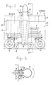
- the device according to Figs. 1 - 3 has a rigid gantry structure 1 with upright legs 2 and 3 and a horizontal top leg 4. On horizontal arms 5 on leg 2 this gantry structure carries swivelling and drivable wheels 6 and 7, a stock tank 8 for spray product, and a drive unit 9 for said wheels.
- Leg 3 bears two non-driven and freely swivellable piano wheels 10 at the bottom.
- a tent-shaped casing 11 which can have a bar-type or tubular frame (not shown) over which, for example, canvas is stretched, is suspended in this gantry.
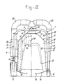
- the casing 11 has a flat top wall 12 in the centre, merging towards both sides into downward-sloping parts 13, which in turn merge into more steeply downward-sloping side wall parts 14, at the bottom along the entire bottom edge merging into flat parts 15 sloping slightly towards the centre, and each ending in a channel 16.
- This shape is such that the trees 17 of a row of trees to be sprayed are well enclosed.
- the frame of the casing is made flexible, for example through rubber parts therein, in order to permit the wheels to swivel and to press the casing temporarily inwards in the process.
- the side wall parts 14 at those wheels may also extend more vertically, in order to leave more space between them and the wheels 6 and 7 and their bearing elements.
- flaps for example of rubber or canvas, which serve to keep in the air inside the casing and allow as little air as possible in from the outside.
- flaps can be in different forms. Shown on the right in Fig. 2 is a flap 18 which just allows the trees 17 through without touching. Shown on the left in Fig. 2 is a flap 19 which leaves more space between casing and tree, but is touched at the bottom by the trees and pressed away as it passes. Individual strip-type flaps can also hang next to each other in the casing and do touch the trees (flaps 20) or just miss them (flaps 21). The flaps 20 touching the trees can also be longer. The flaps may be easily removable to replace them by other flaps depending on the shape of the trees or the stage of development of foliage of the same trees.
- Fig. 1 vertical dashed lines indicate how these flaps can be placed one after the other in the lengthwise direction of the device, of course apart from flaps which are disposed in the end faces 22 of the casing.
- flaps are disposed at equal intervals, viewed in the direction of travel of the device, but only on either side of the gantry legs 2 and 3, and thus not in the centre lengthwise, where spray means yet to be described are fitted. It is preferable for flaps in and closer to said end faces 22 to seal off the transverse space in the casing 11 more than flaps lying more towards the centre of the casing.
- said end faces 22 long individual strip-type flaps next to each other and touching the trees are particularly suitable.
- FIG. 3 shows how said slit can be fairly wide, with a screen 27 in the centre thereof, in the shadow of which lies a pipe 24 for liquid spray product, on which a number of spray nozzles 29 are fitted.
- the air delivery slit is thus divided into two fairly narrow slits 30 along each side of the screen 27, which can each be narrowed or completely closed with a slide 31 through direct or remote control, and manually or mechanically.
- the flows of air directly along the liquid jets out of the spray nozzles 29 help the liquid in said jets to remain directed well onto the trees.
- the pipes 26 are swivellable about their vertical axes in both directions through a limited angle, say 40°, for example through a motor engaging with a pinion 32, which meshes with a gear ring 33 along part of the periphery of each pipe 26.
- a limited angle say 40°
- the casing is locally flexible enough in the walls 14, it can connect directly to the outside walls of the slits 30, as shown in Fig. 3, in which case so much space, for example through folds or corrugations, as shown, in the canvas or the like of the wall parts 14 is present that it can follow said swivelling.
- the casing 11 When the device is travelling with the legs 2 and 3 of the gantry through between rows of trees the casing 11 encloses in succession the trees in a row to be sprayed, and the trees are sprayed when they are completely inside the casing. It was found that it is better not to spray the trees with jets essentially at right angles to the direction of forward movement of the device, but with jets which are directed at an angle relative to said direction. This was done until now by directing the spray nozzles 29 backwards relative to the direction of travel. It has now been found that trees can be sprayed more efficiently - i.e. with fuller use of the spray liquid, thus with lower consumption thereof - if spraying takes place in the forward direction.
- the device can travel in two opposite directions over the trees, this means that it must be possible to swivel the spray nozzles 29 relative to the position of Fig. 3 in both directions through the same angle. In addition, a finer adjustment of said swivel angle is, of course, possible.
- the flat bottom parts 15 of the casing serve to collect a large part of the spray liquid which has not touched the trees, or drips quickly off them, and to convey it to the channels 16, from where this liquid can be conveyed back through pipes and by pump or other pressure difference means (not shown) into the spraying system, e.g. into stock tank 8.
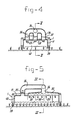
- FIGs. 4 and 5 show schematically a device according to the invention for spraying low crops, it being assumed that it is sufficient to spray these only from the top.
- the casing can have a closed front and rear wall 40, according to Fig. 4 with a bottom edge which just allows through the plants (or just touches them without damaging them).
- the pipe 34 here splits up into three pipes 36, each leading to an air chamber 37, which extends in the lengthwise direction over the spray nozzles 29 above one row of plants, and connects to apertures in the top wall of the casing, in order thus to blow the air drawn in by fan 35 downwards along the spray nozzles underneath. All apertures in the casing for allowing through air can have grilles and/or slides or the like for varying their air passage surface.
- transverse flaps 38 which here can have over the entire width of the casing a horizontal bottom edge which, for example for flaps further from the extraction aperture of fan 35, lies lower than for flaps closer to it, in order to obtain a uniform air flow through underneath to the fan (Fig. 5).
- Fig. 6 shows another embodiment of the device according to the invention, where there is also quite a distance in the direction of travel between the zone of extracting air from the casing and the zone of blowing thereof into the casing, particularly suited for trees, shrubs and higher plants.
- the air is sucked from the interior of the casing, of which the vertical side walls 14 are shown, through a substantially vertical slot 41 at one end by a fan 42, which in this case is embodied as a cross-flow fan with a vertical rotor, through which the air passes crosswise, in this case from left to right, by the rotation of the rotor, provided with suitable blades, as is known as such.
- Ducts 43 and 44 guide the air to and from the fan respectively.
- the ducts 44 guide the air to blow-in slots 45 and in these slots are spray means 46 of a type as given in Fig. 3.
- spray means 47 just to the side of the slots 45, instead of or supplementary to the spray means 46.
- the casing has lower walls 15 extending towards the trunks of the trees as in Fig. 2.
- This device may be moved to the right in Fig. 6 or to the left, the latter possibility giving a better result, as stated in principle above.
- the slots 41 would also have spray means like 46 and/or 47, and if the fans are reversible, the device may be moved in any direction during spraying, there being switching means for operating only the spray means at the blow-out slots.
- flaps as described above may be omitted altogether, the air flow from and into the slots 41 and 45 acting as curtains to shroud the inside of the casing sufficiently from the ambient air.
- the fans 42 long rotors or to embody them with two or more coaxial rotors, so that the ducts 43 and 44 can be rectangular in side view with substantially horizontal top and bottom walls.
- a device to the invention may have a casing with the means shown on one side of the rows of trees in Fig. 6, but turned over 90° to make one of the casing walls 14 of Fig. 6 to form the roof of the casing.
- the breadth of the device is selected in such a way that the wheels run in the furrows between ridges, while the device can, of course, also travel with the wheels over the crop where there is a full field crop.
Landscapes
- Life Sciences & Earth Sciences (AREA)
- Engineering & Computer Science (AREA)
- Insects & Arthropods (AREA)
- Pest Control & Pesticides (AREA)
- Wood Science & Technology (AREA)
- Zoology (AREA)
- Environmental Sciences (AREA)
- Catching Or Destruction (AREA)
- Special Spraying Apparatus (AREA)
- Fertilizing (AREA)
- Cultivation Receptacles Or Flower-Pots, Or Pots For Seedlings (AREA)
Priority Applications (1)
| Application Number | Priority Date | Filing Date | Title |
|---|---|---|---|
| AT89202216T ATE71485T1 (de) | 1988-09-01 | 1989-08-31 | Bewegliche vorrichtung zum bespruehen von pflanzen auf dem feld. |
Applications Claiming Priority (2)
| Application Number | Priority Date | Filing Date | Title |
|---|---|---|---|
| NL8802164A NL8802164A (nl) | 1988-09-01 | 1988-09-01 | Verrijdbare inrichting voor het bespuiten van planten op het veld. |
| NL8802164 | 1988-09-01 |
Publications (2)
| Publication Number | Publication Date |
|---|---|
| EP0357153A1 true EP0357153A1 (fr) | 1990-03-07 |
| EP0357153B1 EP0357153B1 (fr) | 1992-01-15 |
Family
ID=19852842
Family Applications (1)
| Application Number | Title | Priority Date | Filing Date |
|---|---|---|---|
| EP89202216A Expired - Lifetime EP0357153B1 (fr) | 1988-09-01 | 1989-08-31 | Dispositif mobile pour pulvériser les plantes dans les champs |
Country Status (6)
| Country | Link |
|---|---|
| EP (1) | EP0357153B1 (fr) |
| AT (1) | ATE71485T1 (fr) |
| DE (1) | DE68900715D1 (fr) |
| ES (1) | ES2030263T3 (fr) |
| GR (1) | GR3004013T3 (fr) |
| NL (1) | NL8802164A (fr) |
Cited By (3)
| Publication number | Priority date | Publication date | Assignee | Title |
|---|---|---|---|---|
| EP0549058A1 (fr) * | 1991-12-20 | 1993-06-30 | Mathijs René Marie Jozef Van den Munckhof | Pulverisateur tubulaire |
| WO2010000896A1 (fr) * | 2008-07-01 | 2010-01-07 | Juan Sentis Ortilles | Dispositif de pulvérisation de plantes |
| EP3210467A1 (fr) * | 2016-02-23 | 2017-08-30 | Yanmar Co., Ltd. | Vehicule de travail |
Citations (5)
| Publication number | Priority date | Publication date | Assignee | Title |
|---|---|---|---|---|
| FR2501461A1 (fr) * | 1981-03-13 | 1982-09-17 | Mem Mueszaki Intezet | Machine de pulverisation agricole |
| DE3316110A1 (de) * | 1983-05-03 | 1984-11-08 | Hans Wanner GmbH, Maschinenbau, 7988 Wangen | Spruehgeraet fuer raumkulturen in der landwirtschaft |
| DE8416938U1 (de) * | 1984-06-02 | 1985-09-26 | Oberhofer, Alfred, 6731 Kirrweiler | Fahrbares Spritzgerät |
| GB2157935A (en) * | 1984-04-27 | 1985-11-06 | Ramon Barry Rogers | Field sprayer and enclosure member therefore |
| FR2606672A1 (fr) * | 1986-11-13 | 1988-05-20 | Bourgeois Gerard | Dispositif pour pulveriser des liquides fertilisants, insecticides ou autres sur des arbres |
-
1988
- 1988-09-01 NL NL8802164A patent/NL8802164A/nl not_active Application Discontinuation
-
1989
- 1989-08-31 DE DE8989202216T patent/DE68900715D1/de not_active Revoked
- 1989-08-31 AT AT89202216T patent/ATE71485T1/de not_active IP Right Cessation
- 1989-08-31 EP EP89202216A patent/EP0357153B1/fr not_active Expired - Lifetime
- 1989-08-31 ES ES198989202216T patent/ES2030263T3/es not_active Expired - Lifetime
-
1992
- 1992-03-11 GR GR920400402T patent/GR3004013T3/el unknown
Patent Citations (5)
| Publication number | Priority date | Publication date | Assignee | Title |
|---|---|---|---|---|
| FR2501461A1 (fr) * | 1981-03-13 | 1982-09-17 | Mem Mueszaki Intezet | Machine de pulverisation agricole |
| DE3316110A1 (de) * | 1983-05-03 | 1984-11-08 | Hans Wanner GmbH, Maschinenbau, 7988 Wangen | Spruehgeraet fuer raumkulturen in der landwirtschaft |
| GB2157935A (en) * | 1984-04-27 | 1985-11-06 | Ramon Barry Rogers | Field sprayer and enclosure member therefore |
| DE8416938U1 (de) * | 1984-06-02 | 1985-09-26 | Oberhofer, Alfred, 6731 Kirrweiler | Fahrbares Spritzgerät |
| FR2606672A1 (fr) * | 1986-11-13 | 1988-05-20 | Bourgeois Gerard | Dispositif pour pulveriser des liquides fertilisants, insecticides ou autres sur des arbres |
Cited By (3)
| Publication number | Priority date | Publication date | Assignee | Title |
|---|---|---|---|---|
| EP0549058A1 (fr) * | 1991-12-20 | 1993-06-30 | Mathijs René Marie Jozef Van den Munckhof | Pulverisateur tubulaire |
| WO2010000896A1 (fr) * | 2008-07-01 | 2010-01-07 | Juan Sentis Ortilles | Dispositif de pulvérisation de plantes |
| EP3210467A1 (fr) * | 2016-02-23 | 2017-08-30 | Yanmar Co., Ltd. | Vehicule de travail |
Also Published As
| Publication number | Publication date |
|---|---|
| ES2030263T3 (es) | 1992-10-16 |
| DE68900715D1 (de) | 1992-02-27 |
| NL8802164A (nl) | 1990-04-02 |
| GR3004013T3 (fr) | 1993-03-31 |
| ATE71485T1 (de) | 1992-02-15 |
| EP0357153B1 (fr) | 1992-01-15 |
Similar Documents
| Publication | Publication Date | Title |
|---|---|---|
| US6302332B1 (en) | Method and apparatus for spraying trees, plants, etc | |
| US5028002A (en) | Cross-flow spray assembly | |
| US5107566A (en) | Directed discharge blower chute and method | |
| US5251818A (en) | Spraying equipment for plants grown in rows | |
| US5002227A (en) | Plant protection discharge apparatus | |
| US4433532A (en) | Lawn mower bagging system including air assist | |
| JPS6448912A (en) | Refuse cart | |
| US2220082A (en) | Spraying and dusting machine | |
| US11882822B2 (en) | System and method for spraying a product, in particular a plant-protection product | |
| EP0357153B1 (fr) | Dispositif mobile pour pulvériser les plantes dans les champs | |
| EP1449433B1 (fr) | Pulvérisateur en tunnel pour les lignes de verger, de vignoble, ou d'autres plantes | |
| GB2237823A (en) | Apparatus and method for removing fibre flocks from fibre bales | |
| EP0549058A1 (fr) | Pulverisateur tubulaire | |
| US4083773A (en) | Fruit harvesting machine with leaf separation means | |
| US4200036A (en) | Ventilation system for automated mining machines | |
| US5768743A (en) | Debris collecting apparatus | |
| US12604880B2 (en) | Bug-removal vacuum machine | |
| CN100366139C (zh) | 棉花收获机行装置的输送结构 | |
| JP3996934B2 (ja) | 茶葉摘採機 | |
| JP3886841B2 (ja) | 茶園防除機 | |
| US5094064A (en) | Duct system for a cotton harvester | |
| US2293517A (en) | Apparatus for dusting plants | |
| GB9006624D0 (en) | Waste collection | |
| AU654719B2 (en) | Spraying equipment for plants grown in rows | |
| RU2048771C1 (ru) | Аппарат для сбора легких предметов с растений |
Legal Events
| Date | Code | Title | Description |
|---|---|---|---|
| PUAI | Public reference made under article 153(3) epc to a published international application that has entered the european phase |
Free format text: ORIGINAL CODE: 0009012 |
|
| AK | Designated contracting states |
Kind code of ref document: A1 Designated state(s): AT BE CH DE ES FR GB GR IT LI LU NL SE |
|
| 17P | Request for examination filed |
Effective date: 19900817 |
|
| 17Q | First examination report despatched |
Effective date: 19910318 |
|
| GRAA | (expected) grant |
Free format text: ORIGINAL CODE: 0009210 |
|
| AK | Designated contracting states |
Kind code of ref document: B1 Designated state(s): AT BE CH DE ES FR GB GR IT LI LU NL SE |
|
| REF | Corresponds to: |
Ref document number: 71485 Country of ref document: AT Date of ref document: 19920215 Kind code of ref document: T |
|
| REF | Corresponds to: |
Ref document number: 68900715 Country of ref document: DE Date of ref document: 19920227 |
|
| ET | Fr: translation filed | ||
| ITF | It: translation for a ep patent filed | ||
| PGFP | Annual fee paid to national office [announced via postgrant information from national office to epo] |
Ref country code: GR Payment date: 19920618 Year of fee payment: 4 |
|
| PGFP | Annual fee paid to national office [announced via postgrant information from national office to epo] |
Ref country code: FR Payment date: 19920807 Year of fee payment: 4 |
|
| PGFP | Annual fee paid to national office [announced via postgrant information from national office to epo] |
Ref country code: AT Payment date: 19920813 Year of fee payment: 4 |
|
| PGFP | Annual fee paid to national office [announced via postgrant information from national office to epo] |
Ref country code: SE Payment date: 19920817 Year of fee payment: 4 |
|
| PGFP | Annual fee paid to national office [announced via postgrant information from national office to epo] |
Ref country code: DE Payment date: 19920824 Year of fee payment: 4 |
|
| PGFP | Annual fee paid to national office [announced via postgrant information from national office to epo] |
Ref country code: CH Payment date: 19920826 Year of fee payment: 4 |
|
| PGFP | Annual fee paid to national office [announced via postgrant information from national office to epo] |
Ref country code: NL Payment date: 19920831 Year of fee payment: 4 Ref country code: ES Payment date: 19920831 Year of fee payment: 4 |
|
| PGFP | Annual fee paid to national office [announced via postgrant information from national office to epo] |
Ref country code: LU Payment date: 19920903 Year of fee payment: 4 |
|
| PGFP | Annual fee paid to national office [announced via postgrant information from national office to epo] |
Ref country code: BE Payment date: 19920930 Year of fee payment: 4 |
|
| REG | Reference to a national code |
Ref country code: ES Ref legal event code: FG2A Ref document number: 2030263 Country of ref document: ES Kind code of ref document: T3 |
|
| PLBI | Opposition filed |
Free format text: ORIGINAL CODE: 0009260 |
|
| PLAB | Opposition data, opponent's data or that of the opponent's representative modified |
Free format text: ORIGINAL CODE: 0009299OPPO |
|
| 26 | Opposition filed |
Opponent name: FIRMA JOHN TECHNIK IN METALL GMBH & CO. KG Effective date: 19921015 |
|
| EPTA | Lu: last paid annual fee | ||
| R26 | Opposition filed (corrected) |
Opponent name: FIRMA JOHN TECHNIK IN METALL GMBH & CO. KG Effective date: 19921014 |
|
| NLR1 | Nl: opposition has been filed with the epo |
Opponent name: FIRMA JOHN TECHNIK IN METALL GMBH & CO.KG |
|
| NLXE | Nl: other communications concerning ep-patents (part 3 heading xe) |
Free format text: PAT.BUL.04/93 CORR.:921014 |
|
| RDAG | Patent revoked |
Free format text: ORIGINAL CODE: 0009271 |
|
| STAA | Information on the status of an ep patent application or granted ep patent |
Free format text: STATUS: PATENT REVOKED |
|
| 27W | Patent revoked |
Effective date: 19930724 |
|
| GBPR | Gb: patent revoked under art. 102 of the ep convention designating the uk as contracting state |
Free format text: 930724 |
|
| REG | Reference to a national code |
Ref country code: CH Ref legal event code: PL |
|
| NLR2 | Nl: decision of opposition | ||
| REG | Reference to a national code |
Ref country code: GR Ref legal event code: MF4A Free format text: 3004013 |
|
| EUG | Se: european patent has lapsed |
Ref document number: 89202216.1 Effective date: 19931208 |