EP0357209A1 - Deckel für Müllbehälter - Google Patents
Deckel für Müllbehälter Download PDFInfo
- Publication number
- EP0357209A1 EP0357209A1 EP89307412A EP89307412A EP0357209A1 EP 0357209 A1 EP0357209 A1 EP 0357209A1 EP 89307412 A EP89307412 A EP 89307412A EP 89307412 A EP89307412 A EP 89307412A EP 0357209 A1 EP0357209 A1 EP 0357209A1
- Authority
- EP
- European Patent Office
- Prior art keywords
- bin
- lid
- closure means
- movable lid
- frame
- Prior art date
- Legal status (The legal status is an assumption and is not a legal conclusion. Google has not performed a legal analysis and makes no representation as to the accuracy of the status listed.)
- Withdrawn
Links
- 239000002699 waste material Substances 0.000 title claims abstract description 15
- 239000002440 industrial waste Substances 0.000 abstract description 11
- 238000007789 sealing Methods 0.000 description 10
- 230000002093 peripheral effect Effects 0.000 description 3
- XEEYBQQBJWHFJM-UHFFFAOYSA-N Iron Chemical compound [Fe] XEEYBQQBJWHFJM-UHFFFAOYSA-N 0.000 description 2
- 230000005484 gravity Effects 0.000 description 2
- 241000255925 Diptera Species 0.000 description 1
- 229910000831 Steel Inorganic materials 0.000 description 1
- 208000027418 Wounds and injury Diseases 0.000 description 1
- 238000010276 construction Methods 0.000 description 1
- 230000006378 damage Effects 0.000 description 1
- 238000000151 deposition Methods 0.000 description 1
- 208000014674 injury Diseases 0.000 description 1
- 229910052742 iron Inorganic materials 0.000 description 1
- 238000004519 manufacturing process Methods 0.000 description 1
- 239000000463 material Substances 0.000 description 1
- 239000002184 metal Substances 0.000 description 1
- 229910052751 metal Inorganic materials 0.000 description 1
- 238000000034 method Methods 0.000 description 1
- 244000005700 microbiome Species 0.000 description 1
- 238000012986 modification Methods 0.000 description 1
- 230000004048 modification Effects 0.000 description 1
- 238000010008 shearing Methods 0.000 description 1
- 239000007787 solid Substances 0.000 description 1
- 241000894007 species Species 0.000 description 1
- 239000010959 steel Substances 0.000 description 1
Images


Classifications
-
- B—PERFORMING OPERATIONS; TRANSPORTING
- B65—CONVEYING; PACKING; STORING; HANDLING THIN OR FILAMENTARY MATERIAL
- B65F—GATHERING OR REMOVAL OF DOMESTIC OR LIKE REFUSE
- B65F1/00—Refuse receptacles; Accessories therefor
- B65F1/14—Other constructional features; Accessories
- B65F1/16—Lids or covers
- B65F1/1615—Lids or covers with means for locking, fastening or permanently closing thereof
-
- B—PERFORMING OPERATIONS; TRANSPORTING
- B65—CONVEYING; PACKING; STORING; HANDLING THIN OR FILAMENTARY MATERIAL
- B65F—GATHERING OR REMOVAL OF DOMESTIC OR LIKE REFUSE
- B65F1/00—Refuse receptacles; Accessories therefor
- B65F1/14—Other constructional features; Accessories
- B65F2001/1653—Constructional features of lids or covers
- B65F2001/1676—Constructional features of lids or covers relating to means for sealing the lid or cover, e.g. against escaping odors
-
- Y—GENERAL TAGGING OF NEW TECHNOLOGICAL DEVELOPMENTS; GENERAL TAGGING OF CROSS-SECTIONAL TECHNOLOGIES SPANNING OVER SEVERAL SECTIONS OF THE IPC; TECHNICAL SUBJECTS COVERED BY FORMER USPC CROSS-REFERENCE ART COLLECTIONS [XRACs] AND DIGESTS
- Y10—TECHNICAL SUBJECTS COVERED BY FORMER USPC
- Y10S—TECHNICAL SUBJECTS COVERED BY FORMER USPC CROSS-REFERENCE ART COLLECTIONS [XRACs] AND DIGESTS
- Y10S220/00—Receptacles
- Y10S220/908—Trash container
Definitions
- THIS INVENTION relates to closure means for bins and is particularly concerned with closure means for industrial waste bins of the type which can be inverted and emptied into a waste removal truck.
- lid which effectively seals the interior contained waste from the external elements as well as from microorganism transmitting species such as flies.
- the most common form of lid which meets this requirement is a simple hinged closure which is hingedly connected to a peripheral upper edge of the bin. The closure pivots from a position where it completely overlaps the bin opening thereby providing the necessary sealing action, through a vertical plane to a fully open position.
- the problem with such a lid is that the lid must be opened through a relatively high arc and this creates problems when loading the bin with waste. For instance, short people may have difficulty holding onto the handle when the lid passes into its maximum arc, or the lid may prove difficult to open in windy conditions.
- the lid when being closed, has a tendency to accelerate to its seating position and this can lead to accidents such as fingers or hands being caught in the opening between the upper rim of the bin and the lid. This can be particularly disastrous when the waste bin is constructed from heavy plate iron as it commonly is.
- U.S. Patent No. 3,951,302 describes a bin lid comprising two raised portions, one of which is adapted to roll up over the other. When closing, the upper lid rolls back down due to gravity.
- U.S. Patent No. 4,152,979 describes a bin lid having a folding lid structure, one portion of which slides to permit depositing of rubbish in the bin. The arrangement is complex and expensive to manufacture.
- U.S. Patent No. 4,609,117 describes a waste container with a lid member which is pivoted relative to its rear edge to the upper ends of a pair of arms mounted on opposite ends of the container. The arms are of a length and so mounted that the lid can be moved between a closed position and an open position with the front edge of the lid sliding along the upper edges of the container ends.
- the lid is difficult to open and the mechanism is subject to dislocation when the bin is inverted for emptying. Additionally, the lid is extremely dangerous upon closing as the closing edges are metal and the shearing of fingers caught therein is a real possibility.
- That invention relates to a pivoting lid and frame for an industrial waste bin, wherein the lid includes a fixed horizontal closure member and a slidable closure member which is adapted to slide directly over or directly under the fixed closure member.
- the entire framework supporting the lid is pivotal along one edge when the bin is inverted for emptying.
- this arrangement has two principal drawbacks. The first is that edgewise sealing between the slidable closure member and the top of the bin, is not effective. The second is that there is considerable friction between the slidable closure member and its supports, making it relatively difficult to move between the open and closed positions.
- a bin closure means comprising a frame adapted for hinged connection to the opening of a bin such that it forms a seal around the perimeter of the opening and such that it may hinge away from the opening when the bin is inverted during emptying, said frame including a fixed lid and a movable lid, the said movable lid being displaceable along support guides located on two opposite marginal sections of the frame, said support guides being inclined with respect to the plane defining the bin opening so that the movable lid may be displaced between a position overlying and spaced from said fixed lid, and a position where sections of opposed faces of the lids overlap and form a seal therebetween and where the remaining perimeter of the movable lid forms a seal with the frame, thereby closing the bin.
- the purpose for the support guides being inclined is to ensure that the movable lid may be displaced relative to the fixed lid without any frictional engagement between the two lids as this would give rise to difficulties in opening and shutting the lid. Additionally, the angling of the support guides enables the movable lid to be brought down hard against the sealing surface to form a good seal when the lid is being closed. The degree of inclination required to achieve this is not great and will not normally be more than a few degrees.
- the support guides may be any longitudinally extending members arranged substantially parallel to one another, which permit easy manipulation of the movable lid thereover. To this end, they may be flat, box-section, tubular or rod members, welded or otherwise affixed to opposite sections of the frame. Preferably, the support guides comprise tubular members welded to extend between the corners of opposing sections of the frame.
- the movable lid may include co-operating elements formed in opposed edges, which slide or rack over the support guides.
- sleeves are welded to the lid so as to extend below and to the side of opposed edges thereof.
- the sleeves will be of complimentary shape to the support guides.
- the sleeves will preferably comprise hollow pipe sections.
- the movable lid prefferably be wider than the fixed lid so that more than one half of the bin opening can be exposed when the movable lid is slid to an open position over the fixed lid.
- the movable lid must extend over the edge of the bin by an amount equal to the difference in the two lid widths.
- the greater the extension past the bin edge the greater will be the difference between the sizes of the lids until a point is reached where the fixed lid is not required.
- the fixed lid should be no more than about two-thirds of the width of the movable lid, for maximum convenience and operation.
- the support guides In order to enable the movable lid to extend past the rear edge of the bin, either the support guides must extend past the edge of the bin or the co-operating elements formed on the opposite margins of the movable lid must be arranged to enable this.
- the first of these options is least preferred as it means that more space is required for the bin and the protruding support guides with their associated framework, could provide a hazard.
- the co-operating elements formed on the opposite margins of the movable lid are generally required to be shorter than the width of the movable lid and to extend from a position adjacent to the opening edge of the movable lid by a distance approximately commensurate with the width of the fixed lid.
- the bin closure means may be constructed to suit any configuration of industrial waste bin. Since such bins are generally hexahedral in shape, the bin opening will normally be rectangular and the bin closure means will be consistently configured. Thus, the framework structure which seats on the upper peripheral edge of bin opening will be rectangular in shape as will the movable and fixed lid elements.
- Typical industrial waste bins are manufactured from sheet steel. Accordingly, the possibility of accidents occurring due to wedging hands or fingers between the lid closure means and the bin itself, are real. This is substantially obviated in the present construction however in order to reduce all possibility of injury occurring, it is preferred to include a resiliently flexible sealing strip between the closing edge of the movable lid and the corresponding lip of the bin opening defined by the support framework structure. Such a strip is preferably formed on the movable lid and covers a gap which is purposely left between the bin opening and lid when the lid element is in a fully closed position. Suitable sealing strips are hollow or open profile rubber seals optionally with end caps, solid foamed rubber seals, and the like.
- a particularly preferred form of handle is a flat plate extending perpendicular to the opening edge of the movable lid. Since such a flat plate handle cannot be grabbed as if to lift the lid, then the user of the bin will not be prone to any possible strain as a consequence of not appreciating the sliding operation vis-a-vis a lifting operation.
- the combination of the bin closure means and the bin itself also constitute an aspect of the invention since it is in this form which the invention is generally marketed.
- the bin may also have additional features which are commonly part and parcel of existing industrial waste bins, and these also, when combined with the novel closure means, constitute other aspects of the invention.
- Features worthy of mention include handles for manipulation, accessories for lifting by waste removal vehicles such as lifting fork pockets, wheels for moving, plugged outlets for draining purpose, and so on.
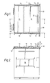
- a bin closure means comprising a movable lid element 10 and a fixed lid element 11.
- the movable lid element is wider than the fixed lid element and overlaps the fixed lid element by a sufficient amount to form a seal in the region where the lids overlap when the movable lid is in a closed position.
- the movable lid element includes a pair of sleeves 12, 13 welded to opposed marginal sections by way of intermediary flanges 14, 15.
- the sleeves are cylindrical tubes supported by cylindrical guides 16, 17 extending exteriorly of the bin in parallel inclined dispositions.
- the cylindrical guides 16, 17 are co-joined to a rectangular hollow channel framework 18 which sealingly rests on the upper peripheral lipped edge of the bin and is hinged to the bin by hinge joint 19.
- the movable lid element 10 includes a flat handle 20 extending perpendicularly from the lid for sliding the lid between an open and closed position, and a hollow profile rubber sealing strip 21 for sealing the interior of the bin when the movable lid element 10 is in a fully closed position.
- the rubber sealing strip 21 includes an end cap (not shown) on each end to ensure proper sealing.
- a security chain 32 which may be connected by a padlock to loop 33 to prevent unauthorised access to the bin should the waste comprise commercially sensitive material. Such a security chain is also useful in preventing unauthorized dumping in the bin.
- FIGURE NOS. 3 - 5 illustrate the bin closure means in more detail.
- like reference numerals to those used in FIGURE NOS. 1, 2, 6 and 7 refer to the same features.
- FIGURE NOS. 3 and 4 when the movable lid element 10 is in a fully retracted position, i.e. closed, the entire bin opening is tightly sealed.
- the rubber sealing strip 21 overlaps the support framework 18 at the closing edge and its hollow deformable profile avoids crushing of fingers or hands if they happen to be caught when the lid is being closed.
- the fully closed position of the movable lid element 10 is delimited by the end of the sleeves 12, 13 contacting flanges on the opening end of the framework 18.
- One of these flanges, viz flange 30, is depicted in FIGURE NOS. 4 and 6.
- the sleeves 12 extend lengthwise by a distance which is approximately two thirds of the width of the movable lid element 10, from the bin opening region. This enables the movable lid to be slid past the bin opening as shown in FIGURE NO. 5, thereby enabling a larger access to the interior of the bin than would otherwise be the case.
- the sleeves 12, 13 and their respective support guides 16, 17 are angled to enable the movable lid element 10 to clear the fixed lid element 11 when the movable lid element 10 is being manipulated between open and closed positions. This ensures that there is no frictional engagement between the lid elements and that easy operation is assured. It also ensures that the movable lid element 10 may be firmly seated on the framework 18 in its opposed marginal regions and against the upper surface of the leading edge of the fixed lid element 11 when the lid is closed.
- the hinge joint comprises one hollow pipe element 22 and two adjacent hollow pipe elements 23 with a pin 19 acting as a pivot through the elements.
- the purpose of the hinge joint 19 is to enable the entire bin closure means to pivot in an arc about the hinge when the bin is inverted for emptying by a waste removal vehicle, as illustrated in FIGURE NO. 8. Such an action may be initiated by fork-lifts of a waste removal vehicle being inserted into pockets on either side of the bin (one of which, viz 24, is illustrated in FIGURE NO. 2). The bin is then raised and upon rotation of the bin in a clockwise direction (as viewed in FIGURE NO. 2) the bin closure means swings away from its seating surface, due to gravity and the waste material falls out into the vehicle.
- a chain 31 connects the framework 18 to the interior of the bin to prevent the bin closure means swinging open more than the required amount. It also serves to prevent the framework 18 from being rotated through an arc to be back of the bin when the bin is in normal operation.
Landscapes
- Engineering & Computer Science (AREA)
- Mechanical Engineering (AREA)
- Refuse Receptacles (AREA)
- Closures For Containers (AREA)
Applications Claiming Priority (2)
| Application Number | Priority Date | Filing Date | Title |
|---|---|---|---|
| AU154/88 | 1988-08-31 | ||
| AUPJ015488 | 1988-08-31 |
Publications (1)
| Publication Number | Publication Date |
|---|---|
| EP0357209A1 true EP0357209A1 (de) | 1990-03-07 |
Family
ID=3773331
Family Applications (1)
| Application Number | Title | Priority Date | Filing Date |
|---|---|---|---|
| EP89307412A Withdrawn EP0357209A1 (de) | 1988-08-31 | 1989-07-20 | Deckel für Müllbehälter |
Country Status (4)
| Country | Link |
|---|---|
| US (1) | US4878596A (de) |
| EP (1) | EP0357209A1 (de) |
| CA (1) | CA1309699C (de) |
| NZ (1) | NZ229941A (de) |
Families Citing this family (22)
| Publication number | Priority date | Publication date | Assignee | Title |
|---|---|---|---|---|
| DK164219C (da) * | 1988-06-20 | 1992-10-26 | Busk Jensen Holding A S | Affaldscontainer til frontlaesning |
| US5092484A (en) * | 1990-06-04 | 1992-03-03 | Rubbermaid Commercial Products Inc. | Bin for granular substance |
| DE4129163C1 (de) * | 1991-09-02 | 1993-03-18 | Edelhoff Polytechnik Gmbh & Co, 5860 Iserlohn, De | |
| AP378A (en) * | 1993-02-26 | 1995-04-07 | Rural Ind Promotions Company Bw | Rubbish bin cover. |
| US5992680A (en) * | 1996-01-29 | 1999-11-30 | Smith; Philip E. | Slidable sealing lid apparatus for subsurface storage containers |
| US6364153B1 (en) * | 2000-10-27 | 2002-04-02 | Anthony D. Petzitillo, Jr. | Waste container with displaceable panel closure |
| US6732883B2 (en) | 2000-10-27 | 2004-05-11 | Wastequip Manufacturing Company | Waste container with displaceable panel closure |
| US6416098B1 (en) * | 2000-11-06 | 2002-07-09 | Motorola, Inc. | Satellite vehicle shipping container |
| US7010833B2 (en) * | 2003-07-18 | 2006-03-14 | Carlos Duarte | Slide hinge for spa cover |
| US7673769B2 (en) * | 2004-12-03 | 2010-03-09 | Rubbermaid Incorporated | Storage bin with moveable lid and attached scoop |
| US8578846B2 (en) * | 2008-11-03 | 2013-11-12 | Got Green?, LLC | Trash receptacle for collecting and compacting waste and related method of use |
| US7886660B1 (en) * | 2008-11-03 | 2011-02-15 | Sherwood Christopher R | System and trash receptacle for collecting and compacting trash |
| US20110062177A1 (en) * | 2009-09-13 | 2011-03-17 | Michael Ray | Portable storage box |
| EP2555999A4 (de) * | 2010-04-07 | 2015-01-21 | Warren Leonard Stone | Eimerdeckel und eimer damit |
| US9150353B2 (en) | 2012-08-01 | 2015-10-06 | Live Oak Intellectual Property, Llc | Wind-resistant container systems, anchoring systems, and methods of use |
| US8939318B2 (en) * | 2012-11-29 | 2015-01-27 | Nordson Corporation | Adhesive tank melter having sliding lid assembly |
| US10047018B2 (en) | 2016-03-09 | 2018-08-14 | Whirlpool Corporation | Composting device sliding lid with a seal assembly |
| US9895726B1 (en) | 2016-07-27 | 2018-02-20 | Whirlpool Corporation | Method for cleaning a food waste recycling bin of a food waste recycling appliance |
| USD1027351S1 (en) | 2016-03-09 | 2024-05-14 | Whirlpool Corporation | Food recycler |
| US20170305660A1 (en) * | 2016-04-20 | 2017-10-26 | Cody Brunelle | Roof accessible wear panel for aggregate delivery unit |
| CN111056330A (zh) * | 2019-12-18 | 2020-04-24 | 珠海格力智能装备有限公司 | 料仓及具有其的上料机构 |
| CN114348497A (zh) * | 2022-02-23 | 2022-04-15 | 新疆三吉隆环保科技有限责任公司 | 多功能垃圾分类收集站 |
Citations (4)
| Publication number | Priority date | Publication date | Assignee | Title |
|---|---|---|---|---|
| DE2454088A1 (de) * | 1973-07-23 | 1976-01-29 | Bock Norman | Muellbehaelter |
| US3951302A (en) * | 1974-08-05 | 1976-04-20 | Allan M. Hodge | Trash bin lid |
| US3961723A (en) * | 1974-07-12 | 1976-06-08 | Eckel Industries, Inc. | Receptacle with sliding cover |
| US4609117A (en) * | 1984-06-29 | 1986-09-02 | Industrial Containers (Aust.) Pty. Ltd. | Waste container |
Family Cites Families (5)
| Publication number | Priority date | Publication date | Assignee | Title |
|---|---|---|---|---|
| US1511613A (en) * | 1922-06-13 | 1924-10-14 | Joern William | Concrete refuse container |
| US4152979A (en) * | 1978-06-12 | 1979-05-08 | Blackwelders | Lid unit for a refuse compactor |
| US4456141A (en) * | 1981-11-19 | 1984-06-26 | Industrial Containers Pty. Ltd., Cnr. Moore | Waste containers |
| US4545523A (en) * | 1984-04-16 | 1985-10-08 | Galbreath Incorporated | Waste material handling container with liquid tight door seal |
| US4653662A (en) * | 1986-04-22 | 1987-03-31 | Pullman-Peabody, Inc. | Waste container with movable hatch lids |
-
1989
- 1989-01-06 US US07/293,963 patent/US4878596A/en not_active Expired - Fee Related
- 1989-07-14 NZ NZ229941A patent/NZ229941A/en unknown
- 1989-07-19 CA CA000606059A patent/CA1309699C/en not_active Expired - Lifetime
- 1989-07-20 EP EP89307412A patent/EP0357209A1/de not_active Withdrawn
Patent Citations (4)
| Publication number | Priority date | Publication date | Assignee | Title |
|---|---|---|---|---|
| DE2454088A1 (de) * | 1973-07-23 | 1976-01-29 | Bock Norman | Muellbehaelter |
| US3961723A (en) * | 1974-07-12 | 1976-06-08 | Eckel Industries, Inc. | Receptacle with sliding cover |
| US3951302A (en) * | 1974-08-05 | 1976-04-20 | Allan M. Hodge | Trash bin lid |
| US4609117A (en) * | 1984-06-29 | 1986-09-02 | Industrial Containers (Aust.) Pty. Ltd. | Waste container |
Also Published As
| Publication number | Publication date |
|---|---|
| CA1309699C (en) | 1992-11-03 |
| US4878596A (en) | 1989-11-07 |
| NZ229941A (en) | 1990-11-27 |
Similar Documents
| Publication | Publication Date | Title |
|---|---|---|
| US4878596A (en) | Waste bin lid | |
| US4609117A (en) | Waste container | |
| AU622536B2 (en) | Waste container | |
| US4836394A (en) | Refuse container with two-position lid | |
| US4456141A (en) | Waste containers | |
| US5150806A (en) | Refuse container with two-position lid | |
| US4186844A (en) | Easy opening trash bin lid | |
| US5984134A (en) | Trash container | |
| US5360132A (en) | Collecting container for waste | |
| US4913301A (en) | Refuse container | |
| US5381921A (en) | Refuse containers | |
| US5687881A (en) | Apparatus for conveying a solid particular material | |
| US5105967A (en) | Waste container lid system | |
| US8931655B2 (en) | Bin lid and bin incorporating same | |
| US6325587B1 (en) | Segregated waste collection system | |
| US3315828A (en) | Resilient closure latch for containers | |
| GB2109345A (en) | Doors for containers | |
| US4234096A (en) | Cover for waste container | |
| US4199075A (en) | Hinge structure for refuse containers | |
| US20030146230A1 (en) | Refuse container lid | |
| US5799825A (en) | Gate seal system | |
| AU600868B2 (en) | Waste bin lid | |
| EP0907585B1 (de) | Behälter mit bodenentleerung | |
| US6805257B2 (en) | Versatile lid system | |
| US4697836A (en) | Bin with retractable lid |
Legal Events
| Date | Code | Title | Description |
|---|---|---|---|
| PUAI | Public reference made under article 153(3) epc to a published international application that has entered the european phase |
Free format text: ORIGINAL CODE: 0009012 |
|
| AK | Designated contracting states |
Kind code of ref document: A1 Designated state(s): AT BE CH DE ES FR GB GR IT LI LU NL SE |
|
| 17P | Request for examination filed |
Effective date: 19900111 |
|
| 17Q | First examination report despatched |
Effective date: 19910527 |
|
| STAA | Information on the status of an ep patent application or granted ep patent |
Free format text: STATUS: THE APPLICATION HAS BEEN WITHDRAWN |
|
| 18W | Application withdrawn |
Withdrawal date: 19920313 |