EP0357227A1 - Drehverschluss - Google Patents
Drehverschluss Download PDFInfo
- Publication number
- EP0357227A1 EP0357227A1 EP89307736A EP89307736A EP0357227A1 EP 0357227 A1 EP0357227 A1 EP 0357227A1 EP 89307736 A EP89307736 A EP 89307736A EP 89307736 A EP89307736 A EP 89307736A EP 0357227 A1 EP0357227 A1 EP 0357227A1
- Authority
- EP
- European Patent Office
- Prior art keywords
- rotor
- detent
- turning
- actuator
- rotary nozzle
- Prior art date
- Legal status (The legal status is an assumption and is not a legal conclusion. Google has not performed a legal analysis and makes no representation as to the accuracy of the status listed.)
- Granted
Links
Images


Classifications
-
- B—PERFORMING OPERATIONS; TRANSPORTING
- B22—CASTING; POWDER METALLURGY
- B22D—CASTING OF METALS; CASTING OF OTHER SUBSTANCES BY THE SAME PROCESSES OR DEVICES
- B22D11/00—Continuous casting of metals, i.e. casting in indefinite lengths
- B22D11/10—Supplying or treating molten metal
-
- B—PERFORMING OPERATIONS; TRANSPORTING
- B22—CASTING; POWDER METALLURGY
- B22D—CASTING OF METALS; CASTING OF OTHER SUBSTANCES BY THE SAME PROCESSES OR DEVICES
- B22D41/00—Casting melt-holding vessels, e.g. ladles, tundishes, cups or the like
- B22D41/14—Closures
- B22D41/22—Closures sliding-gate type, i.e. having a fixed plate and a movable plate in sliding contact with each other for selective registry of their openings
- B22D41/26—Closures sliding-gate type, i.e. having a fixed plate and a movable plate in sliding contact with each other for selective registry of their openings characterised by a rotatively movable plate
Definitions
- the present invention relates to a rotary nozzle of the type which is attached to the bottom of a molten steel vessel, e.g., a laddle or tundish so that a sliding plate brick is rotated and the opening of a nozzle bore of a fixed plate brick is adjusted thereby controlling the pouring rate of molten steel, and more particularly the invention relates to a turning apparatus for a rotor which holds the sliding plate brick.
- Rotary nozzles have been used widely with laddles for receiving the molten steel tapped from a converter or the like to transport or to pour the molten steel into molds, tundishes for receiving the molten steel from a laddle to pour the molten steel into molds and the like.
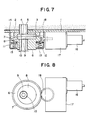
- Fig. 7 is a longitudinal sectional view showing schematically an example of a conventional rotary nozzle
- Fig. 8 is a bottom view of Fig. 7 with a part thereof being omitted.
- numeral 1 designates a shim plate mounted to the bottom of a laddle, tundish or the like
- 2 a base member attached to the shim plate and formed with a recess for mounting a fixed plate brick 3 therein and an opening into which a top nozzle 5 is fitted.
- Numeral 6 designates a rotor rotatably arranged on a movable member 11 through a ball bearing 12, formed with a recess in which a sliding plate brick 8 is mounted and an opening into which a bottom nozzle 10 is fitted and provided with a gear 7 on its upper outer periphery thereof.
- Numeral 13 designates a frame adapted to accommodate the rotor 6 and pivotably attached to the shim plate 1 by a hinge 14. It is to be noted that although not shown, the opposite side to the hinge 14 is secured to the shim member 1 with bolts, levers or the like.
- Numeral 15 designates springs mounted between the movable member 11 and the frame 13 and they are adapted to press the rotor 6 upward and force the sliding surface of the sliding plate brick 8 into close contact with the fixed plate brick 3.
- Numeral 16 designates a motor, 17 a reduction gear, and 18 the final-stage gear of the reduction gear 17 which is in mesh with the gear 7 of the rotor 6.
- the nozzle bores of the top nozzle 5, the fixed plate brick 3, the sliding plate brick 8 and the bottom nozzle 10 are located on the same center, and the nozzle bore 9 of the sliding plate brick 8 is in a wide-open position relative to the nozzle bore 4 of the fixed plate brick 3. Therefore, the molten steel in the laddle or the like is poured into a tundish or the like in the maximum amount.
- the motor 16 is operated so that the rotation reduced by the reduction gear 17 is transmitted to the rotor 6 through the gears 18 and 17, thereby rotating the rotor 6 through a desired angle. When this occurs, the opening of the nozzle bores 4 and 9 is adjusted to control the pouring rate of the molten steel.
- Rotary nozzles of this type have been recently used in large numbers owing to a number of advantages that the maintenance and inspection are easy, that the damages on the surfaces of the fixed plate brick 3 and the sliding plate brick 8 can be confirmed with the naked eye and they can also be replaced easily and so on.
- the driving unit for the rotor 6, that is, the motor 16 and the reduction gear 17 which are attached to the bottom of the laddle or the like are extremely large in size and weight thus making it inconvenient to handle.
- the present invention has been made to overcome the foregoing deficiencies and it is an object of the invention to provide a rotary nozzle equipped with a rotor driving unit which is small in size and light in weight.
- a rotary nozzle including a rotor formed with a plurality of notched engaging portions at equal intervals on its outer periphery, a turning member rotatably arranged along the rotor and including detent means adapted to engage with the engaging portions and a locking mechanism for bringing the detent means into and out of engagement with the engaging portions, and a hydraulic cylinder having an actuator connected to the turning member.
- a gear is formed on the outer periphery of the turning member, and the hydraulic cylinder is replaced with a rocking actuator whose output side is connected to a gear which in turn is connected to the gear of the turning member.
- a belt member having a lining on its inner surface is arranged on the outer periphery of the rotor in a manner that the ends of the belt member are attached to a connecting member having a function of tightening and loosing the belt member, and the connecting member is connected to the actuator of the hydraulic cylinder.
- Fig. 1 is a longitudinal sectional view of an embodiment of the present invention
- Fig. 2 is a sectional view taken along the line A-A of Fig. 1.
- Numeral 21 designates a ring portion provided on the upper outer periphery of a rotor 6 to be integral therewith and a plurality of notched engaging portions 22a to 22n are formed on its outer periphery at equal intervals (at intervals of 30 o in this embodiment).
- Numeral 23 designates a shuttle ring having a C sectional shape and formed on its inner periphery with a groove 24 rotatably loose-fitted on the ring portion 21 of the rotor 6.
- the shuttle ring 23 includes an arm 25 and an outwardly projecting convex portion 26 on the opposite side to the arm 25.
- Numeral 42 designates a hydraulic cylinder attached by a support arm 41 to one side of the convex portion 26 of the shuttle ring 23 (in this embodiment the convex portion 26 is arranged over an extent of about 60 o corresponding to the intervals of two of the engaging portions 22a to 22n).
- Numeral 44 designates a substantially Z-shaped lock member formed at its one end with a detent portion 45 for selectively engaging with the engaging portions 22a to 22n formed on the ring portion 21 and it is inserted into a slot 26a formed in the convex portion 26 with its substantially central portion being rotatably pivoted by a pin 46.
- the other end of the lock member 44 is pivotably connected to an actuator 43 of the hydraulic cylinder 42. It is to be noted that these component parts form a locking mechanism 40 for the rotor 6.
- Numeral 28 designates a hydraulic cylinder mounted on a shim plate 1 by a fixture 31 and its actuator 29 has its forward end pivotably connected to the arm 25 of the shuttle ring 23 by a pin 30. It is to be noted that these component parts form a driving mechanism 20 for the rotor 6.
- FIG. 2A there is illustrated a modification of the embodiment of Fig. 2.
- This modification features that differing from the engaging means and locking means of Fig. 2, its locking means brings into and out of engagement with the notched engaging portions 22a to 22n a detent portion formed at one end of a piston rod 84 of a piston 83 operated by a hydraulic cylinder 82 which is directly attached to the turning member.
- FIG. 3 there is illustrated another embodiment of the invention (corresponding to the sectional view taken along the line A-A of Fig. 1).
- This embodiment differs from the embodiment of Fig. 1 in that a gear 7 is formed on the ring portion 21 of the rotor 6, and also a substantially triangular rocker 50 formed on its sides with locking pawls 51 and 51a for engagement with the gear 7 of the rotor 6 is pivotably attached by a pivot pint 52 to the convex portion 26. It is to be noted that the rocker 50 is pressed from its sides by springs 53 and 53a, respectively, and the spring forces of the springs 53 and 53a are adjustable by a control mechanism (not shown). Note that a driving mechanism 20 is the same as the embodiment of Fig. 1.
- the rotor 6 can be rotated a wide range of angles in the direction of the arrow a or b thereby adjusting the degree of opening of the nozzle bores 4 and 9.
- Numeral 61 designates a belt member such as a steel belt wound on the outer periphery of the rotor 6 and its inner surface is provided with a lining 62 composed of a heat resisting material.
- Numeral 63 designates a substantially inverted Y-shaped connecting member whose body portion has its forward end pivotably connected to the actuator 29 of the hydraulic cylinder 28 by the pin 30 and its arms 64 and 64a secured to the ends of the belt member 61.
- Numeral 65 designates a hydraulic cylinder disposed in the body portion of the connecting member 63 and a rod 67 of its piston 66 is brought out from between the arms 64 and 64a of the connecting member 63 and has a friction member 68 composed of a heat resisting material attached to the forward end thereof.
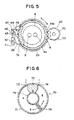
- Fig. 5 is a plan view of still another embodiment of the invention which differs from the embodiment of Fig. 1 in that while the locking mechanism 40 is the same as in the embodiment of Fig. 1, a gear 23a is formed on the outer peripheral portion of the shuttle ring 23 other than the convex portion 26 and a gear 7a is formed on the outer periphery of the rotor 6 in correspondence to the gear 23a.
- Numeral 70 designates a rocking actuator and its exemplary form is shown in Fig. 6.
- Numeral 71 designates a cylindrical body having a partition wall 72 formed therein and hydraulic ports 73 and 74 are formed on the sides of the partition wall 72 of the body 71.
- Numeral 75 designates a rotary member rotatably arranged in the central portion of the body 71 and including a vane 76.
- the outer periphery of the rotary member 75 and the forward end of the vane 76 are respectively in fluid-tight sliding contact with the partition wall 72 and the inner wall of the body 71 thereby forming chambers A and B.
- Numeral 77 designates a gear connected to the rotary member 75 of the rocking actuator 70 and in mesh with the gear 23a of the shuttle ring 23.
- the present invention is applied to a rotary nozzle of the construction shown in Fig. 1, the present invention is also applicable to rotary nozzle of other constructions, e.g., a rotary nozzle of the type in which a frame is fastened to a base member or a shim plate with bolts or the like or a dual hinged-type rotary nozzle in which both a base member and a frame are opened and closed hingedly.
- the hydraulic cylinders are used for the rotor driving mechanism and the locking mechanism, they may be replaced with air cylinders.
- the rocking actuator is not limited to the illustrated one and a rocking actuator of any other mechanism may be used.
- the present invention has the effect of providing a rotor driving mechanism which is not only simple in construction, small in size and light in weight but also low in cost.
Landscapes
- Engineering & Computer Science (AREA)
- Mechanical Engineering (AREA)
- Casting Support Devices, Ladles, And Melt Control Thereby (AREA)
Applications Claiming Priority (2)
| Application Number | Priority Date | Filing Date | Title |
|---|---|---|---|
| JP63200081A JPH0252165A (ja) | 1988-08-12 | 1988-08-12 | ロータリーノズル |
| JP200081/88 | 1988-08-12 |
Publications (2)
| Publication Number | Publication Date |
|---|---|
| EP0357227A1 true EP0357227A1 (de) | 1990-03-07 |
| EP0357227B1 EP0357227B1 (de) | 1992-09-30 |
Family
ID=16418536
Family Applications (1)
| Application Number | Title | Priority Date | Filing Date |
|---|---|---|---|
| EP89307736A Expired - Lifetime EP0357227B1 (de) | 1988-08-12 | 1989-07-28 | Drehverschluss |
Country Status (9)
| Country | Link |
|---|---|
| US (1) | US4998650A (de) |
| EP (1) | EP0357227B1 (de) |
| JP (1) | JPH0252165A (de) |
| KR (1) | KR900002867A (de) |
| BR (1) | BR8904056A (de) |
| CA (1) | CA1311612C (de) |
| DE (1) | DE68903080T2 (de) |
| ES (1) | ES2035570T3 (de) |
| ZA (1) | ZA895611B (de) |
Cited By (7)
| Publication number | Priority date | Publication date | Assignee | Title |
|---|---|---|---|---|
| GB2275009A (en) * | 1993-02-16 | 1994-08-17 | Bruehl Aluminiumtechnik | Hot metal container discharge outlet lock |
| BE1006674A5 (fr) * | 1992-01-29 | 1994-11-16 | Nippon Rotary Nozzle Co Ltd | Busette rotative. |
| GB2275010B (en) * | 1993-02-16 | 1996-09-25 | Bruehl Aluminiumtechnik | Process of filling a mould |
| CN1046644C (zh) * | 1990-07-04 | 1999-11-24 | 国际工业工程有限公司 | 改进的浇铸管引导和替换装置 |
| WO2000071953A1 (de) * | 1999-05-19 | 2000-11-30 | Sms Demag Ag | Verfahren und vorrichtung zum halten und abstechen von metallschmelzen |
| EP1698412A4 (de) * | 2003-12-24 | 2007-04-04 | Jfe Eng Corp | Vorrichtung zur steuerung der menge einer gegossenen metallschmelze |
| RU2484923C1 (ru) * | 2012-03-11 | 2013-06-20 | Научно-производственное республиканское унитарное предприятие "НПО "Центр" | Литейный ковш |
Families Citing this family (4)
| Publication number | Priority date | Publication date | Assignee | Title |
|---|---|---|---|---|
| JP2005262238A (ja) * | 2004-03-16 | 2005-09-29 | Jfe Engineering Kk | スライディングノズル装置及び注湯装置 |
| EP1707291A1 (de) * | 2005-03-10 | 2006-10-04 | Tech-Gate S.A. | Schiebeverschluss |
| JP5958566B2 (ja) * | 2015-01-16 | 2016-08-02 | 品川リフラクトリーズ株式会社 | スラブ連続鋳造用装置 |
| EP3424618B1 (de) * | 2017-07-05 | 2021-03-10 | Refractory Intellectual Property GmbH & Co. KG | Schiebeverschluss für ein metallschmelze enthaltendes gefäss |
Citations (5)
| Publication number | Priority date | Publication date | Assignee | Title |
|---|---|---|---|---|
| US3430644A (en) * | 1967-02-24 | 1969-03-04 | United States Steel Corp | Rotary gate for bottom pour vessel |
| US3780916A (en) * | 1971-12-17 | 1973-12-25 | United States Steel Corp | Rotary gate for bottom pour vessel having removable nozzles |
| FR2457141A1 (fr) * | 1979-05-25 | 1980-12-19 | Stopinc Ag | Dispositif de fermeture a obturateur rotatif pour recipients metallurgiques |
| FR2522554A1 (fr) * | 1982-03-05 | 1983-09-09 | Nippon Kokan Kk | Buse rotative du type a porte double, pour poche de coulee de fonte ou d'acier |
| EP0128841A1 (de) * | 1983-06-13 | 1984-12-19 | Nippon Kokan Kabushiki Kaisha | Klappen-Bauart einer Drehdüse |
Family Cites Families (1)
| Publication number | Priority date | Publication date | Assignee | Title |
|---|---|---|---|---|
| GB2133505B (en) * | 1982-12-14 | 1987-04-15 | Nippon Kokan Kk | Rotary nozzle system for metallurgical vessels |
-
1988
- 1988-08-12 JP JP63200081A patent/JPH0252165A/ja active Pending
-
1989
- 1989-07-17 US US07/381,120 patent/US4998650A/en not_active Expired - Fee Related
- 1989-07-20 CA CA000606176A patent/CA1311612C/en not_active Expired - Lifetime
- 1989-07-24 ZA ZA895611A patent/ZA895611B/xx unknown
- 1989-07-28 ES ES198989307736T patent/ES2035570T3/es not_active Expired - Lifetime
- 1989-07-28 EP EP89307736A patent/EP0357227B1/de not_active Expired - Lifetime
- 1989-07-28 DE DE8989307736T patent/DE68903080T2/de not_active Expired - Fee Related
- 1989-08-11 BR BR898904056A patent/BR8904056A/pt not_active IP Right Cessation
- 1989-08-12 KR KR1019890011526A patent/KR900002867A/ko not_active Withdrawn
Patent Citations (5)
| Publication number | Priority date | Publication date | Assignee | Title |
|---|---|---|---|---|
| US3430644A (en) * | 1967-02-24 | 1969-03-04 | United States Steel Corp | Rotary gate for bottom pour vessel |
| US3780916A (en) * | 1971-12-17 | 1973-12-25 | United States Steel Corp | Rotary gate for bottom pour vessel having removable nozzles |
| FR2457141A1 (fr) * | 1979-05-25 | 1980-12-19 | Stopinc Ag | Dispositif de fermeture a obturateur rotatif pour recipients metallurgiques |
| FR2522554A1 (fr) * | 1982-03-05 | 1983-09-09 | Nippon Kokan Kk | Buse rotative du type a porte double, pour poche de coulee de fonte ou d'acier |
| EP0128841A1 (de) * | 1983-06-13 | 1984-12-19 | Nippon Kokan Kabushiki Kaisha | Klappen-Bauart einer Drehdüse |
Cited By (10)
| Publication number | Priority date | Publication date | Assignee | Title |
|---|---|---|---|---|
| CN1046644C (zh) * | 1990-07-04 | 1999-11-24 | 国际工业工程有限公司 | 改进的浇铸管引导和替换装置 |
| BE1006674A5 (fr) * | 1992-01-29 | 1994-11-16 | Nippon Rotary Nozzle Co Ltd | Busette rotative. |
| GB2275009A (en) * | 1993-02-16 | 1994-08-17 | Bruehl Aluminiumtechnik | Hot metal container discharge outlet lock |
| GB2275010B (en) * | 1993-02-16 | 1996-09-25 | Bruehl Aluminiumtechnik | Process of filling a mould |
| GB2275009B (en) * | 1993-02-16 | 1996-09-25 | Bruehl Aluminiumtechnik | Hot metal container discharge outlet lock |
| ES2112686A1 (es) * | 1993-02-16 | 1998-04-01 | Bruehl Aluminiumtechnik | Cierre de abertura de vaciado |
| WO2000071953A1 (de) * | 1999-05-19 | 2000-11-30 | Sms Demag Ag | Verfahren und vorrichtung zum halten und abstechen von metallschmelzen |
| EP1698412A4 (de) * | 2003-12-24 | 2007-04-04 | Jfe Eng Corp | Vorrichtung zur steuerung der menge einer gegossenen metallschmelze |
| US7546937B2 (en) | 2003-12-24 | 2009-06-16 | Jfe Engineering Corporation | Poured molten metal quantity control device |
| RU2484923C1 (ru) * | 2012-03-11 | 2013-06-20 | Научно-производственное республиканское унитарное предприятие "НПО "Центр" | Литейный ковш |
Also Published As
| Publication number | Publication date |
|---|---|
| JPH0252165A (ja) | 1990-02-21 |
| DE68903080D1 (de) | 1992-11-05 |
| DE68903080T2 (de) | 1993-04-08 |
| ES2035570T3 (es) | 1993-04-16 |
| ZA895611B (en) | 1990-04-25 |
| EP0357227B1 (de) | 1992-09-30 |
| US4998650A (en) | 1991-03-12 |
| CA1311612C (en) | 1992-12-22 |
| BR8904056A (pt) | 1990-03-20 |
| KR900002867A (ko) | 1990-03-23 |
Similar Documents
| Publication | Publication Date | Title |
|---|---|---|
| EP0357227B1 (de) | Drehverschluss | |
| CA1232892A (en) | Mechanism for actuating a proportioning valve | |
| GB2093944A (en) | Continuous ratchet drive | |
| US5076166A (en) | Arrangement for the accurately positioned quick-action clamping and tensioning of printing plates | |
| CN88101608A (zh) | 开关活门驱动装置 | |
| JPH0335481Y2 (de) | ||
| CA2242501C (en) | Sliding gate valve for a vessel containing molten metal | |
| JPS5941263A (ja) | 長手方向に往復運動可能なドクタを振動運動させるための装置 | |
| KR900007959B1 (ko) | 슬라이딩 게이트 밸브 | |
| US4235567A (en) | Material handling machine with adjustable speed-power relationship for boom movement | |
| CA2059133A1 (fr) | Dispositif de commande du declenchement temporise d'un mecanisme | |
| GB2040024A (en) | Closure valve for the outlet aperture of a container for loose material | |
| JP4040472B2 (ja) | 貨物船のハッチカバー開閉装置の固定機構 | |
| FI71836B (fi) | Foer reglering av gjutning fraon ugnstapphaol laemplig ventil | |
| EP1001201B1 (de) | Verriegelbarer Hebelmechanismus | |
| CN115666818B (zh) | 冶金容器的浇口处的滑动式封闭件 | |
| GB2149888A (en) | Sliding gate valves | |
| US5473970A (en) | Interlocking change-over valve system | |
| SU1574872A1 (ru) | Механизм газораспределени двигател внутреннего сгорани с регулируемыми фазами | |
| US5842619A (en) | Device for controlling the discharge of heavy material from a container | |
| EP0130205A1 (de) | Bewegungsmechanismus um verschiedene bewegungen aus einer motoreinheit zu erhalten | |
| US4457459A (en) | Valve suitable for controlling teeming from furnace tapholes | |
| CS277070B6 (en) | Device for the control of printing pressures | |
| US3358859A (en) | Material handling apparatus | |
| JPH0121253Y2 (de) |
Legal Events
| Date | Code | Title | Description |
|---|---|---|---|
| PUAI | Public reference made under article 153(3) epc to a published international application that has entered the european phase |
Free format text: ORIGINAL CODE: 0009012 |
|
| AK | Designated contracting states |
Kind code of ref document: A1 Designated state(s): BE DE ES FR GB GR IT |
|
| 17P | Request for examination filed |
Effective date: 19900820 |
|
| 17Q | First examination report despatched |
Effective date: 19911212 |
|
| GRAA | (expected) grant |
Free format text: ORIGINAL CODE: 0009210 |
|
| AK | Designated contracting states |
Kind code of ref document: B1 Designated state(s): BE DE ES FR GB GR IT |
|
| PG25 | Lapsed in a contracting state [announced via postgrant information from national office to epo] |
Ref country code: GR Free format text: LAPSE BECAUSE OF FAILURE TO SUBMIT A TRANSLATION OF THE DESCRIPTION OR TO PAY THE FEE WITHIN THE PRESCRIBED TIME-LIMIT Effective date: 19920930 |
|
| REF | Corresponds to: |
Ref document number: 68903080 Country of ref document: DE Date of ref document: 19921105 |
|
| ITF | It: translation for a ep patent filed | ||
| ET | Fr: translation filed | ||
| REG | Reference to a national code |
Ref country code: ES Ref legal event code: FG2A Ref document number: 2035570 Country of ref document: ES Kind code of ref document: T3 |
|
| PG25 | Lapsed in a contracting state [announced via postgrant information from national office to epo] |
Ref country code: ES Free format text: LAPSE BECAUSE OF THE APPLICANT RENOUNCES Effective date: 19930729 |
|
| PLBE | No opposition filed within time limit |
Free format text: ORIGINAL CODE: 0009261 |
|
| STAA | Information on the status of an ep patent application or granted ep patent |
Free format text: STATUS: NO OPPOSITION FILED WITHIN TIME LIMIT |
|
| 26N | No opposition filed | ||
| PGFP | Annual fee paid to national office [announced via postgrant information from national office to epo] |
Ref country code: FR Payment date: 19950711 Year of fee payment: 7 |
|
| PGFP | Annual fee paid to national office [announced via postgrant information from national office to epo] |
Ref country code: GB Payment date: 19950717 Year of fee payment: 7 |
|
| PGFP | Annual fee paid to national office [announced via postgrant information from national office to epo] |
Ref country code: DE Payment date: 19950725 Year of fee payment: 7 |
|
| PGFP | Annual fee paid to national office [announced via postgrant information from national office to epo] |
Ref country code: BE Payment date: 19950911 Year of fee payment: 7 |
|
| PG25 | Lapsed in a contracting state [announced via postgrant information from national office to epo] |
Ref country code: GB Effective date: 19960728 |
|
| PG25 | Lapsed in a contracting state [announced via postgrant information from national office to epo] |
Ref country code: BE Effective date: 19960731 |
|
| BERE | Be: lapsed |
Owner name: TOKYO YOGYO K.K. Effective date: 19960731 Owner name: KOKAN KIKAI KOGYO K.K. Effective date: 19960731 Owner name: NKK CORP. Effective date: 19960731 Owner name: NIPPON ROTARY NOZZLE CO. LTD Effective date: 19960731 |
|
| GBPC | Gb: european patent ceased through non-payment of renewal fee |
Effective date: 19960728 |
|
| PG25 | Lapsed in a contracting state [announced via postgrant information from national office to epo] |
Ref country code: FR Effective date: 19970328 |
|
| PG25 | Lapsed in a contracting state [announced via postgrant information from national office to epo] |
Ref country code: DE Effective date: 19970402 |
|
| REG | Reference to a national code |
Ref country code: FR Ref legal event code: ST |
|
| REG | Reference to a national code |
Ref country code: ES Ref legal event code: FD2A Effective date: 20001102 |
|
| PG25 | Lapsed in a contracting state [announced via postgrant information from national office to epo] |
Ref country code: IT Free format text: LAPSE BECAUSE OF NON-PAYMENT OF DUE FEES;WARNING: LAPSES OF ITALIAN PATENTS WITH EFFECTIVE DATE BEFORE 2007 MAY HAVE OCCURRED AT ANY TIME BEFORE 2007. THE CORRECT EFFECTIVE DATE MAY BE DIFFERENT FROM THE ONE RECORDED. Effective date: 20050728 |