EP0357274A2 - Schaltknüppel zur mehrachsigen Steuerung - Google Patents
Schaltknüppel zur mehrachsigen Steuerung Download PDFInfo
- Publication number
- EP0357274A2 EP0357274A2 EP89308147A EP89308147A EP0357274A2 EP 0357274 A2 EP0357274 A2 EP 0357274A2 EP 89308147 A EP89308147 A EP 89308147A EP 89308147 A EP89308147 A EP 89308147A EP 0357274 A2 EP0357274 A2 EP 0357274A2
- Authority
- EP
- European Patent Office
- Prior art keywords
- lever
- energy
- shift pattern
- actuated
- relative
- Prior art date
- Legal status (The legal status is an assumption and is not a legal conclusion. Google has not performed a legal analysis and makes no representation as to the accuracy of the status listed.)
- Withdrawn
Links
- 230000033001 locomotion Effects 0.000 claims abstract description 26
- 230000003405 preventing effect Effects 0.000 claims abstract description 7
- 230000004044 response Effects 0.000 claims abstract description 6
- 230000007935 neutral effect Effects 0.000 claims description 10
- 235000014676 Phragmites communis Nutrition 0.000 description 4
- 230000000295 complement effect Effects 0.000 description 3
- 238000010586 diagram Methods 0.000 description 3
- 230000004048 modification Effects 0.000 description 3
- 238000012986 modification Methods 0.000 description 3
- 230000006835 compression Effects 0.000 description 2
- 238000007906 compression Methods 0.000 description 2
- BYHQTRFJOGIQAO-GOSISDBHSA-N 3-(4-bromophenyl)-8-[(2R)-2-hydroxypropyl]-1-[(3-methoxyphenyl)methyl]-1,3,8-triazaspiro[4.5]decan-2-one Chemical compound C[C@H](CN1CCC2(CC1)CN(C(=O)N2CC3=CC(=CC=C3)OC)C4=CC=C(C=C4)Br)O BYHQTRFJOGIQAO-GOSISDBHSA-N 0.000 description 1
- 241001124569 Lycaenidae Species 0.000 description 1
- 230000002411 adverse Effects 0.000 description 1
- 230000000712 assembly Effects 0.000 description 1
- 238000000429 assembly Methods 0.000 description 1
- 230000005540 biological transmission Effects 0.000 description 1
- 239000002131 composite material Substances 0.000 description 1
- 238000010276 construction Methods 0.000 description 1
- 239000000428 dust Substances 0.000 description 1
- 230000007613 environmental effect Effects 0.000 description 1
- 239000003337 fertilizer Substances 0.000 description 1
- 238000003306 harvesting Methods 0.000 description 1
- 239000004009 herbicide Substances 0.000 description 1
- 239000000463 material Substances 0.000 description 1
- 230000008520 organization Effects 0.000 description 1
- 239000000575 pesticide Substances 0.000 description 1
- 238000007747 plating Methods 0.000 description 1
- 230000002028 premature Effects 0.000 description 1
- 230000007704 transition Effects 0.000 description 1
Images
Classifications
-
- H—ELECTRICITY
- H01—ELECTRIC ELEMENTS
- H01H—ELECTRIC SWITCHES; RELAYS; SELECTORS; EMERGENCY PROTECTIVE DEVICES
- H01H25/00—Switches with compound movement of handle or other operating part
- H01H25/04—Operating part movable angularly in more than one plane, e.g. joystick
-
- F—MECHANICAL ENGINEERING; LIGHTING; HEATING; WEAPONS; BLASTING
- F16—ENGINEERING ELEMENTS AND UNITS; GENERAL MEASURES FOR PRODUCING AND MAINTAINING EFFECTIVE FUNCTIONING OF MACHINES OR INSTALLATIONS; THERMAL INSULATION IN GENERAL
- F16H—GEARING
- F16H59/00—Control inputs to control units of change-speed- or reversing-gearings for conveying rotary motion
- F16H59/02—Selector apparatus
- F16H59/04—Ratio selector apparatus
- F16H59/044—Ratio selector apparatus consisting of electrical switches or sensors
-
- Y—GENERAL TAGGING OF NEW TECHNOLOGICAL DEVELOPMENTS; GENERAL TAGGING OF CROSS-SECTIONAL TECHNOLOGIES SPANNING OVER SEVERAL SECTIONS OF THE IPC; TECHNICAL SUBJECTS COVERED BY FORMER USPC CROSS-REFERENCE ART COLLECTIONS [XRACs] AND DIGESTS
- Y10—TECHNICAL SUBJECTS COVERED BY FORMER USPC
- Y10T—TECHNICAL SUBJECTS COVERED BY FORMER US CLASSIFICATION
- Y10T74/00—Machine element or mechanism
- Y10T74/20—Control lever and linkage systems
- Y10T74/20012—Multiple controlled elements
- Y10T74/20201—Control moves in two planes
Definitions
- the present invention is directed generally to apparatus for representing a plurality of positions of an element in digital logic form and more particularly to such an apparatus adapted for use with a joystick-type of shift lever arrangement for providing a digital logic representation of the position of a shift lever relative to a given shift pattern.
- Joystick-type control levers are utilized in many applications, including relatively simple video game devices, as well as relatively more demanding machinery control applications. Such control applications may include the control of industrial machinery and/or gear shift levers for both off-road and on-road vehicles.
- the shift levers In such industrial and vehicular applications, the shift levers must be very rugged and reliable in operation over a relatively long service life. These relatively rugged assemblies must continue to operate reliably in spite of adverse environmental conditions which might be encountered, whether it be on the factory floor, or in on-road or off-road vehicular applications.
- the assignee of the present application has also developed a number of novel electronic and/or microcomputer-based control systems for various agricultural or other on-road and off-road vehicles and/or other machinery applications. Accordingly, it is also desirable to provide a joystick controller which is capable of simply and readily interfacing with existing control systems to provide an easy-to-use digital logic representation of the position of the shift lever with respect to a given shift pattern.
- a joystick controller apparatus in accordance with the invention comprises a lever; mounting means for mounting said lever for pivotal motion in at least two directions; guide means defining a preselected shift pattern for said lever; and indicating means for producing a digital logic representation of the position of said lever relative to said shift pattern; said indicating means comprising energy actuated means positioned at predetermined locations relative to the shift pattern, energy producing means positioned in registry with the energy actuated means for normally actuating the same, and shield means interposed between the energy producing means and energy actuated means and movable in response to movement of said lever into positions for respectively permitting and preventing actuation of the energy actuated means by the energy producing means in a predetermined fashion such that said energy actuated means collectively form a representation of the location of said lever relative to said shift pattern.
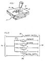
- a joystick controller is indicated generally by reference numeral 10.
- this joystick controller includes a joystick or lever 12 which is movable in at least two orthogonal directions 14, 16.
- a guide plate or guide means 18 defines a preselected shift pattern 20 which is turn defines a number of discrete possible positions of movement of the joystick with respect to the orthogonal axes or directions 14, 16.
- the illustrated shift pattern is generally a double-H configuration defining essentially nine positions for shift lever 12.
- other shift patterns may be utilized without departing from the invention, the illustrated pattern being by way of illustration only.
- a position indicating means 30, shown in circuit schematic form in Fig. 3, is adapted to respond to the position of the lever 12 relative to the shift pattern 20 for producing a digital logic representation of this position.
- this digital logic representation comprises a composite electrical signal produced on a series of output terminals 32 in response to a given pattern of actuated and non-actuated switches, designated generally by reference numeral 34. That is, these switches or other similar switching means 34 are arranged in such a manner as to be actuated or non-actuated in predetermined sequences or patterns, so as to provide a plurality of distinct sequences or patterns representative of the plurality of possible positions of the lever 12 relative to the shift pattern 20.
- Respective input terminals 35 of the switches may be coupled to any convenient reference voltage.
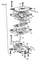
- the position indicating means takes the form of a plurality of energy actuated means, such as a magnetically actuated reed switch 40. Only one such reed switch 40 has been illustrated for purposes of description, it being understood that a plurality of such switches 40, corresponding in number to the switches 34 illustrated schematically in Fig. 3, are utilized in the illustrated embodiment.
- These energy actuated means or switches 40 are positioned at predetermined locations relative to the shift pattern 20. In the illustrated embodiment, this is accomplished by providing a switch mounting block member 42 which is formed with a plurality of recesses or cavities designated generally by reference numeral 44 at predetermined locations thereon relative to the shift pattern 20. Each of these cavities 44 is of complementary shape for mounting therewithin one of the reed switches or other energy actuated means 40.
- the position indicating means utilizes a plurality of energy producing means such as magnets 50 which are, like the switches 40 mounted or positioned at predetermined locations relative to the shift pattern.
- a magnet mounting block 52 is similarly provided with a plurality of recesses or cavities 54 each being of complimentary configuration for receiving and mounting one of the magnets 50, it being understood that although only one of the magnets 50 has been illustrated herein, one such magnet 50 is provided in each cavity 54.
- the cavities 54, and hence the magnets 50 are aligned in a predetermined pattern relative to the cavities or recesses 44 and reed switches or other energy actuated devices 40, such that the energy producing means 50 would normally actuate the energy actuated means 40.
- a further shield member or shield means which here takes the form of a pair of metallic plate-like shield members 60, 62 is interposed between the energy producing means and energy actuated means. These shield means are located and configured for movement into respective positions for alternatively permitting or preventing the actuation of the latter by the former.
- These shield means or members 60, 62 are generally coupled or otherwise mounted for movement in response to movement of the lever 12 in a predetermined fashion to cause the aforesaid movement of the shields between positions for respectively preventing and permitting actuation of the various ones of switches 40 by the associated magnets 50.
- the switches or other energy actuated means 40 generally correspond to the switches indicated in the schematic diagram of Fig. 3.
- the switches are here designated at forward (F), reverse (R), + and -, which are located at generally north, south, east and west locations relative to the plane defined by guide plate 18 and the orthogonal directions of movement 14, 16 indicated in Fig. 1.
- a neutral switch (N) and a safety switch (S) are provided.
- the shift lever or joystick 12 is mounted to an elongate shaft 70, which shaft is in turn pivotally mounted for pivotal motion in two orthogonal directions.
- a first generally U-shaped yoke-like member 72 is pivotally mounted by a pivot pin 74 which extends through a block 76.
- the block 76 is in turn mounted for pivotal motion about an axis defined by a transverse pivot pin or shaft 78.
- This latter shaft 78 extends at right angles to shaft 74 and is received in a pair of end mounting blocks 80, 82.
- These latter mounting blocks 80 and 82 are preferably mounted to a base plate 84 by suitable means such as threaded fasteners 86 (only one pair illustrated).
- the pivotal motion of the block 76 is limited by a pair of detenting indexing blocks 90, 92 which are mounted to the plate 84 preferably using the same fasteners 86 as the respective blocks 80, 82.
- These latter indexing blocks have central detent slots or recesses for normally receiving a second set of outwardly extending locking pins or shaft members 94, 96 which are generally spaced from and parallel with the shaft 78.
- the shaft 78 is mounted to the respective blocks 80, 82 in a spring-loaded arrangement.
- This arrangement includes a pair of elongate generally vertically extending mounting slots 102, 104 in the respective mounting blocks 80, 82, each of which mounts a coil compression spring 106, 108 which bears against an underside of one of the respective ends of shaft 78.
- the lower locking pins 94, 96 may be released from the detent slots to permit pivotal motion of the block 76 about the axis of shaft 78 by downward pressure upon the shift lever 12 and hence of shaft 78 against the opposing force of the respective compression springs 106, 108.
- the respective locking members 90, 92 have ramp-like surfaces leading up to their central detenting recesses to accommodate and guide the movement of pins 94, 96 as the block 76 pivots about the axis of shaft 78.
- a further torsion spring 95 is provided, in the preferred embodiment.
- the torsion spring 95 is wound around a spool-like member 97 extending from the side of yoke 72. Opposite free ends of torsion spring 95 abut respective pins 99, 101 which extend respectively from yoke 72 and block 76.
- each is provided with a plurality of through apertures which correspond in a predetermined fashion to the arrangement of the respective magnets 50 and switches 40.
- the plate 60 is designated generally as the +, - member and has a pair of through apertures 120, 122 which are generally alignable with the respective + and - recesses 44 and hence with the switches 40 to be mounted therein.
- This shield 60 is a relatively thin, flat plate-like member and has an elongate centrally located slot 124 for receiving the shaft 70 therethrough.
- a complementary shaped recess 125 is formed for receiving the plate 60 on the underside of the switch mounting plate or block 42, such that the plate 60 may slide in the + and - direction as indicated by the arrow in Fig. 2 but is restrained from movement in the forward (F) and reverse (R) directions, as indicated adjacent shield or plate member 62. It will be seen that the alignment of slot 124 will permit free movement of the shaft 70 relative to the plate in the forward and reverse direction and cause the plate 60 to move in unison with the shaft 70 as the latter is moved in the + and - direction.
- the second shield member 62 is a similar relatively thin, flat plate-like member having a plurality of through apertures designated generally by reference numeral 130 which are respectively aligned for alternatively shielding and exposing respective ones of the switches 40 with respect to their associated magnets 50.
- This plate includes an elongate slot 134 for receiving shaft 70 therethrough and a complementary spaced recess 136 is provided in the magnet mounting block 52 for slidably receiving the shield or plate member 62 therewithin. Accordingly, the shield or plate member is free to slide in the forward (F) and reverse (R) directions as indicated in the associated arrows in Fig. 2 but is restrained from moving in the + and - directions. Similarly, the shaft 70 is free to move in the + and - directions relative to the plate or shield 62, but carries the plate or shield 62 with it as it is moved in the forward (F) and reverse (R) directions.
- all of the switches 40 are normally open switches which are activated in a predetermined sequence or pattern to define the joystick positions.
- the forward switch will activate as the joystick is moved to the forward (F) position and will stay continuously in its active or closed state as the joystick is moved in either the + or - positions while remaining in the forward position (F/+ and F/-).
- the neutral switch will be activated as the joystick is moved to the central or neutral position and will remain closed as the joystick is moved toward either the + or - positions (N/+ and N/-).
- the reverse switch will activate as the joystick is moved to the reverse position and will stay in the closed state as the joystick is moved toward the R/+ or R/- positions.
- the + switch will activate as the joystick is moved to the + position and will be in the closed state whenever the joystick is in any of the F/+, N/+ or R/+ positions.
- the - switch will activate at any time the joystick is moved to any of the negative positions F/-, N/- and R/-.
- the safety switch is generally placed such that it is activated while the joystick is in transition between either of the forward and reverse positions and the neutral position or vice-versa.
- the safety switch may be utilized as an additional interlock feature to prevent actuation of any associated transmission or other device being controlled by the joystick until the joystick is fully moved from one position to another.
- the neutral switch may also be additionally used as a start up indicator or control if desired.
- the forward, reverse, + and - switches are each provided with a pair of resistor elements, one in series with the switch and one in parallel with the switch.
- These resistor elements, for example 140, 142 with respect to the forward switch are used in the illustrated embodiment to provide a series of readable voltages at the output end 32, which voltages will be indicative of the state of the respective switches.
- terminal at 32 will "see" the sum of the resistances of resistors 140 and 142, which if placed in series with some further input impedance or resistor from terminal 32 to ground, for example will produce a first, predicable voltage drop when the values of all of the resistors are known.
Landscapes
- Engineering & Computer Science (AREA)
- General Engineering & Computer Science (AREA)
- Mechanical Engineering (AREA)
- Mechanical Control Devices (AREA)
- Control Of Transmission Device (AREA)
Applications Claiming Priority (2)
| Application Number | Priority Date | Filing Date | Title |
|---|---|---|---|
| US241027 | 1981-03-06 | ||
| US07/241,027 US4926172A (en) | 1988-09-02 | 1988-09-02 | Joystick controller |
Publications (2)
| Publication Number | Publication Date |
|---|---|
| EP0357274A2 true EP0357274A2 (de) | 1990-03-07 |
| EP0357274A3 EP0357274A3 (de) | 1991-02-06 |
Family
ID=22908947
Family Applications (1)
| Application Number | Title | Priority Date | Filing Date |
|---|---|---|---|
| EP19890308147 Withdrawn EP0357274A3 (de) | 1988-09-02 | 1989-08-10 | Schaltknüppel zur mehrachsigen Steuerung |
Country Status (5)
| Country | Link |
|---|---|
| US (1) | US4926172A (de) |
| EP (1) | EP0357274A3 (de) |
| AU (1) | AU617841B2 (de) |
| BR (1) | BR8904421A (de) |
| CA (1) | CA1319880C (de) |
Cited By (11)
| Publication number | Priority date | Publication date | Assignee | Title |
|---|---|---|---|---|
| EP0731293A1 (de) * | 1995-03-06 | 1996-09-11 | Magneti Marelli France | Steuerhebelanordnung, insbesondere für automatisiertes mechanisches Schaltgetriebe |
| GB2315545A (en) * | 1996-07-17 | 1998-02-04 | Onofrio Antonio Aisner D | Gear stick position indicator |
| EP1036959A1 (de) * | 1999-03-15 | 2000-09-20 | United Parts France SA | Vorrichtung zur schrittweisen Schaltsteuerung eines Getriebes |
| DE202005020462U1 (de) * | 2005-12-08 | 2007-04-19 | Liebherr-Werk Ehingen Gmbh | Kran |
| EP1995496A1 (de) * | 2007-05-21 | 2008-11-26 | Magneti Marelli Powertrain S.p.A. | Druckknopf-Steuerungssystem für eine servomechanische Gangschaltung |
| WO2010066789A1 (en) * | 2008-12-10 | 2010-06-17 | Ambu A/S | Endoscope bending section control mechanism |
| GB2468293A (en) * | 2009-03-03 | 2010-09-08 | Nissan Motor Mfg | Shift by wire gear shift apparatus having a manual H shift pattern |
| EP1815594B1 (de) * | 2004-11-24 | 2014-01-08 | ZF FRIEDRICHSHAFEN Aktiengesellschaft | Schaltvorrichtung für ein kraftfahrzeug |
| US11166627B2 (en) | 2018-01-26 | 2021-11-09 | Ambu A/S | Method for fixation of a wire portion of an endoscope, and an endoscope |
| US11291355B2 (en) | 2018-01-19 | 2022-04-05 | Ambu A/S | Method for fixation of a wire portion of an endoscope, and an endoscope |
| DE102021129334A1 (de) | 2021-11-11 | 2023-05-11 | Bayerische Motoren Werke Aktiengesellschaft | Bedienelement für ein Kraftfahrzeug, insbesondere für ein Kraftrad oder ein motorisiertes Dreirad, sowie Kraftfahrzeug |
Families Citing this family (43)
| Publication number | Priority date | Publication date | Assignee | Title |
|---|---|---|---|---|
| US5225831A (en) * | 1991-06-04 | 1993-07-06 | Osborn Jeffrey S | Joystick and control circuit therefor |
| US5325083A (en) * | 1992-05-01 | 1994-06-28 | Chrysler Corporation | Manual valve position sensing system |
| US5388476A (en) * | 1993-06-15 | 1995-02-14 | Agco Corporation | Gearshift mechanism |
| US5406860A (en) * | 1993-12-01 | 1995-04-18 | Deere & Company | Transmission shift lever assembly |
| US6232789B1 (en) | 1997-05-28 | 2001-05-15 | Cascade Microtech, Inc. | Probe holder for low current measurements |
| US6170606B1 (en) * | 1996-06-28 | 2001-01-09 | Safety Dynamicon, Inc. | Analog control |
| US5875682A (en) * | 1997-03-20 | 1999-03-02 | Caterpillar Inc. | Operator controlled electrical output signal device |
| JP3167958B2 (ja) * | 1997-05-08 | 2001-05-21 | コナミ株式会社 | 多方向切替操作装置 |
| US6072390A (en) * | 1999-03-31 | 2000-06-06 | Daimlerchrysler Corporation | Position sensing system for manually operated shift lever of a vehicle transmission |
| EP1126354B1 (de) * | 1999-08-10 | 2011-03-30 | Hosiden Corporation | Multidirektionelle eingabevorrichtung |
| JP4572027B2 (ja) * | 1999-11-05 | 2010-10-27 | 現代自動車株式会社 | 変速レバーユニット用ディテントメカニズム |
| DE20114544U1 (de) | 2000-12-04 | 2002-02-21 | Cascade Microtech, Inc., Beaverton, Oreg. | Wafersonde |
| JP2002312047A (ja) * | 2001-04-16 | 2002-10-25 | Alps Electric Co Ltd | 手動入力装置 |
| JP2005527823A (ja) | 2002-05-23 | 2005-09-15 | カスケード マイクロテック インコーポレイテッド | デバイスのテスト用プローブ |
| US6724205B1 (en) | 2002-11-13 | 2004-04-20 | Cascade Microtech, Inc. | Probe for combined signals |
| US20040130525A1 (en) * | 2002-11-19 | 2004-07-08 | Suchocki Edward J. | Dynamic touch screen amusement game controller |
| US7057404B2 (en) | 2003-05-23 | 2006-06-06 | Sharp Laboratories Of America, Inc. | Shielded probe for testing a device under test |
| JP4774191B2 (ja) * | 2003-07-31 | 2011-09-14 | 株式会社バンダイナムコゲームス | 操作レバー装置 |
| US7427868B2 (en) | 2003-12-24 | 2008-09-23 | Cascade Microtech, Inc. | Active wafer probe |
| JP4327004B2 (ja) * | 2004-04-15 | 2009-09-09 | アルプス電気株式会社 | 多方向入力装置 |
| US8506386B2 (en) * | 2004-07-16 | 2013-08-13 | Rocket Gaming Systems, Llc | Method and apparatus for awarding wins for game play |
| US7199316B2 (en) * | 2004-09-10 | 2007-04-03 | W.T. Storey, Inc. | Multifunction switch for operating a device in a sealed container |
| DE202005021435U1 (de) | 2004-09-13 | 2008-02-28 | Cascade Microtech, Inc., Beaverton | Doppelseitige Prüfaufbauten |
| US7535247B2 (en) | 2005-01-31 | 2009-05-19 | Cascade Microtech, Inc. | Interface for testing semiconductors |
| US7656172B2 (en) | 2005-01-31 | 2010-02-02 | Cascade Microtech, Inc. | System for testing semiconductors |
| US7828658B2 (en) * | 2005-03-15 | 2010-11-09 | Rocket Gaming Systems, Llc | Player actuated input for a gaming machine |
| US7641552B2 (en) * | 2005-03-15 | 2010-01-05 | Rocket Gaming Systems, Llc | Player actuated input for a gaming machine |
| US7449899B2 (en) | 2005-06-08 | 2008-11-11 | Cascade Microtech, Inc. | Probe for high frequency signals |
| EP1932003A2 (de) | 2005-06-13 | 2008-06-18 | Cascade Microtech, Inc. | Breitbandige aktiv-passiv-differenzsignalsonde |
| DE112007001399T5 (de) | 2006-06-09 | 2009-05-07 | Cascade Microtech, Inc., Beaverton | Messfühler für differentielle Signale mit integrierter Symmetrieschaltung |
| US7723999B2 (en) | 2006-06-12 | 2010-05-25 | Cascade Microtech, Inc. | Calibration structures for differential signal probing |
| US7764072B2 (en) | 2006-06-12 | 2010-07-27 | Cascade Microtech, Inc. | Differential signal probing system |
| US7443186B2 (en) | 2006-06-12 | 2008-10-28 | Cascade Microtech, Inc. | On-wafer test structures for differential signals |
| US7403028B2 (en) | 2006-06-12 | 2008-07-22 | Cascade Microtech, Inc. | Test structure and probe for differential signals |
| US8090481B2 (en) * | 2007-02-20 | 2012-01-03 | Raytheon Company | Manual human interfaces to electronics |
| US8932135B2 (en) * | 2007-04-19 | 2015-01-13 | Adam W. Coe | Game controller |
| US7876114B2 (en) | 2007-08-08 | 2011-01-25 | Cascade Microtech, Inc. | Differential waveguide probe |
| USD787606S1 (en) | 2008-02-15 | 2017-05-23 | Evil Controllers LLC | Game controller |
| DE102012211309A1 (de) * | 2012-06-29 | 2014-01-02 | Zf Friedrichshafen Ag | Schalthebelvorrichtung zur Betätigung eines Fahrzeuggetriebes |
| US9829100B2 (en) * | 2015-05-07 | 2017-11-28 | GM Global Technology Operations LLC | Electronic shift system for an automated manual transmission |
| JP6778168B2 (ja) * | 2017-09-13 | 2020-10-28 | 株式会社東海理化電機製作所 | シフト装置 |
| NL2030395B1 (en) * | 2022-01-03 | 2023-07-07 | Heusinkveld Eng B V | Shifter simulator system, simulator provided therewith and method for operating |
| US20230274606A1 (en) * | 2022-01-21 | 2023-08-31 | Aries Technology LLC | Gaming machine including joystick with visual indicator and method of operation thereof |
Family Cites Families (18)
| Publication number | Priority date | Publication date | Assignee | Title |
|---|---|---|---|---|
| BE754410A (fr) * | 1969-08-05 | 1971-01-18 | North American Rockwell | Commande a une seule manette |
| US3824354A (en) * | 1972-03-17 | 1974-07-16 | N Anderson | Operator means associated with multiple switch array and signal to function correlator means |
| US3770915A (en) * | 1972-08-14 | 1973-11-06 | Singer Co | Joy stick digital direction and rate control unit |
| US3814871A (en) * | 1973-03-21 | 1974-06-04 | Mc Gill Mfg Co | Joystick controller for multiple switch assembly |
| US3898397A (en) * | 1974-06-27 | 1975-08-05 | Amp Inc | Multi-directional switch with elastomeric pivot and sealing member |
| US3927285A (en) * | 1974-07-08 | 1975-12-16 | L H Frost And Company Inc | Multidirectional switch with universally pivot actuator for activating plural circuits |
| US4026048A (en) * | 1975-12-31 | 1977-05-31 | Douglas Dynamics Corporation | Multiple circuit control |
| JPS54156963A (en) * | 1978-05-30 | 1979-12-11 | Ledex Inc | Manual operating device |
| US4181827A (en) * | 1978-07-21 | 1980-01-01 | Diepeveen John C | Joy stick switch |
| US4244122A (en) * | 1979-06-04 | 1981-01-13 | Meyer Products, Inc. | Modified power unit for snow plows |
| US4297542A (en) * | 1979-12-19 | 1981-10-27 | Shumway Anthony G | Folded circuit switch apparatus having multiple contacts |
| US4794388A (en) * | 1980-02-20 | 1988-12-27 | Summagraphics Corporation | Method of and apparatus for controlling a display |
| US4353177A (en) * | 1980-09-02 | 1982-10-12 | Swenson Spreader Company | Control for snowplow blade |
| US4458226A (en) * | 1983-01-28 | 1984-07-03 | Matahari International Corp. | Non-contact direction controller |
| GB8322640D0 (en) * | 1983-08-23 | 1983-09-28 | Burgess Micro Switch Co Ltd | Manuallyoperable control mechanism |
| US4607159A (en) * | 1983-12-27 | 1986-08-19 | North American Philips Consumer Electronics Corp. | Optical joystick controller with intersecting spring means |
| DE3425735C2 (de) * | 1984-07-12 | 1986-07-10 | Danfoss A/S, Nordborg | Kältemitteltrockner für eine Kälteanlage |
| US4782327A (en) * | 1985-01-02 | 1988-11-01 | Victor B. Kley | Computer control |
-
1988
- 1988-09-02 US US07/241,027 patent/US4926172A/en not_active Expired - Fee Related
-
1989
- 1989-08-03 AU AU39250/89A patent/AU617841B2/en not_active Ceased
- 1989-08-03 CA CA000607422A patent/CA1319880C/en not_active Expired - Fee Related
- 1989-08-10 EP EP19890308147 patent/EP0357274A3/de not_active Withdrawn
- 1989-09-01 BR BR898904421A patent/BR8904421A/pt not_active Application Discontinuation
Non-Patent Citations (1)
| Title |
|---|
| None |
Cited By (23)
| Publication number | Priority date | Publication date | Assignee | Title |
|---|---|---|---|---|
| FR2731393A1 (fr) * | 1995-03-06 | 1996-09-13 | Magneti Marelli France | Ensemble de commande de levier, notamment pour boite de vitesses mecanique robotisee |
| EP0731293A1 (de) * | 1995-03-06 | 1996-09-11 | Magneti Marelli France | Steuerhebelanordnung, insbesondere für automatisiertes mechanisches Schaltgetriebe |
| GB2315545A (en) * | 1996-07-17 | 1998-02-04 | Onofrio Antonio Aisner D | Gear stick position indicator |
| GB2315545B (en) * | 1996-07-17 | 2000-06-14 | Onofrio Antonio Aisner D | Gear-stick position indicator |
| EP1036959A1 (de) * | 1999-03-15 | 2000-09-20 | United Parts France SA | Vorrichtung zur schrittweisen Schaltsteuerung eines Getriebes |
| FR2791010A1 (fr) * | 1999-03-15 | 2000-09-22 | United Parts France Sa | Dispositif de commande impulsionnelle de passage de vitesse |
| EP1815594B1 (de) * | 2004-11-24 | 2014-01-08 | ZF FRIEDRICHSHAFEN Aktiengesellschaft | Schaltvorrichtung für ein kraftfahrzeug |
| DE202005020462U1 (de) * | 2005-12-08 | 2007-04-19 | Liebherr-Werk Ehingen Gmbh | Kran |
| US7665620B2 (en) | 2005-12-08 | 2010-02-23 | Liebherr-Werk Ehingen Gmbh | Crane |
| EP1995496A1 (de) * | 2007-05-21 | 2008-11-26 | Magneti Marelli Powertrain S.p.A. | Druckknopf-Steuerungssystem für eine servomechanische Gangschaltung |
| CN102271572B (zh) * | 2008-12-10 | 2014-10-29 | 阿姆布股份有限公司 | 内镜弯曲段控制机构 |
| RU2517603C2 (ru) * | 2008-12-10 | 2014-05-27 | Амбу А/С | Механизм управления изгибающимся участком эндоскопа |
| US8790250B2 (en) | 2008-12-10 | 2014-07-29 | Ambu A/S | Endoscope bending section control mechanism |
| WO2010066789A1 (en) * | 2008-12-10 | 2010-06-17 | Ambu A/S | Endoscope bending section control mechanism |
| US10149605B2 (en) | 2008-12-10 | 2018-12-11 | Ambu A/S | Endoscope bending section control mechanism |
| US10165931B2 (en) | 2008-12-10 | 2019-01-01 | Ambu A/S | Endoscope bending section control mechanism |
| US10624529B2 (en) | 2008-12-10 | 2020-04-21 | Ambu A/S | Endoscope bending section control mechanism |
| GB2468293B (en) * | 2009-03-03 | 2013-09-04 | Nissan Motor Mfg Uk Ltd | Improvements in gear shifter |
| GB2468293A (en) * | 2009-03-03 | 2010-09-08 | Nissan Motor Mfg | Shift by wire gear shift apparatus having a manual H shift pattern |
| US11291355B2 (en) | 2018-01-19 | 2022-04-05 | Ambu A/S | Method for fixation of a wire portion of an endoscope, and an endoscope |
| US11832792B2 (en) | 2018-01-19 | 2023-12-05 | Ambu A/S | Method for fixation of a wire portion of an endoscope, and an endoscope |
| US11166627B2 (en) | 2018-01-26 | 2021-11-09 | Ambu A/S | Method for fixation of a wire portion of an endoscope, and an endoscope |
| DE102021129334A1 (de) | 2021-11-11 | 2023-05-11 | Bayerische Motoren Werke Aktiengesellschaft | Bedienelement für ein Kraftfahrzeug, insbesondere für ein Kraftrad oder ein motorisiertes Dreirad, sowie Kraftfahrzeug |
Also Published As
| Publication number | Publication date |
|---|---|
| BR8904421A (pt) | 1990-04-24 |
| EP0357274A3 (de) | 1991-02-06 |
| AU617841B2 (en) | 1991-12-05 |
| US4926172A (en) | 1990-05-15 |
| AU3925089A (en) | 1990-03-08 |
| CA1319880C (en) | 1993-07-06 |
Similar Documents
| Publication | Publication Date | Title |
|---|---|---|
| US4926172A (en) | Joystick controller | |
| DE19749330C2 (de) | Vorrichtung zum Erfassen von Schaltstellungen eines mechanisch betätigbaren Schaltmittels | |
| EP0754885B1 (de) | Getriebeschalthebelanordnung | |
| US4442730A (en) | Vehicle transmission system and a single lever control device therefor | |
| DE69405057T2 (de) | Opto-Blattfederschalter für Flipper | |
| EP2109872B1 (de) | Erfassungseinrichtung zum erfassen des schaltzustands eines elektromagnetischen schaltgeräts | |
| DE3434205A1 (de) | Geber fuer ein schaltgetriebe eines kraftfahrzeugs | |
| US5009295A (en) | Transmission shifter to operator controlled mechanism interlock | |
| DE3490678T1 (de) | Fußpedal-Vorrichtung | |
| EP1261131A2 (de) | Induktive Positionsschaltvorrichtung | |
| DE102006028228B4 (de) | Stellglied zur manuellen Ansteuerung von Funktionen in einem Kraftfahrzeug und elektronischer Gangwahlschalter damit | |
| DE3803914C2 (de) | ||
| EP1243816A2 (de) | Stufenwahleinrichtung für ein automatisches Getriebe | |
| US4386240A (en) | Push-button unit for telephone sets | |
| WO2007009575A1 (de) | Bedienelement mit zentralem taster | |
| DE4236228A1 (de) | Vorrichtung zum Erkennen des Schaltzustandes eines Getriebes | |
| GB2135518A (en) | Electric switches | |
| DE2850687C2 (de) | Berührungsschalter für Ton-, Licht- und/oder Bildregie | |
| CN113348628B (zh) | 磁控制开关 | |
| GB1471328A (en) | Potentiometers | |
| DE102022130337A1 (de) | Bedienvorrichtung für ein Fahrzeug mit einem Permanentmagneten und einem Dehnungsmessstreifen und Verfahren zum Bedienen einer solchen Bedienvorrichtung | |
| DE102024115466A1 (de) | Steckverbinderanordnung mit steckzustandserfassung | |
| DE3141661A1 (de) | Einrichtung zur ueberwachung von stromkreisen | |
| DE19511989C2 (de) | Elektrische Schaltvorrichtung | |
| DE69419164T2 (de) | Schalter |
Legal Events
| Date | Code | Title | Description |
|---|---|---|---|
| PUAI | Public reference made under article 153(3) epc to a published international application that has entered the european phase |
Free format text: ORIGINAL CODE: 0009012 |
|
| AK | Designated contracting states |
Kind code of ref document: A2 Designated state(s): DE ES FR GB IT |
|
| PUAL | Search report despatched |
Free format text: ORIGINAL CODE: 0009013 |
|
| AK | Designated contracting states |
Kind code of ref document: A3 Designated state(s): DE ES FR GB IT |
|
| 17P | Request for examination filed |
Effective date: 19910225 |
|
| 17Q | First examination report despatched |
Effective date: 19930818 |
|
| STAA | Information on the status of an ep patent application or granted ep patent |
Free format text: STATUS: THE APPLICATION IS DEEMED TO BE WITHDRAWN |
|
| 18D | Application deemed to be withdrawn |
Effective date: 19950328 |