EP0357313A1 - Scheibenmähbalken mit Riemenantrieb - Google Patents
Scheibenmähbalken mit Riemenantrieb Download PDFInfo
- Publication number
- EP0357313A1 EP0357313A1 EP89308467A EP89308467A EP0357313A1 EP 0357313 A1 EP0357313 A1 EP 0357313A1 EP 89308467 A EP89308467 A EP 89308467A EP 89308467 A EP89308467 A EP 89308467A EP 0357313 A1 EP0357313 A1 EP 0357313A1
- Authority
- EP
- European Patent Office
- Prior art keywords
- disc
- cutters
- rotation
- disc cutters
- drive
- Prior art date
- Legal status (The legal status is an assumption and is not a legal conclusion. Google has not performed a legal analysis and makes no representation as to the accuracy of the status listed.)
- Ceased
Links
- 230000005540 biological transmission Effects 0.000 claims abstract description 66
- 230000003750 conditioning effect Effects 0.000 claims description 14
- 230000000694 effects Effects 0.000 claims description 4
- 230000002093 peripheral effect Effects 0.000 claims description 4
- 238000003306 harvesting Methods 0.000 abstract description 4
- 238000005461 lubrication Methods 0.000 description 4
- 238000005520 cutting process Methods 0.000 description 3
- 238000004519 manufacturing process Methods 0.000 description 3
- 238000000926 separation method Methods 0.000 description 3
- 238000010276 construction Methods 0.000 description 2
- 230000001143 conditioned effect Effects 0.000 description 1
- 238000007373 indentation Methods 0.000 description 1
- 230000002452 interceptive effect Effects 0.000 description 1
- 238000012423 maintenance Methods 0.000 description 1
Images


Classifications
-
- A—HUMAN NECESSITIES
- A01—AGRICULTURE; FORESTRY; ANIMAL HUSBANDRY; HUNTING; TRAPPING; FISHING
- A01D—HARVESTING; MOWING
- A01D34/00—Mowers; Mowing apparatus of harvesters
- A01D34/01—Mowers; Mowing apparatus of harvesters characterised by features relating to the type of cutting apparatus
- A01D34/412—Mowers; Mowing apparatus of harvesters characterised by features relating to the type of cutting apparatus having rotating cutters
- A01D34/63—Mowers; Mowing apparatus of harvesters characterised by features relating to the type of cutting apparatus having rotating cutters having cutters rotating about a vertical axis
- A01D34/64—Mowers; Mowing apparatus of harvesters characterised by features relating to the type of cutting apparatus having rotating cutters having cutters rotating about a vertical axis mounted on a vehicle, e.g. a tractor, or drawn by an animal or a vehicle
- A01D34/66—Mowers; Mowing apparatus of harvesters characterised by features relating to the type of cutting apparatus having rotating cutters having cutters rotating about a vertical axis mounted on a vehicle, e.g. a tractor, or drawn by an animal or a vehicle with two or more cutters
- A01D34/664—Disc cutter bars
Definitions
- the present invention relates generally to crop harvesting machines, commonly referred to as disc mower-conditioners and, more particularly, to a disc cutterbar configuration that permits the utilisation of a drive belt to transfer rotational power between the respective disc cutters.
- disc cutterbars used on implements such as disc mower-conditioners include a transmission casing mounting a plurality of disc cutters rotatable about a generally upright axis of rotation along the transverse width thereof.
- Each disc cutter is provided with a drive gear meshed with adjacent idler gears so as to form a power transmission train to transfer rotational power between all disc cutters.
- This gear driven drive train is expensive to manufacture and to maintain as it requires an oil tight transmission casing to encapsulate an oil bath for precision intermeshing gears.
- Gear driven disc cutterbars further suffer from an inherent high level of noise during operation due to the intermeshing gear teeth. Susceptibility to damage is also a significant problem with gear driven disc cutterbars because of the precise nature of the operation thereof. Any damage to a drive gear within the enclosed transmission casing normally results in additional damage to adjacent gears. Also, a required amount of lubrication is needed to be maintained within the oil tight transmission casing to dissipate the heat generated by the operation of the meshed gears and to provide sufficient lubrication therefor.
- the present invention is defined in the appended claims and provides a disc cutterbar for use on a harvesting implement such as a disc mower-conditioner which is driven by an endless belt entrained around sheaves corresponding to each disc cutter within the transmission casing.
- a harvesting implement such as a disc mower-conditioner which is driven by an endless belt entrained around sheaves corresponding to each disc cutter within the transmission casing.
- alternate disc cutters are obliquely mounted on the transmission casing and positioned slightly forwardly of adjacent generally upright disc cutters so that the path of travel of the knives thereon is within a plane spaced vertically within the overlap area relative to the path of rotation of the knives of the adjacent generally upright disc cutters.
- the obliquely mounted disc cutters are positioned such that the forward periphery of the path of rotation of the knives thereof is in substantially the same plane as the path of rotation of the generally upright disc cutters so that the disc cutterbar will attain a substantially uniform level of cut.
- the drive sheaves of the obliquely mounted disc cutters are also mounted such that the peripheral portion thereof engaged with the drive belt is in substantially the same plane as the drive sheaves on the generally upright disc cutters to minimise wear on the endless drive belt.
- the present invention overcomes the aforementioned disadvantages of the prior art by providing a belt driven disc cutterbar having a substantially uniform level of cut. Alternate disc cutters are staggered both in location and in angle of repose.
- the obliquely mounted disc cutters may be positioned forwardly of the adjacent generally upright disc cutters to minimise the angle at which the obliquely mounted disc cutters are mounted to provide a relatively uniform level of cut.
- the forward periphery of the path of rotation of the knives of the obliquely mounted disc cutters may be positioned in substantially the same plane as the path of rotation or the knives on the generally upright disc cutters.
- the drive sheaves affixed to the obliquely mounted disc cutters within the transmission casing may be positioned such that the portion thereof engaged with the endless drive belt is in substantially the same plane as the drive sheaves affixed to the adjacent generally upright disc cutters, whereby the belt travels substantially in a single plane so that belt life is maximised.
- the path of cut of the obliquely mounted disc cutters may be positioned forwardly of the path of cut of the adjacent generally upright disc cutters.
- the operation of the belt driven disc cutterbar in accordance with the present invention will be quieter than conventional gear-driven disc cutterbars and that the cutterbar is less susceptible to damage due to impact from disc cutters restricting rotation thereof.
- the driving engagement between a belt and a drive sheave affixed to the respective disc cutters provides an inherent slip clutch for each individual disc cutter in case of impact thereof restricting the respective rotation thereof.
- lubrication for the drive components within the transmission casing is not required.
- staggered location of adjacent drive sheaves also provides a greater angle of wrap of the drive belt around the drive sheaves, particularly when idler sheaves are not utilised between the drive sheaves.
- a further advantage of the present invention is that the lack of intersection between paths of travel of the knives on adjacent discs permits a greater number of knives to be used on each disc to provide superior cutting capability.
- the disc cutters may be arranged in two groups driven by separate drive belts, thereby reducing the power required to be transmitted by each drive belt compared with a single belt drive the same number of disc cutters.
- a power transfer mechanism may be provided between the end disc cutters above the transmission casing to provide rotational power to each group of disc cutters.
- the oblique path of rotation of the alternate disc cutters will assist the feeding of severed crop material rearwardly into the conditioning mechanism when provided.
- the present invention provides a belt driven disc cutterbar which is durable in construction, inexpensive of manufacture, carefree of maintenance, facile in assembly, and simple and effective in use.
- FIG. 1 a top plan view of a crop harvesting machine, commonly referred to as a disc mower-conditioner, can be seen.
- Any left-hand and right-hand references are used as a matter of convenience and are determined by standing at the rear of the machine, facing the forward end and hence the direction of travel.
- the disc mower-conditioner 10 is provided with a frame 12 supported over the ground G by ground-engaging wheels 13.
- the disc mower-conditioner 10 includes a header 15 supported from the frame 12 by lower header lift links 16 and a centrally positioned adjustable upper header lift link 17 to permit generally vertical movement of the header 15 relative to the frame 12 by a conventional lift mechanism (not shown), such as a hydraulic cylinder.
- the frame 12 also includes a forwardly-projecting portion 14 which is pivotally connected to a draft tongue 18, adaptable at the forward end thereof for connection to a towing vehicle, such as a tractor, in a conventional manner (not shown).
- the frame 12 also supports a pair of rearwardly-converging windrow shields 19 operable to form a windrow of crop material after the latter has been discharged from the header 15.
- a power input shaft 22 extends forwardly for connection to a rotating member on the prime mover (not shown), such as a tractor power-take-off shaft.
- a rotating member on the prime mover such as a tractor power-take-off shaft.
- the power input shaft 22 delivers rotational power to a gear box 23 forming a part of the header 15 and being movable therewith.
- the gearbox 23 is provided with a first output shaft 24 extending in a generally downwardly direction to provide rotational power to the left-hand end of a disc cutterbar 30.
- the gear-box 23 is also provided with a second output shaft 26 extending generally upwardly therefrom and terminating in a sheave 27 affixed thereto.
- a power transfer mechanism 28 in the form of an endless belt transfers the rotational power from the second output shaft 26 to a driven shaft 29 and affixed sheave 29a disposed at to the right-hand end of the disc cutterbar 30. Accordingly, the disc cutterbar 30 is provided with a source of rotational power to both opposing ends thereof.
- the structural details of the disc cutterbar 30 can best be seen in Figures 4-7.
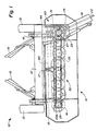
- the disc cutterbar 30 is provided with an elongated, transversely-extending transmission casing 32 having an upper portion 34, above which are rotatably operable individual disc cutters 40, 50, and a separable lower portion 33.
- the transmission casing 32 is formed with a hollow cavity 35 within which a drive transmission mechanism 20 is operably positioned.
- the transmission casing 32 is also provided with semicircular guard members 37, 37a projecting forwardly therefrom beneath the path of rotation of the respective disc cutters 40, 50 and a skid shoe 38 extending beneath the transmission casing 32 and attached to the respective guard members 37, 37a and the rear of the lower portion 33 of the transmission casing 32 to provide a structure for engagement with the ground G.
- the upper portion 34 of the transmission casing 32 carries bearings 43, 53 for the respective disc cutters 40,50.
- the removal of the lower portion 33 from the upper portion 34 of the transmission casing 32 permits access to the drive transmission mechanism 20 which remains connected to the upper portion 34. Separation of the upper portion 34 from the lower portion 33 can be accomplished by removing fasteners 31 spaced around the periphery of the transmission casing 32 and holding the two portions 33, 34 together.
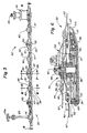
- the disc cutterbar 30 is provided with alternating generally upright disc cutters 40 and obliquely mounted disc cutters 50.
- the extreme left-hand disc cutter 51 is positioned immediately beneath the gear box 23 to receive rotational power immediately therefrom via the first output shaft 24.
- the extreme left-hand endmost disc cutter 51 and the associated first output shaft 24 are mounted obliquely to a generally vertical orientation in a manner described in greater detail below.
- the extreme right-hand disc cutter 41 is generally vertical and rotatable about an axis corresponding to the shaft 29 which delivers rotational power thereto.
- each alternate disc cutter member 50 along the transverse length of the disc cutterbar 30 is obliquely mounted, while the alternate disc cutters 40 therebetween are generally vertically oriented as is the right-hand disc cutter 41.
- Both the extreme disc cutters 41, 51 are provided with conventional divider drums to facilitate a dividing of uncut severed crop material and a rearward conveyance of the severed crop material.
- the drum on the right-hand disc cutter 41 has not been shown so as more clearly to depict the shaft 29.
- Each upright disc cutter 40 is provided with a generally vertical shaft 42 rotatably mounted within a bearing housing 43 mounted in the upper portion 34 of the transmission casing 32 to define an upright axis of rotation for the disc cutter 40.
- a rotatable disc member 45 mounted on the upper end of the shaft 42 above the upper surface of the upper portion 34 is a rotatable disc member 45 which is preferably of a generally circular shape, although other configurations would be acceptable.
- Each disc member 45 is provided with a number of pivotally mounted knives 47, preferably four knives (although more or less knives could be used) spaced equidistantly around the perimeter of the disc member 45, to severe standing crop material by impact action.
- the disc member 45 is sandwiched between an upper half 76 and lower half 77 of a split hub member 75 which is splined onto the shaft 42 to be rotatable therewith.
- a spring-loaded fastening device 46 preferably in the form of a Belleville washer and nut assembly, clamps the disc member 45 between the two halves 76, 77 of the hub 75 with an adjustable frictional clamping force. Should the disc member 45 encounter an object restricting its rotation, the disc member 45 is able to rotate relative to the hub member 75 to minimize damage to the remaining components of the disc cutterbar 30.
- a sheave 48 is affixed to the lower end of the shaft 42 within the cavity 35 of the transmission casing 32 so as to be rotatable therewithin. A shown in Fig. 6, the sheave 48 rotates in a plane substantially parallel to the upper surface 34 of the transmission casing 32.
- the construction of the oblique disc cutters 50 is substantially similar to that described above with respect to the upright disc cutters 40.
- the oblique disc cutters 50 are provided with a shaft 52 rotatably supported within a bearing housing 53 affixed to the upper surface 34 the transmission casing 32. Unlike the upright shaft 42, the top of the shaft 52 is tipped forwardly so as to define an axis of rotation for the oblique disc cutter 50 at an angle inclined to vertical.
- a disc member 55 is clamped in a split hub member 75 splined onto the top of the shaft 52 to be rotatable therewith and is frictionally held therein by a removable spring-loaded fastening device 56.
- Knives 57 are pivotally connected to the disc member 55 for rotation therewith about a plane perpendicular to the axis of rotation defined by the shaft 52. Accordingly, one skilled in the art will readily see that the path of travel of the knives 57 is in a plane tilted with respect to the plane of the path of rotation of the knives 47.
- a sheave 58 is affixed to the lower end of the shaft 52 so as to be rotatable within the cavity 35 in a plane generally parallel to the path of rotation of the knives 57.
- the shafts 52 are not only obliquely tipped relative to the axis of the shafts 42, the shafts 52 are positioned forwardly relative to the shafts 42, i.e. a line interconnecting all of the shafts 52 is located forwardly of a line interconnecting all of the shafts 42.
- This configuration places the forwardmost periphery of the rotating knives 47. Consequently, the semi-circular guards 37a corresponding to the oblique disc cutter 50 are somewhat larger and extend forwardly of the semicircular guards 37 corresponding to the upright disc cutters 40.
- the plane of the path of rotation of the knives 47 intersects the plane of the path of rotation of the knives 57 at a point substantially coincidental with the forward periphery of the path of rotation of the knives 57.
- the upper surface 34 of the transmission casing 32 is provided with a raised portion 36 immediately rearwardly of each shaft 52 to provide clearance for the angularly disposed sheave 58 within the cavity 35 of the transmission casing 32.
- the spatial interference encountered between the transmission casing 32 and the forward portion of the sheaves 58 can be accommodated by a corresponding bubble 39 formed in the transmission casing 32 immediately forwardly of each respective sheave 58.
- the path of rotation 49 of the knives 47 overlaps the adjacent path of rotation 59 of the knives 57 so as to form an overlap area 62 therebetween.
- Figs. 8 and 9 reflect three of the possible interfering positions between knives 47 and 57 within the overlap area 62, e.g. at the respective forward and rearward ends of the overlap area 62 and at the middle thereof.
- the plane of the path of rotation 59 is spaced vertically above the plane of the path of rotation 49 at all locations throughout the overlap area 62. Accordingly, unless the knives 47, 57 are damaged so as to be bent out of their intended path of rotation 49, 59, there will be no interference between knives of adjacent discs even when knives from both adjacent discs are within the overlap area 62 simultaneously. Consequently, a disc cutterbar 30 constructed as described above has no necessity for timing the rotation of adjacent disc cutters.
- a tensioning mechanism 65 includes a first arm 66 positioned above the upper surface of the transmission casing 32 and biased by a spring 67 anchored to the transmission casing 32.
- a second arm 68 positioned within the cavity 35 below the upper surface 34 to be movable with the first arm 66 carries a tensioning sheave 69 engaged with the V-belt 60 to provide appropriate tension thereto as exerted by the biasing spring 67.
- the forward portions of the sheaves 58 are located in substantially the same plane defined by the generally horizontal sheaves 48.
- V-belt 60 Since the V-belt 60 is in engagement with the sheaves 58 along this forward portion thereof and with the sheaves 48, the V-belt 60 is substantially operable within a fixed plane corresponding to the sheaves 48 so as to minimize vertical flexing thereof, which is turn maximizes operational life.
- the disc cutterbar 30 has eight disc cutters spaced along the transverse width thereof and is provided with two V-belts 60a, 60b, each providing driving power to half of the disc cutters 40. 50.
- the first group 71 of disc cutters 40, 50 corresponding to the left-hand half of the disc cutterbar 30, is rotatably driven from the left-hand disc cutter 51 via the first output shaft 24 directly providing rotational power to the sheave 58 corresponding thereto.
- the endless V-belt 60a is entrained around the idler sheaves 72, a tensioning sheave 69 and the drive sheaves 48, 58 corresponding to the first four disc cutters 40, 50.
- the rotation of the first V-belt 60a is clockwise as depicted in the plan view of Fig. 4 so as to rotate the first four disc cutters 40, 50 inwardly toward the centre of the disc cutterbar 30.
- the second group 73 of disc cutters 40, 50 correspond to the right-hand half of the disc cutterbar 30 and are driven directly by the shaft 29 which in turn is operably driven by the power transfer belt 28 transferring power from the second output shaft 26.
- the second V-belt 60b is entrained around corresponding idler sheaves 72, a second tensioning sheave 69 and the drive sheaves 48, 58 corresponding to the four disc cutters on the right-hand side of the disc cutterbar 30 to transfer rotational power from the drive sheave 48 corresponding to the extreme right-hand disc cutter 41.
- the direction of rotation of the second V-belt 60b is counter-clockwise as depicted in the plan view of Figs. 4 and 5 so as to rotate the four disc cutters 40, 50 in the second group 73 inwardly toward the centre of the disc cutterbar 30.
- the inward direction of rotation of the two groups of disc cutters 71 and 73 directs the flow of severed crop material inwardly towards the centre of the disc cutterbar 30 into a conditioning mechanism 80 supported by the frame 12 immediately rearwardly of the disc cutterbar 30, as best seen in Figs. 1 and 2.
- the conditioning mechanism 80 is preferably in the form of a pair of counter-rotating intermeshed conditioning rolls 82 of conventional design positioned to receive severed crop material directly from the disc cutterbar 30.
- the discharge of conditioned crop material from the conditioning mechanism 80 passes into the windrow shields 19 for the convergence thereof into a consolidated windrow on the ground immediately rearwardly of the machine 10.
- Rotational power to the conditioning rolls 82 is provided from a gear set 84 receiving rotational power from the gear box 23 in a generally conventional manner.
- the conditioning mechanism may be formed as a part of the header 15 so that the relationship between the conditioning mechanism 80 and the disc cutterbar 30 remains constant irrespective of the relative position of the header 15 relative to the frame 12.
- Figs. 10 and 11 an alternative embodiment of the drive mechanism for the disc cutterbar 30 can best be seen.
- the V-belt 60 is replaced with a double sided, toothed timing belt 90.
- the timing belt 90 is provided with teeth 92 having a configuration corresponding to indentations 93 on the toothed drive sprockets 88 and on the toothed idler sprockets 89 to provide a positive drive therebetween.
- a toothed timing belt 90 provides a means more to positively drive the disc cutters 40, 50 and thereby time the rotation between respective adjacent disc cutters 40, 50 without encountering the manufacturing and operational expenses of gear driven disc cutterbars.
- the drive sprockets 88 could still slip relative to the timing belt 90 without causing major damage to the cutterbar 30 if the rotation thereof were impeded.
- Timing belt 90 permits the rotation of the adjacent disc cutters 40, 50 to have differing configurations, as seen in comparison between Fig. 10 and Fig. 11.
- Entraining the timing belt 90 around the forward portion of one drive sprocket 88 and around the rearward portion of the adjacent drive sprocket 88 permits the adjacent disc cutters to be driven in opposing directions as indicated by arrows 96 in Fig. 11.
- the varying of the rotational configuration of the individual disc cutters 40, 50 can be accomplished whether a V-belt 60 or a timing belt 90 is utilised.
- a V-belt embodiment of the drive mechanism 20 the staggered location of adjacent disc cutters 40, 50 permits an adequate wrapping of the drive belt 60 around the respective drive sheaves 48, 58 to effect the transfer of power therebetween irrespective of whether an idler 72 is used.
- the transverse width of the conditioning mechanism 80 is less than the transverse cutting width of the disc cutterbar 30
- the utilization of a belt drive mechanism within the transmission casing 32 will provide a lower cost disc cutterbar 30 compared to gear-driven cutterbars.
- the belt driven disc cutterbar 30 will be quieter in operation than conventional gear-driven disc cutterbars. Since timing of adjacent disc cutters is not required by virtue of the vertical separation of the paths of rotation within the overlap area 62, any number of knives can be used on the respective disc cutter. The preferred number of four knives per disc cutter is believed to provide a satisfactory cutting performance without leaving strips of uncut crop material between adjacent blades; however, more or less knives per disc cutter could be used.
- the belt-driven disc cutterbar will be less susceptible to damage because of the ability of the drive sheaves to slip relative to the engaged drive belt with respect to each individual disc cutter should rotation of that disc cutter become impeded, such as by impact with a substantial object.
- the ability of the disc member 45, 55 to rotate relative to the hub member 75 mounting the respective disc member 45, 55 to the corresponding shaft 42, 52 also provides a secondary capability for the disc cutterbar 30 to escape extensive damage upon impact with a substantial object.
Landscapes
- Life Sciences & Earth Sciences (AREA)
- Environmental Sciences (AREA)
- Harvester Elements (AREA)
Applications Claiming Priority (2)
| Application Number | Priority Date | Filing Date | Title |
|---|---|---|---|
| US07/240,863 US4888939A (en) | 1988-09-02 | 1988-09-02 | Belt driven disc cutterbar |
| US240863 | 1988-09-02 |
Publications (1)
| Publication Number | Publication Date |
|---|---|
| EP0357313A1 true EP0357313A1 (de) | 1990-03-07 |
Family
ID=22908250
Family Applications (1)
| Application Number | Title | Priority Date | Filing Date |
|---|---|---|---|
| EP89308467A Ceased EP0357313A1 (de) | 1988-09-02 | 1989-08-21 | Scheibenmähbalken mit Riemenantrieb |
Country Status (2)
| Country | Link |
|---|---|
| US (1) | US4888939A (de) |
| EP (1) | EP0357313A1 (de) |
Cited By (1)
| Publication number | Priority date | Publication date | Assignee | Title |
|---|---|---|---|---|
| FR2742299A1 (fr) * | 1995-12-02 | 1997-06-20 | Grenzebach Hans | Faucheuse a disques |
Families Citing this family (12)
| Publication number | Priority date | Publication date | Assignee | Title |
|---|---|---|---|---|
| US6250056B1 (en) * | 1998-01-05 | 2001-06-26 | F & T Spagnolo Pty Ltd. | Rotary blade pruning machine |
| US6035619A (en) * | 1998-02-02 | 2000-03-14 | Gehl Company | Combination gearbox drive system for a disc mower conditioner |
| TWI224493B (en) * | 1999-04-05 | 2004-12-01 | Marujun Juko Kk | Rotary plant mowing apparatus |
| USD458279S1 (en) | 2001-05-31 | 2002-06-04 | New Holland North America, Inc. | Knife for an agricultural cutterhead |
| US6581362B2 (en) * | 2001-06-19 | 2003-06-24 | Deere & Company | Crop converging arrangement for mower-conditioner equipped with a rotary disc cutter bar |
| US7111682B2 (en) * | 2003-07-21 | 2006-09-26 | Mark Kevin Blaisdell | Method and apparatus for gas displacement well systems |
| FR3052016B1 (fr) * | 2016-06-01 | 2018-06-15 | Kuhn S.A. | Faucheuse a barre de coupe a disques rotatifs a couteaux |
| USD795307S1 (en) * | 2017-04-27 | 2017-08-22 | Joseph W. Stout | Limb and branch trimming apparatus |
| DE102019002828B3 (de) * | 2019-04-18 | 2020-06-04 | Maschinenfabrik Bernard Krone GmbH & Co. KG | Mähmaschine |
| CN115889891B (zh) * | 2022-12-15 | 2023-06-20 | 广东福临门世家智能家居有限公司 | 一种低噪音铝型材切割装置及切割方法 |
| CN116773237B (zh) * | 2023-06-14 | 2026-04-07 | 中国农业大学 | 一种圆盘式切割器试验装置与切割参数调节方法 |
| CN119187792B (zh) * | 2024-10-09 | 2025-06-03 | 苏州纳希微半导体有限公司 | 一种芯片测试工装等离子切割设备及方法 |
Citations (5)
| Publication number | Priority date | Publication date | Assignee | Title |
|---|---|---|---|---|
| DE1582353A1 (de) * | 1967-10-07 | 1970-08-13 | Koedel & Boehm Gmbh | Kreiselmaehwerk |
| DE2746960A1 (de) * | 1977-07-22 | 1979-02-01 | Kuhn Sa | Maehaufbereiter |
| DE3304199A1 (de) * | 1982-02-12 | 1983-08-25 | Osakeyhtiö Wärtsilä Ab, 00101 Helsinki | Maehvorrichtung |
| US4730445A (en) * | 1985-06-17 | 1988-03-15 | Kuhn, S.A. | Rotary mower |
| EP0267659A2 (de) * | 1986-11-12 | 1988-05-18 | C. van der Lely N.V. | Mähmaschine |
Family Cites Families (11)
| Publication number | Priority date | Publication date | Assignee | Title |
|---|---|---|---|---|
| US3116583A (en) * | 1960-07-05 | 1964-01-07 | Steven J Mason | Gang rotary mower |
| US3138911A (en) * | 1962-07-17 | 1964-06-30 | James Herbert Pounds | Hedge trimmer |
| US3457714A (en) * | 1966-09-14 | 1969-07-29 | Simplicity Mfg Co Inc | Mowing apparatus with rotary cutters |
| NL7513926A (nl) * | 1975-11-28 | 1977-06-01 | Multinorm Bv | Maaiinrichting. |
| US4160356A (en) * | 1978-02-06 | 1979-07-10 | Mathews B C | Drive for mower |
| NL7806654A (nl) * | 1978-06-20 | 1979-12-27 | Multinorm Bv | Maaiinrichting. |
| US4302922A (en) * | 1980-07-07 | 1981-12-01 | Orange Enterprises, Inc. | Pruning boom |
| NL8103411A (nl) * | 1981-07-17 | 1983-02-16 | Multinorm Bv | Maaier. |
| NL8400818A (nl) * | 1984-03-15 | 1985-10-01 | Lely Nv C Van Der | Maaimachine. |
| FR2570248B1 (fr) * | 1984-09-19 | 1990-06-29 | Kuhn Sa | Faucheuse rotative |
| US4653253A (en) * | 1986-03-31 | 1987-03-31 | New Holland Inc. | Self-cleaning rotor assembly |
-
1988
- 1988-09-02 US US07/240,863 patent/US4888939A/en not_active Expired - Lifetime
-
1989
- 1989-08-21 EP EP89308467A patent/EP0357313A1/de not_active Ceased
Patent Citations (5)
| Publication number | Priority date | Publication date | Assignee | Title |
|---|---|---|---|---|
| DE1582353A1 (de) * | 1967-10-07 | 1970-08-13 | Koedel & Boehm Gmbh | Kreiselmaehwerk |
| DE2746960A1 (de) * | 1977-07-22 | 1979-02-01 | Kuhn Sa | Maehaufbereiter |
| DE3304199A1 (de) * | 1982-02-12 | 1983-08-25 | Osakeyhtiö Wärtsilä Ab, 00101 Helsinki | Maehvorrichtung |
| US4730445A (en) * | 1985-06-17 | 1988-03-15 | Kuhn, S.A. | Rotary mower |
| EP0267659A2 (de) * | 1986-11-12 | 1988-05-18 | C. van der Lely N.V. | Mähmaschine |
Cited By (1)
| Publication number | Priority date | Publication date | Assignee | Title |
|---|---|---|---|---|
| FR2742299A1 (fr) * | 1995-12-02 | 1997-06-20 | Grenzebach Hans | Faucheuse a disques |
Also Published As
| Publication number | Publication date |
|---|---|
| US4888939A (en) | 1989-12-26 |
Similar Documents
| Publication | Publication Date | Title |
|---|---|---|
| EP0357313A1 (de) | Scheibenmähbalken mit Riemenantrieb | |
| US6247296B1 (en) | Drive arrangement for the crop conveying and/or processing mechanism of a harvesting machine | |
| US5937624A (en) | Disc cutterbar drive module with integral knife stop | |
| US5330114A (en) | Shredder attachment for combine corn head | |
| US4739609A (en) | Device for mowing and conditioning hay | |
| US4065912A (en) | Cane cutting apparatus | |
| EP2108243B1 (de) | Auf der Schneideeinheit eines Rollenrasenmähers montierbarer Hilfsantrieb | |
| US4244163A (en) | Device for reducing the width of windrows formed by a mower | |
| CA2608789A1 (en) | Mower conditioner having auger flights positioned over a cutter bat to effect clearing thereof | |
| CA1125035A (en) | Crop harvesting machine | |
| EP2108241B1 (de) | Auf der Schneideeinheit eines Rollenrasenmähers montierbarer Hilfsantrieb | |
| US4887416A (en) | Timing belt for disc cutterbars | |
| US4890445A (en) | Disc cutter construction | |
| US3543490A (en) | Flexible rotary mower | |
| US4078734A (en) | Drive arrangement for field choppers | |
| EP0357312A1 (de) | Geteilter Mähbalken-Antriebsmechanismus | |
| US4337612A (en) | Row crop unit | |
| US4397134A (en) | Row crop attachment with sweeper chain | |
| DE3304199C2 (de) | ||
| US3780505A (en) | Crop conditioner drive | |
| US4142349A (en) | Disk type mower | |
| US4251981A (en) | Mowing machines | |
| KR200253187Y1 (ko) | 농기계용 예취기 | |
| EP1719401B1 (de) | Mähwerkgehäuse | |
| US3106053A (en) | Endless chain cutters for harvesters, mowers and other agricultural implements |
Legal Events
| Date | Code | Title | Description |
|---|---|---|---|
| PUAI | Public reference made under article 153(3) epc to a published international application that has entered the european phase |
Free format text: ORIGINAL CODE: 0009012 |
|
| AK | Designated contracting states |
Kind code of ref document: A1 Designated state(s): DE FR GB |
|
| 17P | Request for examination filed |
Effective date: 19900924 |
|
| 17Q | First examination report despatched |
Effective date: 19911016 |
|
| RAP1 | Party data changed (applicant data changed or rights of an application transferred) |
Owner name: NEW HOLLAND BELGIUM N.V. |
|
| STAA | Information on the status of an ep patent application or granted ep patent |
Free format text: STATUS: THE APPLICATION HAS BEEN REFUSED |
|
| 18R | Application refused |
Effective date: 19940106 |