EP0357411A2 - Gesteuerter Induktanzregler zur Kommutierung einer Leistungsversorgung - Google Patents
Gesteuerter Induktanzregler zur Kommutierung einer Leistungsversorgung Download PDFInfo
- Publication number
- EP0357411A2 EP0357411A2 EP89308799A EP89308799A EP0357411A2 EP 0357411 A2 EP0357411 A2 EP 0357411A2 EP 89308799 A EP89308799 A EP 89308799A EP 89308799 A EP89308799 A EP 89308799A EP 0357411 A2 EP0357411 A2 EP 0357411A2
- Authority
- EP
- European Patent Office
- Prior art keywords
- current
- core
- control
- magnetic amplifier
- winding
- Prior art date
- Legal status (The legal status is an assumption and is not a legal conclusion. Google has not performed a legal analysis and makes no representation as to the accuracy of the status listed.)
- Withdrawn
Links
- 239000011162 core material Substances 0.000 claims abstract description 90
- 230000005291 magnetic effect Effects 0.000 claims abstract description 43
- 229910000859 α-Fe Inorganic materials 0.000 claims abstract description 19
- 238000004804 winding Methods 0.000 claims description 84
- 238000001914 filtration Methods 0.000 claims 1
- PXHVJJICTQNCMI-UHFFFAOYSA-N Nickel Chemical group [Ni] PXHVJJICTQNCMI-UHFFFAOYSA-N 0.000 abstract description 14
- 230000005389 magnetism Effects 0.000 abstract description 3
- 230000004907 flux Effects 0.000 description 19
- 239000000463 material Substances 0.000 description 12
- 229910052759 nickel Inorganic materials 0.000 description 6
- 230000003321 amplification Effects 0.000 description 4
- 230000000903 blocking effect Effects 0.000 description 4
- 230000000670 limiting effect Effects 0.000 description 4
- 238000003199 nucleic acid amplification method Methods 0.000 description 4
- 230000007423 decrease Effects 0.000 description 3
- 230000001965 increasing effect Effects 0.000 description 3
- 238000000034 method Methods 0.000 description 3
- 230000035699 permeability Effects 0.000 description 3
- 208000002447 Macrophagic myofasciitis Diseases 0.000 description 2
- 230000033228 biological regulation Effects 0.000 description 2
- 238000010586 diagram Methods 0.000 description 2
- 229920006395 saturated elastomer Polymers 0.000 description 2
- 229910001035 Soft ferrite Inorganic materials 0.000 description 1
- 230000006978 adaptation Effects 0.000 description 1
- 230000008901 benefit Effects 0.000 description 1
- 239000003990 capacitor Substances 0.000 description 1
- 230000008859 change Effects 0.000 description 1
- 238000010276 construction Methods 0.000 description 1
- 238000013016 damping Methods 0.000 description 1
- 230000001934 delay Effects 0.000 description 1
- 230000009977 dual effect Effects 0.000 description 1
- 238000010438 heat treatment Methods 0.000 description 1
- 230000001939 inductive effect Effects 0.000 description 1
- 238000009413 insulation Methods 0.000 description 1
- 230000005415 magnetization Effects 0.000 description 1
- 238000012986 modification Methods 0.000 description 1
- 230000004048 modification Effects 0.000 description 1
- 230000000135 prohibitive effect Effects 0.000 description 1
- 238000009738 saturating Methods 0.000 description 1
Images



Classifications
-
- H—ELECTRICITY
- H03—ELECTRONIC CIRCUITRY
- H03F—AMPLIFIERS
- H03F9/00—Magnetic amplifiers
- H03F9/02—Magnetic amplifiers current-controlled, i.e. the load current flowing in both directions through a main coil
-
- H—ELECTRICITY
- H02—GENERATION; CONVERSION OR DISTRIBUTION OF ELECTRIC POWER
- H02M—APPARATUS FOR CONVERSION BETWEEN AC AND AC, BETWEEN AC AND DC, OR BETWEEN DC AND DC, AND FOR USE WITH MAINS OR SIMILAR POWER SUPPLY SYSTEMS; CONVERSION OF DC OR AC INPUT POWER INTO SURGE OUTPUT POWER; CONTROL OR REGULATION THEREOF
- H02M7/00—Conversion of AC power input into DC power output; Conversion of DC power input into AC power output
- H02M7/02—Conversion of AC power input into DC power output without possibility of reversal
- H02M7/04—Conversion of AC power input into DC power output without possibility of reversal by static converters
- H02M7/06—Conversion of AC power input into DC power output without possibility of reversal by static converters using discharge tubes without control electrode or semiconductor devices without control electrode
- H02M7/066—Conversion of AC power input into DC power output without possibility of reversal by static converters using discharge tubes without control electrode or semiconductor devices without control electrode particular circuits having a special characteristic
-
- H—ELECTRICITY
- H03—ELECTRONIC CIRCUITRY
- H03K—PULSE TECHNIQUE
- H03K17/00—Electronic switching or gating, i.e. not by contact-making and –breaking
- H03K17/51—Electronic switching or gating, i.e. not by contact-making and –breaking characterised by the components used
- H03K17/80—Electronic switching or gating, i.e. not by contact-making and –breaking characterised by the components used using non-linear magnetic devices; using non-linear dielectric devices
-
- H—ELECTRICITY
- H01—ELECTRIC ELEMENTS
- H01F—MAGNETS; INDUCTANCES; TRANSFORMERS; SELECTION OF MATERIALS FOR THEIR MAGNETIC PROPERTIES
- H01F29/00—Variable transformers or inductances not covered by group H01F21/00
- H01F29/14—Variable transformers or inductances not covered by group H01F21/00 with variable magnetic bias
Definitions
- the present invention relates to switching power supplies and in particular to regulation circuits using a saturable inductive element having very low permeability after saturation and very low remanence to operate as a controlled-inductance switch.
- mag amps Magnetic amplifiers, or mag amps, have a long history in various applications dating back to the early 1900's. This ver severelysatile electronic element continues to be used in many modern switching power supplies.
- a mag amp is a coil of wire wound on a core having relatively square or rectangular B-H (flux density-magnetizing force) characteristics. The coil then has two operating states. In the first, when the core is unsaturated, the coil acts as a high inductance blocking current flow and supports a large voltage. Once the core saturates, the impedance of the coil drops to near zero, allowing current to flow with a minimum voltage drop. The mag amp thus operates as a switch controlling current flow through the coil with low losses, capable of operating at a high switching speed.
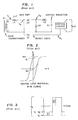
- mag amp An example of a simple prior art mag amp is shown in Fig. 1.
- This mag amp is constructed as a portion of a post-regulator circuit in which only the secondary of transformer T1 is shown.
- the primary of transformer T1 is driven with a square wave from a standard switching power supply with a switching speed of typically 20-70 kHZ.
- the core material of mag amp L1 uses materials with a square magnetic hysteresis loop of the type shown in Fig. 2 such that the remanent flux density is a high percentage of the saturation flux density. This ensures that the minimum delay between applying a voltage across the mag amp and when the mag amp goes into saturation is as small as possible when no reset is applied.
- mag amp L1 acts as a pulse width modulator (PWM) going from high to low impedance when mag amp L1 saturates.
- PWM pulse width modulator
- the time the mag amp L1 takes to saturate is controlled by allowing current to flow through diode D1 when the transformer T1 reverses polarity during a switching cycle to reset the magnetism of mag amp L1.
- the post-regulator circuit shown in Fig. 1 is a buck regulator which requires an output LC filter to convert the pulse width modulated output to DC.
- the mag amp does not require a DC input, however, since it operates directly off the secondary winding of the power transformer receiving a rectangular or pulse DC waveform. In operation, the mag amp delays the leading edge ( see area B of Fig. 3) of the power pulse from power transformer T1 until the remainder of the pulse width is narrowed to maintain the correct output voltage level desired on the output of the post-regulator circuit.
- the post-regulator lowers the output voltage and maintains it at a steady voltage independent of the load current.
- a control circuit can be used to provide the reset voltage necessary to reset mag amp L1 at the appropriate time depending upon the desired output voltage.
- control circuit part No. UC1838 available from Unitrode Corporation is commonly used.
- Fig. 3 the same volt-microseconds induced in the core material in area A during reset is equal to the volt-microseconds in area B which is required to overcome the induced magentism before the mag amp will switch on.
- the B-H operating curve of the squared loop material used for magnetic amplifier L1 is shown in prior art Fig. 2.
- the time to saturation of the core depends upon the core material, area of the core, applied voltage, and number of turns around the loop in mag amp L1.
- the control circuit can then adjust the pulse width during which the mag amp is saturated to keep the output voltage constant under varying load conditions.
- Using square loop material ensures a simple device with one winding which carries both power current and reset control current independently at appropriate times.
- All square loop materials exhibit the characteristic where B r (the remanent flux density) is typically 90% of Bm (the maximum saturation flux density).
- B r the remanent flux density
- Bm the maximum saturation flux density
- the square-loop characteristics for a ferrite core material shown in Fig. 2 are B m approximately equal to 4000 gauss and B r approximately equal to 3600 gauss.
- the square-loop characteristics for a ferrite (nickel-based) core material shown in Fig. 2 are B m approximately equal to 7000 gauss and B r approximately equal to 6300 gauss.
- Ferrite square loop material is known in the prior art and is less expensive (typically $0.40 per core) compared to the nickel-based cores described above. These cores are very lossy at high frequency, the losses being proportional to the area within the square loop shown in Fig. 2. Ferrite square loop characteristics also tend to vary with operating temperature and tend to crack under high temperature operating conditions (related to the high losses and internal heating).
- the present invention solves the aforementioned problems in the prior art and other problems that will be recognized by those skilled in the art upon reading this specification. and understanding the present invention.
- the present invention comprises a regulator circuit employing a magnetic amplifier constructed using non-nickel core material, such as ferrite, having a very narrow B-H operating curve (flat-loop) in which the remenance (residual magnetism B r ) is below 1000 gauss.
- the present invention operates as a controlled inductance so that saturation is approached slowly and allows operations at or above 100 kHz with minimal losses and minimal EMI or RF noise.
- the present invention accomplishes current limiting without external current limiting circuitry since the present invention only allows the proportional amount of current out that the control winding current is placed in.
- the present invention is designed to be connected to the secondary of the power output transformer of a switching power supply.
- the present invention operates as a post-regulator with a ferrite-like core material having a narrow B-H characteristic curve.
- the mag amp is placed in series with the power output transformer and rectifying diodes.
- the output of the mag amp through a rectifying diode is then placed into an LC filter circuit to provide a smooth stabilized voltage output regardless of the load current.
- a control circuit is provided as a secondary winding on the magnetic amplifier which provides reset current on the mag amp.
- Fig. 4 shows a typical flat-loop B-H curve of a core material such as ferrite used in the magnetic amplifier of the preferred embodiments of the present invention.
- the BH loop should indicate very low permeability after saturation and in a single-ended version of the preferred embodiment of the present invention, the remanence should be as low as possible (below 1000 gauss) to ensure the maximum delta B or switching time from B r to B m .
- materials other than ferrite may be used for the magnetic amplifier as long as the remanence of the cores is maintained below 1000 gauss.
- the square loop characteristics for a ferrite core material shown in Fig. 4 are B m approximately equal to 4000 gauss and B r approximately equal to 700 gauss.
- the remanent flux density B r is typically 17% of the maximum saturation flux density B m .
- Fig. 5 shows a magnetic amplifier using the ferrite core material described by the B-H characteristics of Fig. 4.
- a secondary or control winding is added to the ferrite core to help the core saturate and to prevent full automatic reset to remanence in order to vary the pulse width of the current allowed through the mag amp.
- the circuit of Fig. 5 is connected to a 20-volt, 6-amp output transformer winding 501 of a 400-watt switching power supply (not shown) available from the assignee of the present invention.
- the mag amp is constructed using a 35mm "E" core with both the main winding and the control winding on the center leg.
- the material was constructed of a nominal ferrite power material, part No. 3E2E available from FerroxCube, a branch of North American Phillips costing approximate $0.40 a piece in quantity.
- mag amp To achieve full current blocking (never saturating), the mag amp must hold off the full volt seconds of the secondary of the transformer winding.
- a 20-volt peak square wave is produced by transformer 501.
- the voltage that the main coil of mag amp 502 must hold off is a 20-volt peak for 6 microseconds.
- the flux excursion allowed between remanance and saturation is approximately 300 millitesla. In order to stay out of saturation, the present invention described in Fig. 5 allowed 250 milliteslas.
- the control winding was constructed of 40 turns of 23-gauge wire such that the peak voltage due to the turns ratio was approximately 160 volts.
- a 400-volt 8-amp epitaxial rectifier 504 is placed in series with a 1-kilohm 50-watt potentiometer to control the reset current through the control winding of mag amp 502.
- the dots on the mag amp winding shown in Fig. 5 show that the current in the control winding flows in the same sense as the main power current when rectifier 505 is forward biased.
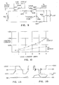
- the voltage and current waveforms for the circuit of Fig. 5 are shown in Fig. 6.
- the approximately 20-volt peak square wave of transformer 501 is shown in the upper portion of Fig. 6 as the transformer output voltage.
- the current through the mag amp main winding is shown on the second line of Fig. 6 along with the control current through the control winding of mag amp 502 on the third line of Fig. 6.
- the mag amp 502 is in a high impedance state and therefore magnetizing current only flows as the core is being magnetized up the steep part of the B-H curve. As the magnetization increases further, saturation is approached as the effective permeability decreases.
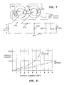
- the second preferred embodiment of the present invention shown in Fig. 7 operates to eliminate the problem of high induced voltage in the control winding due to the turns ratio.
- the two cores shown in Fig. 7 are ferrite core part No. 42908-TC-J available from Magnetics, Inc., a division of Spang & Co. of Butler, Pennsylvania.
- the control windings are wound such that the voltage induced from one core is equal and opposite to the voltage induced by the other.
- An external control power supply is used to drive current around the control windings of the mag amp and the voltage required was that necessary to overcome the resistance of the wire of the control windings.
- ferrite core 602 receives nine turns of the main winding in common with ferrite core 603.
- Control windings of cores 602 and 603 are constructed of sixty turns on each core placed in series with the control circuit.
- the control circuit produces a control voltage through the windings that may be proportional to the varying load conditions on the output of the circuit of Fig. 7.
- the main power winding turns were chosen so that with no control current flowing through the control windings, the cores do not saturate.
- FIG. 8 the current amplification of the circuit of Fig. 7 is graphically shown. For a 5-volt post-regulator output, current amplification of better than 10:1 is available.
- FIG. 9 A two-toroid mag amp was constructed with one core 901 being smaller than the other core 902.
- the direction of the windings is shown with dots in Fig. 9, and the physical construction is similar to that of Fig. 7 except for the area of the toroids. Seven turns of the main winding are wound in common between the two toroids, and the control win dings on separate toroids are placed in series with a control circuit to produce the control winding voltage.
- a snubber circuit is included on the smaller toroid constructed using an RC damping circuit comprised of a 7.5-kilohm resistor in series with a 0.0012 microfarad capacitor placed in parallel with the control winding on the smaller toroid.
- a snubber circuit is included on the smaller toroid constructed using an RC damping circuit comprised of a 7.5-kilohm resistor in series with a 0.0012 microfarad capacitor placed in parallel with the control winding on the smaller toroid.
- the result is similar to that used with equal area cores with approximately ten percent greater control range.
- the results are shown in Fig. 10 with a current amplification for a 5-volt output of approximately 13:1.
- Figs. 11a and 11b Voltage waveforms taken across the main control winding of the third preferred embodiment of the present invention shown in Fig. 9 are shown in Figs. 11a and 11b.
- the core With zero control current, the core will not saturate at the selected frequency of approximately 100 kHz, as shown in Fig. 11a where magnetizing current only is flowing.
- Zero control current thus effectively blocks all voltage output on the post-regulator circuit since all of the applied voltage from the transformer is dropped across the mag amp. Placing a voltage across the control winding produces an output voltage on the post-regulator circuit proportional to the amount of current induced in the control windings of the toroids.
- pulse width modulation is taking place at the operating frequency of the switching power supply.
- the mag amp now supports the applied voltage for approximately a quarter of the total time, and goes quickly into saturation.
- the transformer voltage reverses, the voltage across the mag amp reverses and the current falls back to zero at the same slope but reversed sign at which it rose.
- the dI/dt is limited by the choke 507.
- the graphs of Fig. 11a and 11b demonstrate the full control range from blocking (magnetizing current flows only) to maximum output. Beyond a control current of 0.75 amps, the control becomes non-linear and doubling the control current only gives ten percent more output current (at the same voltage).
- the current in the control winding gives rise to a magneto motive force (MMF) which is shown by the arrows on the toroids of Fig. 7.
- MMF magneto motive force
- the direction of the MMF caused by control winding in one core opposes the MMF caused by the main winding, while in the other core the direction of the MMF caused by the control winding adds to the MMF caused by the main winding.
- the inductance during the current rise and fall times decreases as the current in the control winding increases.
- the smaller core 901 of Fig. 9 (in which the two MMFs add) is moved quickly toward saturation and thus ceases to support the voltage across its control winding.
- the control winding on core 901 is connected to the other control winding on core 902, the voltage across it is fixed by the former.
- the main winding current increases, its flux balances the flux due to the control current in the core with the opposing MMFs, at which point the inductance goes toward zero.
- the opposing flux in core 902 reduces, allowing the balancing from main winding to occur earlier.
- the current ramps up faster to a level when it is saturated.
- core 902 acts as a current transformer as the core 901 goes into saturation.
- Figs. 5, 7 and 9 demonstrate that a high-frequency, low-loss mag amp is feasible using flat-loop material.
- This design overcomes the potential frequency limits of the square-loop materials because the aforementioned embodiments incorporate soft ferrite materials and the like which have superior high-frequency performance.
- Fig. 7 the concept of using opposing control windings to cancel the induced voltages in the control circuit simplifies the design since the control circuit does not need to be high-voltage isolated or protected.
- Fig. 12 the concepts of Figs. 7 and 9 are incorporated by substituting an E core 701 for the individual two toroids in which the power winding is wound around the center leg.
- the mag amp changes state when one of the outer legs saturates.
- any voltage appearing across the transformer 501 will induce a voltage (determined by the turns ratio N c /N p ) across the control windings (Va and V b ).
- N c /N p the voltage induced across that winding collapses, and because of the conection of the two control windings, the other control winding has the same loss of voltage.
- a corresponding drop in voltage across the power winding N p removes the "blocking condition" and current can flow through N p up to a maximum value determined by the control winding current and the turns ratio N c /N p .
- the device has changed state from a voltage transformer to a current transformer, the current of which is determined by the control current. This state will remain until the rest of the device reaches saturation, at which time all controlling influence will be lost.
- FIG. 13 An alternate embodiment to that shown in Fig. 12 is shown in Fig. 13, where the power windings are on the outer legs and the control winding on the center pole. No AC component is induced in the control winding from the power windings since any flux from one power winding which tries to enter the center pole is opposed by the flux from the other power winding (see positions A and B on Fig. 13).
- the flux from the control winding adds to the power flux in one leg, and opposes the power flux in the other leg in the same way as the previous embodiment, and the manner of control is similar.
- the main advantage with the method of Fig. 13 is that the control winding sees no AC flux, whereas in the Fig.
- the AC flux which one half of the control winding sees includes voltages which are balanced by the voltages in the other half by the method of connection. However, at the junction of the two halves of the control winding high voltages (200V-600V) are observed. so suitable insulation has to be provided.
- Fig. 14 shows a post regulator circuit which employs a preferred embodiment of the present invention.
- Inductor L3 corresponds to the flat-loop ferrite double E core configuration shown in Fig. 13. Two opposing nine-turn windings for the power windings are wound on the outer legs of the core with a 300-turn control winding wound on the center leg of the core controlled by a magnetic amplifier controller chip and associated circuitry.
- the magnetic amplifier L3 is connected according to the teachings of the present invention to control a +24 volt DC post regulator circuit employing an LC filter comprised of inductor L4 and capictors C16, C18, C68.
- the post regulator circuit derives its pulse power from the secondary of transformer T4, the primary of which (not shown) is attached to the output of a switching power supply.
- the magnetic amplifier controller integrated circuit UC3838 (available from Unitrode) contains all of the circuitry necessary to generate and amplify a low level analog error signal which is used to produce the reset current to enable a magnetic amplifier to regulate a power supply output.
- the integrated circuit is connected according to manufacturer specifications to receive a voltage feedback signal on pin 7 and produce the reset signal on pin 14.
- the reset signal on pin 14 is used to drive the base of transistor Q101 which in turn controls the reset voltage to the control winding of the flat-loop magnetic.amplifier L3.
- Integrated circuit UC3838 defines the amount of volt-seconds the magnetic amplifier L3 will block before switching to the conducting state.
- the integrated circuit 14 is manufactured and sold to operate on a square-loop core material for a magnetic amplifier. With the implementation shown in Fig. 14, the integrated circuit can be connected to operate on the flat loop ferrite-type core materials as described in the preferred embodiments of the present invention.
Landscapes
- Engineering & Computer Science (AREA)
- Power Engineering (AREA)
- Physics & Mathematics (AREA)
- Nonlinear Science (AREA)
- Amplifiers (AREA)
- Dc-Dc Converters (AREA)
Applications Claiming Priority (2)
| Application Number | Priority Date | Filing Date | Title |
|---|---|---|---|
| US23929588A | 1988-08-31 | 1988-08-31 | |
| US239295 | 1988-08-31 |
Publications (2)
| Publication Number | Publication Date |
|---|---|
| EP0357411A2 true EP0357411A2 (de) | 1990-03-07 |
| EP0357411A3 EP0357411A3 (de) | 1990-10-31 |
Family
ID=22901532
Family Applications (1)
| Application Number | Title | Priority Date | Filing Date |
|---|---|---|---|
| EP19890308799 Withdrawn EP0357411A3 (de) | 1988-08-31 | 1989-08-31 | Gesteuerter Induktanzregler zur Kommutierung einer Leistungsversorgung |
Country Status (1)
| Country | Link |
|---|---|
| EP (1) | EP0357411A3 (de) |
Cited By (4)
| Publication number | Priority date | Publication date | Assignee | Title |
|---|---|---|---|---|
| EP0589204A3 (de) * | 1992-09-23 | 1994-12-07 | Zeltron Spa | Verbesserung einer spannungsstabilisierten Stromversorgungsschaltung für einen Verstärkerwandler. |
| WO2007072260A1 (en) * | 2005-12-21 | 2007-06-28 | Koninklijke Philips Electronics N.V. | Device for driving a discharge lamp, and switching circuit for use in such device |
| WO2012128882A3 (en) * | 2011-02-25 | 2012-11-29 | Ut-Battelle, Llc | Power flow control using distributed saturable reactors |
| EP2798716A4 (de) * | 2011-12-09 | 2016-03-09 | Asg Superconductors S P A | Fehlerstrombegrenzer |
Family Cites Families (5)
| Publication number | Priority date | Publication date | Assignee | Title |
|---|---|---|---|---|
| GB1250935A (de) * | 1968-06-07 | 1971-10-27 | ||
| US3612988A (en) * | 1969-09-15 | 1971-10-12 | Wanlass Cravens Lamar | Flux-gated voltage regulator |
| NL7811969A (nl) * | 1978-12-08 | 1980-06-10 | Philips Nv | Schakelende voeding met meerdere uitgangen. |
| US4419723A (en) * | 1981-10-29 | 1983-12-06 | Bell Telephone Laboratories, Incorporated | Regulation of multiple-output DC-DC converters |
| DE3671553D1 (de) * | 1986-08-08 | 1990-06-28 | Ibm | Energieversorgungen mit magnetverstaerker zur spannungsregelung. |
-
1989
- 1989-08-31 EP EP19890308799 patent/EP0357411A3/de not_active Withdrawn
Cited By (5)
| Publication number | Priority date | Publication date | Assignee | Title |
|---|---|---|---|---|
| EP0589204A3 (de) * | 1992-09-23 | 1994-12-07 | Zeltron Spa | Verbesserung einer spannungsstabilisierten Stromversorgungsschaltung für einen Verstärkerwandler. |
| WO2007072260A1 (en) * | 2005-12-21 | 2007-06-28 | Koninklijke Philips Electronics N.V. | Device for driving a discharge lamp, and switching circuit for use in such device |
| WO2012128882A3 (en) * | 2011-02-25 | 2012-11-29 | Ut-Battelle, Llc | Power flow control using distributed saturable reactors |
| US9261890B2 (en) | 2011-02-25 | 2016-02-16 | Ut-Battelle, Llc | Power flow control using distributed saturable reactors |
| EP2798716A4 (de) * | 2011-12-09 | 2016-03-09 | Asg Superconductors S P A | Fehlerstrombegrenzer |
Also Published As
| Publication number | Publication date |
|---|---|
| EP0357411A3 (de) | 1990-10-31 |
Similar Documents
| Publication | Publication Date | Title |
|---|---|---|
| US4327348A (en) | Variable leakage transformer | |
| US3805094A (en) | Driving circuit for a switching transistor | |
| US5646836A (en) | Switch mode power supply using a saturable inductor to provide a pulsed current source | |
| US4199744A (en) | Magnetic core with magnetic ribbon in gap thereof | |
| US4399376A (en) | High frequency switching circuit | |
| EP1050952A1 (de) | Gleichrichtungs- und dämpfungsschaltung mit doppelendigem umrichter | |
| US5450052A (en) | Magnetically variable inductor for high power audio and radio frequency applications | |
| US4123670A (en) | Transistor switching circuit | |
| JPS62189347A (ja) | 電流の急速転送装置 | |
| EP0284615B1 (de) | Materialmagnetisierungsmethode und -vorrichtung | |
| Harada et al. | Ferroresonant converters with high-frequency drive | |
| US5249113A (en) | Dc to dc converter of the push-pull type with mosfet switches | |
| RU2129331C1 (ru) | Генератор импульсов | |
| KR0149668B1 (ko) | 유도성 부하 구동회로 및 그 방법 | |
| JPS627368A (ja) | 電源回路 | |
| US2983862A (en) | Magnetic voltage reference device | |
| US5159540A (en) | High-efficiency saturable core voltage converter | |
| WO1999009569A1 (en) | Controlled ferroresonant transformer | |
| RU2118860C1 (ru) | Трансформатор | |
| EP0616740B1 (de) | Gleichstromumrichter | |
| GB2042277A (en) | Transformer for use in a static inverter | |
| US2886658A (en) | Inductively reset carrier magnetic amplifier | |
| SU1427561A1 (ru) | Фазовращатель | |
| JPS5924627B2 (ja) | スイッチング電源 | |
| SU1190449A1 (ru) | Преобразователь посто нного напр жени |
Legal Events
| Date | Code | Title | Description |
|---|---|---|---|
| PUAI | Public reference made under article 153(3) epc to a published international application that has entered the european phase |
Free format text: ORIGINAL CODE: 0009012 |
|
| AK | Designated contracting states |
Kind code of ref document: A2 Designated state(s): AT BE CH DE ES FR GB GR IT LI LU NL SE |
|
| PUAL | Search report despatched |
Free format text: ORIGINAL CODE: 0009013 |
|
| AK | Designated contracting states |
Kind code of ref document: A3 Designated state(s): AT BE CH DE ES FR GB GR IT LI LU NL SE |
|
| STAA | Information on the status of an ep patent application or granted ep patent |
Free format text: STATUS: THE APPLICATION HAS BEEN WITHDRAWN |
|
| RHK1 | Main classification (correction) |
Ipc: G05F 1/38 |
|
| 18W | Application withdrawn |
Withdrawal date: 19901106 |