EP0357452B1 - Entladungsröhren-System - Google Patents
Entladungsröhren-System Download PDFInfo
- Publication number
- EP0357452B1 EP0357452B1 EP89308876A EP89308876A EP0357452B1 EP 0357452 B1 EP0357452 B1 EP 0357452B1 EP 89308876 A EP89308876 A EP 89308876A EP 89308876 A EP89308876 A EP 89308876A EP 0357452 B1 EP0357452 B1 EP 0357452B1
- Authority
- EP
- European Patent Office
- Prior art keywords
- tube
- launcher
- inner tube
- discharge tube
- gap
- Prior art date
- Legal status (The legal status is an assumption and is not a legal conclusion. Google has not performed a legal analysis and makes no representation as to the accuracy of the status listed.)
- Expired - Lifetime
Links
- 239000003989 dielectric material Substances 0.000 claims abstract description 10
- 238000012216 screening Methods 0.000 abstract description 5
- 230000005284 excitation Effects 0.000 abstract description 4
- 230000005684 electric field Effects 0.000 description 5
- 239000007789 gas Substances 0.000 description 5
- 239000004411 aluminium Substances 0.000 description 3
- 229910052782 aluminium Inorganic materials 0.000 description 3
- XAGFODPZIPBFFR-UHFFFAOYSA-N aluminium Chemical compound [Al] XAGFODPZIPBFFR-UHFFFAOYSA-N 0.000 description 3
- 239000003990 capacitor Substances 0.000 description 3
- 239000004020 conductor Substances 0.000 description 3
- 239000011521 glass Substances 0.000 description 3
- XKRFYHLGVUSROY-UHFFFAOYSA-N Argon Chemical compound [Ar] XKRFYHLGVUSROY-UHFFFAOYSA-N 0.000 description 2
- 229910000831 Steel Inorganic materials 0.000 description 2
- 230000000694 effects Effects 0.000 description 2
- QSHDDOUJBYECFT-UHFFFAOYSA-N mercury Chemical compound [Hg] QSHDDOUJBYECFT-UHFFFAOYSA-N 0.000 description 2
- 229910052753 mercury Inorganic materials 0.000 description 2
- 229920001343 polytetrafluoroethylene Polymers 0.000 description 2
- 239000004810 polytetrafluoroethylene Substances 0.000 description 2
- 239000010453 quartz Substances 0.000 description 2
- 238000007493 shaping process Methods 0.000 description 2
- VYPSYNLAJGMNEJ-UHFFFAOYSA-N silicon dioxide Inorganic materials O=[Si]=O VYPSYNLAJGMNEJ-UHFFFAOYSA-N 0.000 description 2
- 239000010959 steel Substances 0.000 description 2
- 229910001369 Brass Inorganic materials 0.000 description 1
- RYGMFSIKBFXOCR-UHFFFAOYSA-N Copper Chemical compound [Cu] RYGMFSIKBFXOCR-UHFFFAOYSA-N 0.000 description 1
- 239000004809 Teflon Substances 0.000 description 1
- 229920006362 Teflon® Polymers 0.000 description 1
- 229910052786 argon Inorganic materials 0.000 description 1
- 239000010951 brass Substances 0.000 description 1
- 238000010276 construction Methods 0.000 description 1
- 229910052802 copper Inorganic materials 0.000 description 1
- 239000010949 copper Substances 0.000 description 1
- 239000000463 material Substances 0.000 description 1
- 229910052751 metal Inorganic materials 0.000 description 1
- 239000002184 metal Substances 0.000 description 1
- 238000012986 modification Methods 0.000 description 1
- 230000004048 modification Effects 0.000 description 1
- 229910052756 noble gas Inorganic materials 0.000 description 1
- 230000000644 propagated effect Effects 0.000 description 1
Images


Classifications
-
- H—ELECTRICITY
- H01—ELECTRIC ELEMENTS
- H01J—ELECTRIC DISCHARGE TUBES OR DISCHARGE LAMPS
- H01J65/00—Lamps without any electrode inside the vessel; Lamps with at least one main electrode outside the vessel
- H01J65/04—Lamps in which a gas filling is excited to luminesce by an external electromagnetic field or by external corpuscular radiation, e.g. for indicating plasma display panels
- H01J65/042—Lamps in which a gas filling is excited to luminesce by an external electromagnetic field or by external corpuscular radiation, e.g. for indicating plasma display panels by an external electromagnetic field
- H01J65/044—Lamps in which a gas filling is excited to luminesce by an external electromagnetic field or by external corpuscular radiation, e.g. for indicating plasma display panels by an external electromagnetic field the field being produced by a separate microwave unit
Definitions
- This invention relates to a discharge tube arrangement and in particular, though not exclusively, to such an arrangement for use as a light source.
- this invention relates to a structure, known as a launcher, for such a discharge tube arrangement.
- the launcher 2 comprises an inner aluminium tube 4 and an outer aluminium tube 6 coaxial with the inner tube 4.
- the inner tube 4 is shorter than the outer tube 6 and accordingly an annular launching gap 10 is defined between the end of the inner tube 4 and the steel plate 8.
- an aluminium metal plate 12 extends perpendicularly from the inner tube 4 towards the outer tube 6 almost closing that end of the launcher.
- An annular field arresting gap 14 between the outer edge of the plate 12 and the outer tube 6 confines the field existing between the inner and outer tubes 4, 6. This gap allows a non-zero potential difference to be generated in the launching gap 10.
- a Teflon disc 15 adjacent the field arresting gap 14 holds the plate 12 and the inner tube 4 in position relative to the outer tube 6 and reduces, to a certain extent, the leakage of r.f. power from the field arresting gap 14.
- R.f. power is supplied to the launcher via a connector 17 and an impedance matching network (not shown) consisting of inductors and capacitors.
- the combination of the r.f. power generator, the impedance matching network and the launcher constitute an excitation device for the gas fill in the discharge tube.
- a major problem with a discharge body arrangement incorporating such a launcher is the leakage of r.f. power, producing r.f. interference, from the field arresting gap 14.
- Moisan et al (ibid) teach that the field arresting gap must be small to minimise field leakage outside, but not so small as to allow r.f. arcing.
- the r.f. interference produced by the aforementioned launcher is significant - too great for a discharge tube arrangement intended, inter alia, for use as a domestic light source.
- a launcher suitable, when energised with radio frequency (r.f.) power, for exciting surface waves in a discharge tube containing a fill
- the launcher comprising: an electrically conductive inner tube; an electrically conductive outer tube coaxial with said inner tube; first and second electrically conductive end walls, at least one of said first and second end walls having an aperture for receiving a said discharge tube; a launching gap extending axially from the end of said inner tube adjacent the first wall; and a further gap; characterized in that the first and second end walls are electrically conductively continuous with the outer tube and the further gap extends between the second wall and the other end of the inner tube.
- a launcher as defined in accordance with the present invention when energised, produces an electronagnetic surface wave to generate and sustain a discharge in a discharge tube containing a fill.
- the combination of the first and second end walls and the outer tube provides an r.f. screening structure around the inner tube, the r.f. interference produced by the excitation device is accordingly reduced.
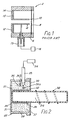
- the launcher 22 is made of an electrically conductive material, such as brass, and formed as a coaxial structure comprising an inner tube 26 and an outer tube 28.
- a first plate 30, at one end of the outer tube, provides a first end wall for the launcher structure.
- a second plate 31, integral with the outer tube 28, provides a second end wall.
- the inner tube 26 is shorter than the outer tube 28 and so positioned within the outer tube 28 as to define a first annular gap 32 and a second annular gap 33.
- the first plate 30 has an aperture for receiving the discharge tube 20.
- the outer tube 28, the first plate 30 and the second plate 31 form an unbroken electrically conductive path around, but not in electrical contact with, the inner tube 26 to provide an r.f. screening structure therearound.
- Suitable dimensions for the launcher of Figure 2 are as follows: Launcher length 7-20mm Launcher diameter (outer tube 28 diameter) 25-35mm but depends on size of discharge tube 20. Inner tube 26 length 3-18mm Inner tube 26 diameter 13mm but depends on size of discharge tube 20. Length of Launching gap (first gap 32) 0.5-3mm Length of second gap 33 1-10mm
- the thickness of the electrically conductive material is of the order of millimetres, or less, depending on the construction method used.
- An r.f. power generator 34 (shown schematically) is electrically connected to the launcher 22 via a coaxial cable 35 and an impedance matching network 36 (shown schematically) consisting of capacitors 36a and inductors 36b.
- the r.f. power generator 34, the impedance matching network 36, the coaxial cable 35 and the launcher 22 constitute an r.f. powered excitation device to energise the gas fill to produce a discharge.
- a dielectric material 37 is provided inside the launcher 22 either as a structural element, e.g. to keep the size of the gaps 32, 33 constant and/or to hold the inner tube 26 in position, and/or to help in shaping the electric field in the gaps 32, 33 for ease of starting or other purposes.
- Suitable dielectric materials which exhibit low loss at r.f. frequencies include glass, quartz and PTFE.
- an oscillating electric field having a frequency typically in the range of from 1MHz to 1GHz, is set up inside the launcher 22. At the first and second gaps 32, 33, this electric field is parallel to the longitudinal axis of the discharge tube 20. If sufficient power is applied, the consequent electric field produced in the gas fill 24 is sufficient to ionise the mercury to create a discharge through which an electromagnetic surface wave may be propagated in a similar manner to the arrangement of US-A-4 049 940. Accordingly, the launcher 22 powered by the r.f.
- power generator 34 creates and sustains a discharge in the fill - the length and brightness of the discharge depending, inter alia, on the size of the discharge tube 20 and the power applied by the r.f. power generator 34. Such a discharge tube arrangement may therefore be used as a light source.
- the first gap 32 and the second gap 33 each extend axially from respective ends of the inner tube 26, respectively to the first plate 30 and to the second plate 31.
- the discharge tube 20 extends from one end of the launcher 22 and so the first gap 32 is effective as a launching gap to create a discharge.
- the second gap 33 complements the effect of the first gap 32 and is advantageously larger than the first gap 32.
- Figure 2 also shows a helical structure 38, having 3 turns, and formed of an electrically conductive material, such as copper, extending along the discharge tube 20.
- An earth connection is provided from the structure 38 to the first plate 30 of the launcher 22.
- the effect of the helical structure 38 is to enhance the light output of the discharge tube arrangement.
- the helical structure 38 also provides some r.f. screening.
- FIG 3 shows an alternative embodiment of a launcher provided in accordance with the present invention.
- the launcher 40 is formed as a coaxial structure in a similar manner to the launcher 22 of Figure 2 and accordingly like parts are designated by like reference numerals.
- An aperture is also provided in the second plate 31 and accordingly the discharge tube (not shown) can be positioned to extend from both sides of the launcher 40.
- both the first gap 32 and the second gap 33 are effective as launching gaps to create a discharge. If the first and second gaps 32, 33 are the same size, this results in a relatively symmetrical discharge.
- the r.f. power at the second gap 33 is dissipated in the discharge and not lost from the system as in prior art launchers.
- the inside of the launcher 22 is shown as not filled with dielectric material for simplicity. Dielectric material may be present or, alternatively, the cable 35 may be sufficient to hold the inner tube 26 in position.
- An impedance - matching network 36′ is shown (schematically) outside the launcher 40.
- FIG. 4 Further embodiments of a launcher provided in accordance with the present invention are shown in Figures 4, 5a, 5b, 5c and 6a, 6b. Again, like parts are designated by like reference numerals.
- the embodiment of Figure 4 is the embodiment of Figure 3 modified so that the impedance matching network 36 (shown schematically) consisting of capacitors 36a and inductors 36b is provided inside the launcher - the coaxial cable 35 being connected directly to the r.f. power generator 34 - thus providing a more compact light source. It is also envisaged that part or all of the r.f. power generator may be positioned inside the launcher.
- Figures 5a, 5b and 5c show a dielectric material 51, 53, 55 provided inside the launcher 50, 52, 54, either as a structural element e.g. to keep the size of the gaps 32, 33 constant and/or to hold the inner tube in position, and/or to help in shaping the electric field in the gaps 32, 33 for ease of starting or other purposes.
- suitable dielectric materials which exhibit low loss at r.f. frequencies include glass, quartz and PTFE. The impedance-matching network for these embodiments has not been shown.
- Launchers 60, 62 having a structure similar to the launchers 40 and 22 of Figures 2 and 3 are shown in Figures 6a and 6b.
- a major difference lies in the provision of a flange 64 at one end of the inner tube 26.
- the flange 64 extends radially towards, but is not in electrical contact with, the outer tube 28.
- An annular disc 66 of dielectric material assists in holding the inner tube 26 in position.
- the first and the second gap have each extended axially from a respective end of the inner tube of the launcher. It is envisaged that the first and second gaps can also be provided as a launching gap extending from one end of the inner tube and a further gap adjacent and extending radially outward from the other end of the inner tube. Such an embodiment would also provide an r.f. screening structure around the inner tube without the further gap necessarily being in a position to act as a launching gap.
- launcher structures need not be limited to those in which both the inner and the outer tube are of circular cross-section.
- the inner and outer tubes could be of non-circular but similar cross-section or could be of dissimilar cross-section.
Landscapes
- Physics & Mathematics (AREA)
- Electromagnetism (AREA)
- Engineering & Computer Science (AREA)
- Plasma & Fusion (AREA)
- Discharge Lamps And Accessories Thereof (AREA)
- Vessels And Coating Films For Discharge Lamps (AREA)
- Lasers (AREA)
- X-Ray Techniques (AREA)
- Non-Portable Lighting Devices Or Systems Thereof (AREA)
- Electrical Discharge Machining, Electrochemical Machining, And Combined Machining (AREA)
Claims (9)
- Ankopplungstrichter, der bei Speisung mit Hochfrequenzleistung Oberflächenwellen in einer eine Füllung enthaltenden Entladungsröhre (20) anregt, enthaltend:
ein elektrisch leitfähiges Innenrohr (26),
ein elektrisch leitfähiges Außenrohr (28), das koaxial mit den Innenrohr (26) ist,
erste (30) und zweite (31) elektrisch leitfähige Endwände, wobei wenigstens eine der ersten (30) und zweiten (31) Endwände eine Öffnung zum Aufnehmen einer Entladungsröhre aufweist,
einen Trichterspalt (32), der in axialer Richtung von dem Ende des Innenrohres neben der ersten Wand (30) ausgeht,
und einen weiteren Spalt (33),
dadurch gekennzeichnet, daß die ersten und zweiten Endwände (30, 31) elektrisch leitfähig mit dem Außenrohr (28) zusammenhängen und der weitere Spalt (33) sich zwischen der zweiten Wand (31) und dem anderen Ende des Innenrohrs (26) erstreckt. - Ankopplungstrichter nach Anspruch 1, wobei der weitere Spalt (33) axial von dem anderen Ende des Innenrohrs (26) ausgeht (Figur 2).
- Ankopplungstrichter nach Anspruch 1, wobei der weitere Spalt (33) radial von dem anderen Ende des Innenrohrs ausgeht (Figur 6).
- Ankopplungstrichter nach einem der Ansprüche 1 bis 3, wobei sowohl die erste (30) als auch zweite (31) Endwand eine Öffnung aufweist zur Aufnahme einer Entladungsröhre (20).
- Ankopplungstrichter nach einem der Ansprüche 1 oder 3, wobei die zweite Endwand (31) einstückig mit dem Außenrohr (28) ist.
- Ankopplungstrichter nach einem der vorstehenden Ansprüche, wobei das Innenrohr (26) und das Außenrohr (28) einen ähnlichen Querschnitt haben.
- Ankopplungstrichter nach einem der vorstehenden Ansprüche, wobei wenigstens eine der Innen-(26) und Außenröhren (28) einen kreisförmigen Querschnitt hat.
- Einrichtung mit einem Hochfrequenz-Leistungsgenerator (34) und einem Ankopplungstrichter gemäß einem der vorstehenden Ansprüche zum Anregen von Oberflächenwellen in einer eine Füllung enthaltenden Entladungsröhre.
- Entladungsröhrenanordnung zur Verwendung als eine Lichtquelle mit einer Einrichtung gemäß Anspruch 8 und einer Entladungsröhre (20) aus einem lichtdurchlässigen dielektrischen Material, wobei die Röhre (20) eine Füllung (24) enthält.
Priority Applications (1)
| Application Number | Priority Date | Filing Date | Title |
|---|---|---|---|
| AT89308876T ATE102396T1 (de) | 1988-09-02 | 1989-09-01 | Entladungsroehren-system. |
Applications Claiming Priority (2)
| Application Number | Priority Date | Filing Date | Title |
|---|---|---|---|
| GB888821671A GB8821671D0 (en) | 1988-09-02 | 1988-09-02 | Discharge tube arrangement |
| GB8821671 | 1988-09-02 |
Publications (2)
| Publication Number | Publication Date |
|---|---|
| EP0357452A1 EP0357452A1 (de) | 1990-03-07 |
| EP0357452B1 true EP0357452B1 (de) | 1994-03-02 |
Family
ID=10643654
Family Applications (1)
| Application Number | Title | Priority Date | Filing Date |
|---|---|---|---|
| EP89308876A Expired - Lifetime EP0357452B1 (de) | 1988-09-02 | 1989-09-01 | Entladungsröhren-System |
Country Status (6)
| Country | Link |
|---|---|
| US (1) | US5065075A (de) |
| EP (1) | EP0357452B1 (de) |
| JP (1) | JPH02192608A (de) |
| AT (1) | ATE102396T1 (de) |
| DE (1) | DE68913395D1 (de) |
| GB (1) | GB8821671D0 (de) |
Families Citing this family (8)
| Publication number | Priority date | Publication date | Assignee | Title |
|---|---|---|---|---|
| GB8908604D0 (en) * | 1989-04-15 | 1989-06-01 | Emi Plc Thorn | A discharge tube arrangement |
| GB8915611D0 (en) * | 1989-07-07 | 1989-08-23 | Emi Plc Thorn | A discharge tube arrangement |
| US5239238A (en) * | 1991-05-08 | 1993-08-24 | U.S. Philips Corporation | Electrodeless low-pressure mercury vapour discharge lamp |
| EP0786798B1 (de) * | 1996-01-24 | 2002-04-24 | Matsushita Electric Industrial Co., Ltd. | Elektrodenlose Mikrowellenentladungslampe und Verfahren zur Fertigung einer derartigen Lampe |
| US5945790A (en) * | 1997-11-17 | 1999-08-31 | Schaefer; Raymond B. | Surface discharge lamp |
| US6118226A (en) * | 1998-07-31 | 2000-09-12 | Federal-Mogul World Wide, Inc. | Electrodeless neon light module for vehicle lighting systems |
| US6297583B1 (en) | 1998-10-08 | 2001-10-02 | Federal-Mogul World Wide, Inc. | Gas discharge lamp assembly with improved r.f. shielding |
| US6268699B1 (en) | 1999-02-09 | 2001-07-31 | Federal-Mogul World Wide, Inc. | Electrodeless gas discharge lamp assembly having transversely mounted envelope and method of manufacture |
Family Cites Families (5)
| Publication number | Priority date | Publication date | Assignee | Title |
|---|---|---|---|---|
| FR2290126A1 (fr) * | 1974-10-31 | 1976-05-28 | Anvar | Perfectionnements apportes aux dispositifs d'excitation, par des ondes hf, d'une colonne de gaz enfermee dans une enveloppe |
| FR2480552A1 (fr) * | 1980-04-10 | 1981-10-16 | Anvar | Generateur de plasma |
| JPS61114448A (ja) * | 1984-11-09 | 1986-06-02 | Hitachi Ltd | プラズマx線発生装置 |
| CA1246762A (en) * | 1985-07-05 | 1988-12-13 | Zenon Zakrzewski | Surface wave launchers to produce plasma columns and means for producing plasma of different shapes |
| US4792725A (en) * | 1985-12-10 | 1988-12-20 | The United States Of America As Represented By The Department Of Energy | Instantaneous and efficient surface wave excitation of a low pressure gas or gases |
-
1988
- 1988-09-02 GB GB888821671A patent/GB8821671D0/en active Pending
-
1989
- 1989-09-01 AT AT89308876T patent/ATE102396T1/de active
- 1989-09-01 DE DE89308876T patent/DE68913395D1/de not_active Expired - Lifetime
- 1989-09-01 EP EP89308876A patent/EP0357452B1/de not_active Expired - Lifetime
- 1989-09-01 US US07/401,415 patent/US5065075A/en not_active Expired - Fee Related
- 1989-09-02 JP JP1228172A patent/JPH02192608A/ja active Pending
Also Published As
| Publication number | Publication date |
|---|---|
| GB8821671D0 (en) | 1988-10-19 |
| EP0357452A1 (de) | 1990-03-07 |
| US5065075A (en) | 1991-11-12 |
| ATE102396T1 (de) | 1994-03-15 |
| JPH02192608A (ja) | 1990-07-30 |
| DE68913395D1 (de) | 1994-04-07 |
Similar Documents
| Publication | Publication Date | Title |
|---|---|---|
| EP0357453A1 (de) | Entladungsröhren-System | |
| US3942058A (en) | Electrodeless light source having improved arc shaping capability | |
| US4810933A (en) | Surface wave launchers to produce plasma columns and means for producing plasma of different shapes | |
| EP0003280B1 (de) | Wellenleitergaslaser mit einer Queranregungsentladung | |
| KR102018014B1 (ko) | 전자 결합 변압기 | |
| US4792725A (en) | Instantaneous and efficient surface wave excitation of a low pressure gas or gases | |
| EP0329143B1 (de) | Entladungslampe | |
| JP3196534B2 (ja) | マイクロ波放電光源装置 | |
| US6064154A (en) | Magnetron tuning using plasmas | |
| US4178534A (en) | Methods of and apparatus for electrodeless discharge excitation | |
| US3942068A (en) | Electrodeless light source with a termination fixture having an improved center conductor for arc shaping capability | |
| EP0357451B1 (de) | Entladungsröhren-System | |
| EP0357452B1 (de) | Entladungsröhren-System | |
| US3997816A (en) | Starting assist device for an electrodeless light source | |
| JP2014506379A (ja) | 半透明導波器電磁波プラズマ光源 | |
| US9041291B2 (en) | Lamp | |
| JP6379086B2 (ja) | 半透明導波路電磁波プラズマ光源 | |
| EP0416839A2 (de) | Entladungsröhrensystem | |
| US5070278A (en) | Discharge tube arrangement | |
| JPH088159B2 (ja) | プラズマ発生装置 | |
| EP0405816A2 (de) | Entladungsröhrensystem | |
| EP0438253A2 (de) | Entladungsröhrensystem | |
| WO1992000619A1 (en) | Asymmetric rf excited gas laser electrode configuration | |
| KR100517924B1 (ko) | 무전극 램프 시스템의 발광 촉진 장치 | |
| JPH0610972B2 (ja) | マイクロ波放電装置 |
Legal Events
| Date | Code | Title | Description |
|---|---|---|---|
| PUAI | Public reference made under article 153(3) epc to a published international application that has entered the european phase |
Free format text: ORIGINAL CODE: 0009012 |
|
| AK | Designated contracting states |
Kind code of ref document: A1 Designated state(s): AT BE CH DE ES FR GB GR IT LI LU NL SE |
|
| 17P | Request for examination filed |
Effective date: 19900504 |
|
| 17Q | First examination report despatched |
Effective date: 19920318 |
|
| RAP1 | Party data changed (applicant data changed or rights of an application transferred) |
Owner name: GE LIGHTING LIMITED |
|
| GRAA | (expected) grant |
Free format text: ORIGINAL CODE: 0009210 |
|
| AK | Designated contracting states |
Kind code of ref document: B1 Designated state(s): AT BE CH DE ES FR GB GR IT LI LU NL SE |
|
| PG25 | Lapsed in a contracting state [announced via postgrant information from national office to epo] |
Ref country code: IT Free format text: LAPSE BECAUSE OF FAILURE TO SUBMIT A TRANSLATION OF THE DESCRIPTION OR TO PAY THE FEE WITHIN THE PRE;WARNING: LAPSES OF ITALIAN PATENTS WITH EFFECTIVE DATE BEFORE 2007 MAY HAVE OCCURRED AT ANY TIME BEFORE 2007. THE CORRECT EFFECTIVE DATE MAY BE DIFFERENT FROM THE ONE RECORDED.SCRIBED TIME-LIMIT Effective date: 19940302 Ref country code: GR Free format text: LAPSE BECAUSE OF FAILURE TO SUBMIT A TRANSLATION OF THE DESCRIPTION OR TO PAY THE FEE WITHIN THE PRESCRIBED TIME-LIMIT Effective date: 19940302 Ref country code: AT Effective date: 19940302 Ref country code: DE Effective date: 19940302 Ref country code: CH Effective date: 19940302 Ref country code: SE Free format text: THE PATENT HAS BEEN ANNULLED BY A DECISION OF A NATIONAL AUTHORITY Effective date: 19940302 Ref country code: BE Effective date: 19940302 Ref country code: LI Effective date: 19940302 Ref country code: NL Effective date: 19940302 Ref country code: ES Free format text: THE PATENT HAS BEEN ANNULLED BY A DECISION OF A NATIONAL AUTHORITY Effective date: 19940302 Ref country code: FR Free format text: THE PATENT HAS BEEN ANNULLED BY A DECISION OF A NATIONAL AUTHORITY Effective date: 19940302 |
|
| REF | Corresponds to: |
Ref document number: 102396 Country of ref document: AT Date of ref document: 19940315 Kind code of ref document: T |
|
| REF | Corresponds to: |
Ref document number: 68913395 Country of ref document: DE Date of ref document: 19940407 |
|
| REG | Reference to a national code |
Ref country code: CH Ref legal event code: PL |
|
| EN | Fr: translation not filed | ||
| NLV1 | Nl: lapsed or annulled due to failure to fulfill the requirements of art. 29p and 29m of the patents act | ||
| PG25 | Lapsed in a contracting state [announced via postgrant information from national office to epo] |
Ref country code: LU Free format text: LAPSE BECAUSE OF NON-PAYMENT OF DUE FEES Effective date: 19940930 |
|
| PLBE | No opposition filed within time limit |
Free format text: ORIGINAL CODE: 0009261 |
|
| STAA | Information on the status of an ep patent application or granted ep patent |
Free format text: STATUS: NO OPPOSITION FILED WITHIN TIME LIMIT |
|
| 26N | No opposition filed | ||
| PGFP | Annual fee paid to national office [announced via postgrant information from national office to epo] |
Ref country code: GB Payment date: 20010821 Year of fee payment: 13 |
|
| REG | Reference to a national code |
Ref country code: GB Ref legal event code: IF02 |
|
| PG25 | Lapsed in a contracting state [announced via postgrant information from national office to epo] |
Ref country code: GB Free format text: LAPSE BECAUSE OF NON-PAYMENT OF DUE FEES Effective date: 20020901 |
|
| GBPC | Gb: european patent ceased through non-payment of renewal fee |
Effective date: 20020901 |