EP0357775A1 - Pallet replacing apparatus - Google Patents
Pallet replacing apparatus Download PDFInfo
- Publication number
- EP0357775A1 EP0357775A1 EP88903397A EP88903397A EP0357775A1 EP 0357775 A1 EP0357775 A1 EP 0357775A1 EP 88903397 A EP88903397 A EP 88903397A EP 88903397 A EP88903397 A EP 88903397A EP 0357775 A1 EP0357775 A1 EP 0357775A1
- Authority
- EP
- European Patent Office
- Prior art keywords
- pallet
- chain
- axis
- arrow
- along
- Prior art date
- Legal status (The legal status is an assumption and is not a legal conclusion. Google has not performed a legal analysis and makes no representation as to the accuracy of the status listed.)
- Granted
Links
- 238000010276 construction Methods 0.000 description 4
- 238000003754 machining Methods 0.000 description 2
- 230000035939 shock Effects 0.000 description 2
- 239000010730 cutting oil Substances 0.000 description 1
- 238000005520 cutting process Methods 0.000 description 1
- 238000004519 manufacturing process Methods 0.000 description 1
- 238000000034 method Methods 0.000 description 1
Images


Classifications
-
- B—PERFORMING OPERATIONS; TRANSPORTING
- B23—MACHINE TOOLS; METAL-WORKING NOT OTHERWISE PROVIDED FOR
- B23Q—DETAILS, COMPONENTS, OR ACCESSORIES FOR MACHINE TOOLS, e.g. ARRANGEMENTS FOR COPYING OR CONTROLLING; MACHINE TOOLS IN GENERAL CHARACTERISED BY THE CONSTRUCTION OF PARTICULAR DETAILS OR COMPONENTS; COMBINATIONS OR ASSOCIATIONS OF METAL-WORKING MACHINES, NOT DIRECTED TO A PARTICULAR RESULT
- B23Q7/00—Arrangements for handling work specially combined with or arranged in, or specially adapted for use in connection with, machine tools, e.g. for conveying, loading, positioning, discharging, sorting
- B23Q7/14—Arrangements for handling work specially combined with or arranged in, or specially adapted for use in connection with, machine tools, e.g. for conveying, loading, positioning, discharging, sorting co-ordinated in production lines
- B23Q7/1426—Arrangements for handling work specially combined with or arranged in, or specially adapted for use in connection with, machine tools, e.g. for conveying, loading, positioning, discharging, sorting co-ordinated in production lines with work holders not rigidly fixed to the transport devices
- B23Q7/1431—Work holder changers
-
- Y—GENERAL TAGGING OF NEW TECHNOLOGICAL DEVELOPMENTS; GENERAL TAGGING OF CROSS-SECTIONAL TECHNOLOGIES SPANNING OVER SEVERAL SECTIONS OF THE IPC; TECHNICAL SUBJECTS COVERED BY FORMER USPC CROSS-REFERENCE ART COLLECTIONS [XRACs] AND DIGESTS
- Y10—TECHNICAL SUBJECTS COVERED BY FORMER USPC
- Y10T—TECHNICAL SUBJECTS COVERED BY FORMER US CLASSIFICATION
- Y10T29/00—Metal working
- Y10T29/51—Plural diverse manufacturing apparatus including means for metal shaping or assembling
- Y10T29/5196—Multiple station with conveyor
Definitions
- This invention relates to a pallet changer suitable for use with a machine tool.
- FMS(flexible manufacturing system) has a machine tool and a pallet changer.
- the pallet changer exchanges a pallet on a table of the machine tool for another pallet.
- the conventional pallet changer is a hydraulic cylinder type or a chain type.
- a rod of the hydraulic cylinder is extended so that a pallet is settled on the table of the machine tool. After a work on the pallet is machined, the rod is contracted so that the pallet is returned.
- a plurality of pallets are set to the chain at regular intervals.
- the chain is drived by a motor so that the pallet is transfered to a pallet changing place near the table of the machine tool.
- the pallet changer When the large hydraulic cylinder or the large motor in the pallet changer starts or stops, the pallet changer is shocked.
- the shock is caused by the inertia of the heavy pallets and the works on the pallets.
- the large hydraulic cylinder and the large motor must be slowly operated.
- the object of this invention is to provide an improved pallet changer whose construction is simple. When this pallet changer is used, large cost saving are obtained.
- a pallet changer according to this invention is constructed as follows.
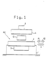
- Fig. 1 shows the pallet changer PC comprising a work carrier pallet 4 detachably and movably mounted to an table 2, and another work carrier pallet 14 set at a separate location (pallet'table 30 in an embodyment of Fig.2).
- the table 2 is provided on a support 1 (a support of machine tool in the embodiment) of the pallet changer.
- the table 2 moves along at least a first axis (the X-axis in the embodiment).
- the table 2 can reciprocately move along the first axis by means of drive means 3 such as a servomotor.
- the work carrier pallet 4 is detachably mounted to the table 2, and the work carrier can move on the table 2.
- a transfer means 12 transfers the work carrier pallet 4 on the table 2 in a first direction of arrow Xl and a second direction of arrow X2 opposite to the first direction.
- the pallet 4 moves by a drive power means 3 when the table 2 moves in the first direction of arrow Xl or the second direction of arrow X2.
- Pallet 4 is transfered by the drive means 3 only. No other drive means such as a hydraulic cylinder and a motor is required.
- the trnsfer means 12 has a guide body 62, a slide body 69, a first and a second sprocket 64, 65, a chain 66, an engagement means 67 and a mechanism part 100.
- the slide body 69 is supported by the guide body 62 fixed to the table 2 and can slide along the first axis.
- the first sprocket 64 and the second sprocket 65 are provided to one portion and another portion of the slide body 69.
- the chain 66 is set between the first and the second sprockets 64, 65.
- the chain 66 detachably engages the work carrier pallet 4.
- the mechanism part 100 drives the chain 66 so that the slide body 69 slides in the first direction of arrow Xl or in the second direction of arrow X2 relative to the table 2. Accordingly, the work carrier pallet 4 slides on the table 2 in the first direction of arrow Xl or in the second direction of arrow X2.
- the pallet moves in the same direction as the table's movement by means of the simple drive means such as the chain and the sprockets, so that a large hydraulic cylinder and a large motor are not required.
- the construction of the pallet changer according to this invention is simple and the pallet changer is small in size. Using the pallet changer according to this invention, large cost saving can be obtained.
- the pallet changer PC has a support 1 of a machine tool, a table 2, a drive means 3, a work carrier pallet 4 and a transfer means 12.
- the support 1 is settled on a floor.
- the table 2 is provided on the support 1.
- a work 5 is fixed to the work carrier pallet (hereinafter called the pallet for short) 4.
- the pallet 4 is mounted to the table 2 and movably along the X-axis.
- the table 2 can move along the X-axis, or in a first direction of arrow Xl or in a second direction of arrow X2 opposite to the first direction, by means of drive means 3 relative to the support 1.
- the transfer means 12 transfers the pallet 4 on the table 2 in the first direction of arrow Xl or in the second direction of arrow X2 when the table 2 moves in the first direction of arrow Xl or in the second direction of arrow X2.
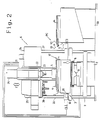
- Fig. 2 shows a vertical machining center equipped with the pallet changer according to this invention.
- the support 1 has a bed 7 and a saddle 8.
- a servo motor 9 (for a movement along the Y-axis) is attached to the bed.
- the drive means 3 has a servo moter 10 (for a movement along the X-axis) and a ball screw 11.
- the table 2 is attached on the saddle 8.
- the pallet 4 is mounted to the table 2 detachably and movably along the X-axis.
- the transfer means 12 provided near the table 2.
- a column 20 has a spindle head 21.
- a tool 23 is attached to a spindle 22 of the spindle head 21.
- the spindle 22 rotates by means of a motor 24.
- the spindle head has a automatic tool changer 25.
- the column 20 also has a control panel 26, a CNC unit 27 and a control boad 28.
- the table 2 can move in the first direction of arrow Xl or in the second direction of arrow X2 by means of servomotor 10.
- a pallet table 30 is placed beside the table 2.
- Another pallet 14 is placed on the pallet table 30.
- a feed screw 34 of a ball screw part 33 is connected to the servomoter 9.
- the feed screw engages a nut 35.
- the nut 35 is mounted to the under portion of the saddle 8 so that the the saddle 8 can move along the X-axis by means of the servomotor 9.
- the spindle head 21 can move along the Z-axis by means of a servomotor 31.
- Fig. 3 shows a part of the transfer means 12, which is hereinafter explained.
- Fig.4 illustrates that the pallets 4 and 14 can be set side by side on the pallet table 30.
- the work 5 is fixed to the pallet 4 and another work 5 is fixed to the pallet 14.
- the pallet table 30 is equipped with two air cylinders 40, 41.
- Each air cylinder 40, 41 has a stopper pin 42, 43.
- Each stopper pin 42, 43 can be inserted into a hole 44, 45 of the pallet 4, 14.
- the pallet 4, 14 is placed in precise position.
- the stopper pin 42, 43 is extracted from the hole 44, 45.
- a pallet hook 63 is attached to the front portion of the pallet 4 along the longitudinal direction of the pallet 4.
- a pallet hook 91 is attached to the pallet 14 in the same way.
- Fig. 5 shows the saddle 8, the table 2, the pallet 4 which is also called a pallet table, and the transfer means 12.
- Fig 6 shows the transfer means 12.
- Fig 7 is a perspective view showing the transfer means 12.
- Fig. 5 shows that the transfer means 12 has a guide body 62, a slide body 69, an engagement means 67, a chain 66, a first and a second sprocket 64 and 65, and a mechanism portion 100.
- the guide body 62 is fixed to a base bracket 61.
- the base bracket is fixed to the table 2.
- the cylindrical guide body 69 is slidably supported by the guide body 62.
- the slide body 69 can slide along X-axis.
- the first and second sprocket is provided to one end and the other end of the slide body 69, respectively.
- the chain is provided between the sprockets 64 and 65.
- the chain 66 has a chain hook 90 for engaging the engagement means 67 and a chain hook 68 for engaging the mechanism part 100.
- the engagement means comprises the pallet hook 63 and the chain hook 90.
- the chain hook 90 is fixed to the chain 66.
- the chain hook 90 of convex shape engages the pallet hook 63 of concave shape.
- the Y-axis is perpendicular to the X-axis.
- the chain hook 68 of concave shape is located above a stopper cylinder 92.
- the stopper cylinder 92 is upwardly fixed to the saddle 8.
- a pin 93 of the stopper cylinder 92 can be inserted into the chain hook 68.
- a rack 94 is fixed to the base bracket 61 along the X-axis.
- the rack 94 engages a pinion 95.
- the pinion 95 and the sprocket 64 are connencted to /or associated with to a shaft 96.
- the mechanism part 100 comprises the pinion 95, the rack 94, the chain hook 68 and the stopper pin 92.
- a proximity sensor 101 is associated with to the stopper cylinder 92. When the proximity sensor 101 detects the position of the chain hook 69, the pin 93 of the stopper cylinder 92 expands according to a command signal from the CNC device 27 (Fig. 2).
- the transfer mechanism 12 is covered by a cover 102.
- the pallet hook 63 is also covered by a cover 103. Because of these covers, cutting debris and a cutting oil can not enter inside these covers.
- Figs. 6 and 7 show the chain 66, the slide body 69, the guide body 62, the lack 94, the pinion 95, the sprocket 64, 65.
- the shaft 96 is rotatably attached to a connecting part 105.
- the connecting part 105 is fixed to one end of the slide body 69.
- a shaft 106 of the sprocket 65 is attached to the other end of the slide body 69.
- the tension of the chain 66 can be controlled.
- Fig. 8 is a sectional view taken along line A-A of Fig. 5.
- the table 2 in Fig. 8 has a slide portion 50, two clamp cylinders 51, a clamp unit 52, a clamp plate 53.
- the clamp unit 52 is fixed on the slide portion 50.
- One clamp cylinder 51 is located behind the other one.
- the clamp plate 53 is fixed to a rod 51a of the clamp cylinder 51.
- a nut 54 is fixed to an under surface of the slide portion 50.
- the feed screw 55 of the ball screw part 11 engages the nut 54.
- the feed screw 55 is connected to the servomoter 10.
- the transfer mechanism 12 comprises the chain 66, the sprocket 64, the slide body 69, the guide body 62, the chain hook 90, and the pallet hook 63.
- the clamp cylinder 92 is fixed to a bracket 57 which is fixed to the saddle 8.
- a pin 93 is guided by a pin guide 58.
- the chain hook 68 is located in a long groove 59 of the base bracket 61.
- Fig. 10 is a sectional view taken along line B-B of Fig. 5.
- the transfer mechanism 12 has the pinion 95, the rack 94, a connecting portion 105, the chain 66, and the sprocket 64.
- the pallet 4 is located on the pallet table 30.
- the table 2 is located at a right end of the saddle 8.
- the table 2 moves in the first direction of arrow Xl by means of the servomotor 10.
- the pin 93 of the clamp cylinder 92 engages the chain hook 68 of the chain 66.
- the chain 66 rotates in the counter-clockwise direction so that the pinion 95 moves on the rack 94 in the first direction of arrow Xl.
- the slide body 69 moves in the first direction of arrow Xl relative to the guide body 62 or the table 2.
- the pallet 4 is transfered from pallet stand to the table 2 as shown in Fig. 12.
- the pallet 4 is clamped at the table 2 as shown in Fig. 8.
- the pin 93 of the clamp cylinder 92 in Fig. 11 is removed from the chain hook 68.
- the table moves along the X-axis to machine the work 5
- the chain does not rotate. Accordingly, the pallet 4 does not move relative to the table 2.
- the work 5 is machined by predetermined tools.
- the table 2 is transfered from the place in Fig. 12 to the other place in Fig. 11 in the following manner.
- the pin 93 of the clamp cylinder 92 is engaged with the chain hook 68 of the chain 66.
- the pallet 4 is unclamped as shown in Fig. 9.
- the chain hook 90 engages the pallet hook 63.
- the table 2 is moved in the second direction of arrow X2 by means of the servomotor 10.
- the pin 93 of the clamp cylinder 92 engages the chain hook 68 of the chain 66.
- the chain 66 rotates clockwise so that the pinion moves in the second direction of arrow X2 in engaging with the rack 94.
- the slide member 69 moves in the direction of arrow X2 relative to the guide body 62 or the table 2.
- the chain hook 90 engages the pallet hook 63 so that the pallet 4 moves in the second direction of arrow X2 relative to the table 2 which moves in the direction of arrow X2.
- the pallet 4 is transfered from the table 2 to the pallet table 30 as shown in Fig. 11.
- the pallet 4 is located at the table 2, and the work 5 is machined, and the pallet is transfered to the pallet stand 30.
- the pallets 4, 14 are located on the pallet stand 30, and the table 2 is located in the initial position IP.
- the chain hook 90 is located at the left end of the chain 66.
- the table 2 moves in the second direction of arrow X2, and then next in the first direction of arrow Yl.
- the chain hook 90 moves at the right end of the chain 66 as shown in Fig. 14 and engages the pallet hook 63.
- the table 2 is then moved in the first direction of arrow Xl.
- the pallet 4 is located on the table 2.
- the table 2 is located at the machining position Pl.
- the spindle head 21 shown in Fig. 2 goes down so that a hole H (in Fig. 16) is machined in the work 5 by the tool 23.
- the table 2 is transfered to an another place SP.
- the table 2 moves in the second direction of arrow X2.
- the pallet moves in the second direction of arrow X2 relative to the table 2.
- Fig. 17 the pallet 4 is returned to the pallet stand 30.
- the table 2 is then moved in the direction of arrow Y2.
- the chain hook 90 disengages the pallet hook 63, and engages a pallet hook 91 of the pallet 14.
- the table 2 moves in the first direction of arrow Xl.
- the table 2 moves so that the pallet 14 also moves in the first direction of arrow Xl relative to the table 2.
- Fig. 19 the table 2 is transfered at the machining position Pl.
- the spindle head 21 in Fig. 2 goes down so that the work 5 is machined by a tool.
- the pallets 4 and 14 are located to the table 2 one by one, and the work 5 are machined.
- This invention is not restricted to the described embodiment.
- a plurality of pallets are provided on the pallet stand placed on .the side of the machining center.
- the table moves along the X-axis so that a plurality of pallets are exchanged.
- the pallet table can be settled in front of the vertical machining center, and a plurality of pallets can be placed on the pallet table. In this case, the table moves along the Y-axis so that the pallets are exchanged.
- the pallet table can be settled on the side of a horizontal machining center, and a plurality of pallets can be placed on the pallet stand. In this case, the table moves along the X-axis so that the pallets are exchanged.
- the pallet stand may be settled in front of the horizontal machining center. In this case, the table moves along the Z-axis so that the pallets are exchanged.
- the number of the pallets is not restricted to two. Three or more pallets may be used.
- the pallet changer according to this invention can be applied to a general industrial machine such as a automatic tool assembly machine with X, Y table as well as a machine tool.
- the table 2 moves along the Y-axis and accesses the pallet 4 and 14 one by one. Furthermore, the pallet 4 and 14 on the pallet stand 30 can be moved (along the Y-axis) relative to the table 2.
- This invention is useful as a pallet changer, and is compact in size and it's construction is simple.
Landscapes
- Engineering & Computer Science (AREA)
- Mechanical Engineering (AREA)
- Feeding Of Workpieces (AREA)
Abstract
Description
- This invention relates to a pallet changer suitable for use with a machine tool.
- FMS(flexible manufacturing system) has a machine tool and a pallet changer. The pallet changer exchanges a pallet on a table of the machine tool for another pallet. The conventional pallet changer is a hydraulic cylinder type or a chain type.
- In case of the pallet changer of a hydraulic cylinder type, a rod of the hydraulic cylinder is extended so that a pallet is settled on the table of the machine tool. After a work on the pallet is machined, the rod is contracted so that the pallet is returned.
- In case of the pallet changer of a chain type, a plurality of pallets are set to the chain at regular intervals. The chain is drived by a motor so that the pallet is transfered to a pallet changing place near the table of the machine tool.
- But, the pallets and the works are considerably heavy. In case of the pallet changer of a hydraulic cylinder type, a large hydraulic cylinder is needed. In case of the pallet changer of a chain type, a large motor and a big chain are needed. In both cases, the pallet changer is big in size and it's construction is complicated.
- When the large hydraulic cylinder or the large motor in the pallet changer starts or stops, the pallet changer is shocked. The shock is caused by the inertia of the heavy pallets and the works on the pallets. To avoid the shock, the large hydraulic cylinder and the large motor must be slowly operated.
- The object of this invention is to provide an improved pallet changer whose construction is simple. When this pallet changer is used, large cost saving are obtained.
- A pallet changer according to this invention, for example, is constructed as follows.
- Fig. 1 shows the pallet changer PC comprising a
work carrier pallet 4 detachably and movably mounted to an table 2, and anotherwork carrier pallet 14 set at a separate location (pallet'table 30 in an embodyment of Fig.2). The table 2 is provided on a support 1 (a support of machine tool in the embodiment) of the pallet changer. The table 2 moves along at least a first axis (the X-axis in the embodiment). The table 2 can reciprocately move along the first axis by means of drive means 3 such as a servomotor. Thework carrier pallet 4 is detachably mounted to the table 2, and the work carrier can move on the table 2. - A transfer means 12 transfers the
work carrier pallet 4 on the table 2 in a first direction of arrow Xl and a second direction of arrow X2 opposite to the first direction. Thepallet 4 moves by a drive power means 3 when the table 2 moves in the first direction of arrow Xl or the second direction of arrow X2. -
Pallet 4 is transfered by the drive means 3 only. No other drive means such as a hydraulic cylinder and a motor is required. - The trnsfer means 12 has a
guide body 62, aslide body 69, a first and asecond sprocket chain 66, an engagement means 67 and amechanism part 100. - The
slide body 69 is supported by theguide body 62 fixed to the table 2 and can slide along the first axis. Thefirst sprocket 64 and thesecond sprocket 65 are provided to one portion and another portion of theslide body 69. - The
chain 66 is set between the first and thesecond sprockets - By means of the engagement means 67, the
chain 66 detachably engages thework carrier pallet 4. - When the table 2 moves in the first direction of arrow Xl or in the second direction of arrow X2 by means of drive means 3, the
mechanism part 100 drives thechain 66 so that theslide body 69 slides in the first direction of arrow Xl or in the second direction of arrow X2 relative to the table 2. Accordingly, thework carrier pallet 4 slides on the table 2 in the first direction of arrow Xl or in the second direction of arrow X2. - In the pallet changer according to this invention, the pallet moves in the same direction as the table's movement by means of the simple drive means such as the chain and the sprockets, so that a large hydraulic cylinder and a large motor are not required. The construction of the pallet changer according to this invention is simple and the pallet changer is small in size. Using the pallet changer according to this invention, large cost saving can be obtained.
-
- Fig. 1 is a diagrammatic view showing a pallet changer according to this invention.
- Fig. 2 is a front view showing a machining center equipped with a pallet changer according to this invention.
- Fig. 3 is a side view showing the machining center.
- Fig. 4 is a perspective view showing a pallet table.
- Fig. 5 is a front view showing a transfer means and so on.
- Fig. 6 is a top view showing the transfer means.
- Fig. 7 is a perspective view showing the transfer means.
- Fig. 8 is a sectional view taken along line A-A of Fig. 5, in which a pallet is clamped.
- Fig. 9 is a sectional view in which the pallet is unclamped.
- Fig. 10 is a sectional view taken along B-B of Fig. 5.
- Fig. 11 is a view showing- the pallets on the pallet table.
- Fig. 12 is a view showing the pallet on the table.
- Fig. 13 to Fig. 19 are explanatory views showing pallet changing operations.
- In Fig. 1 the pallet changer PC has a
support 1 of a machine tool, a table 2, a drive means 3, awork carrier pallet 4 and a transfer means 12. - The
support 1 is settled on a floor. The table 2 is provided on thesupport 1. Awork 5 is fixed to the work carrier pallet (hereinafter called the pallet for short) 4. Thepallet 4 is mounted to the table 2 and movably along the X-axis. - The table 2 can move along the X-axis, or in a first direction of arrow Xl or in a second direction of arrow X2 opposite to the first direction, by means of drive means 3 relative to the
support 1. The transfer means 12 transfers thepallet 4 on the table 2 in the first direction of arrow Xl or in the second direction of arrow X2 when the table 2 moves in the first direction of arrow Xl or in the second direction of arrow X2. - Fig. 2 shows a vertical machining center equipped with the pallet changer according to this invention. The
support 1 has a bed 7 and asaddle 8. A servo motor 9 (for a movement along the Y-axis) is attached to the bed. - The drive means 3 has a servo moter 10 (for a movement along the X-axis) and a
ball screw 11. The table 2 is attached on thesaddle 8. Thepallet 4 is mounted to the table 2 detachably and movably along the X-axis. The transfer means 12 provided near the table 2. - A
column 20 has aspindle head 21. Atool 23 is attached to aspindle 22 of thespindle head 21. Thespindle 22 rotates by means of amotor 24. The spindle head has aautomatic tool changer 25. Thecolumn 20 also has acontrol panel 26, aCNC unit 27 and acontrol boad 28. - The table 2 can move in the first direction of arrow Xl or in the second direction of arrow X2 by means of
servomotor 10. A pallet table 30 is placed beside the table 2. Anotherpallet 14 is placed on the pallet table 30. - In Fig. 3, a
feed screw 34 of aball screw part 33 is connected to theservomoter 9. The feed screw engages anut 35. Thenut 35 is mounted to the under portion of thesaddle 8 so that the thesaddle 8 can move along the X-axis by means of theservomotor 9. Thespindle head 21 can move along the Z-axis by means of aservomotor 31. Fig. 3 shows a part of the transfer means 12, which is hereinafter explained. - Fig.4 illustrates that the
pallets work 5 is fixed to thepallet 4 and anotherwork 5 is fixed to thepallet 14. The pallet table 30 is equipped with two air cylinders 40, 41. Each air cylinder 40, 41 has astopper pin stopper pin hole pallet pallet pallet stopper pin hole - A
pallet hook 63 is attached to the front portion of thepallet 4 along the longitudinal direction of thepallet 4. Apallet hook 91 is attached to thepallet 14 in the same way. - Fig. 5 shows the
saddle 8, the table 2, thepallet 4 which is also called a pallet table, and the transfer means 12. Fig 6 shows the transfer means 12. Fig 7 is a perspective view showing the transfer means 12. - Fig. 5 shows that the transfer means 12 has a
guide body 62, aslide body 69, an engagement means 67, achain 66, a first and asecond sprocket mechanism portion 100. - The
guide body 62 is fixed to abase bracket 61. The base bracket is fixed to the table 2. Thecylindrical guide body 69 is slidably supported by theguide body 62. Theslide body 69 can slide along X-axis. - The first and second sprocket is provided to one end and the other end of the
slide body 69, respectively. The chain is provided between thesprockets - The
chain 66 has achain hook 90 for engaging the engagement means 67 and achain hook 68 for engaging themechanism part 100. The engagement means comprises thepallet hook 63 and thechain hook 90. Thechain hook 90 is fixed to thechain 66. Thechain hook 90 of convex shape engages thepallet hook 63 of concave shape. When thepallet hook 63 moves along the Y-axis (Fig. 3) relative to thechain hook 90, thepallet hook 63 disengages from thechain hook 90. The Y-axis is perpendicular to the X-axis. - The
chain hook 68 of concave shape is located above astopper cylinder 92. Thestopper cylinder 92 is upwardly fixed to thesaddle 8. Apin 93 of thestopper cylinder 92 can be inserted into thechain hook 68. - A
rack 94 is fixed to thebase bracket 61 along the X-axis. Therack 94 engages apinion 95. Thepinion 95 and thesprocket 64 are connencted to /or associated with to ashaft 96. - The
mechanism part 100 comprises thepinion 95, therack 94, thechain hook 68 and thestopper pin 92. A proximity sensor 101 is associated with to thestopper cylinder 92. When the proximity sensor 101 detects the position of thechain hook 69, thepin 93 of thestopper cylinder 92 expands according to a command signal from the CNC device 27 (Fig. 2). - The
transfer mechanism 12 is covered by acover 102. Thepallet hook 63 is also covered by acover 103. Because of these covers, cutting debris and a cutting oil can not enter inside these covers. - Figs. 6 and 7 show the
chain 66, theslide body 69, theguide body 62, thelack 94, thepinion 95, thesprocket shaft 96 is rotatably attached to a connectingpart 105. The connectingpart 105 is fixed to one end of theslide body 69. - A
shaft 106 of thesprocket 65 is attached to the other end of theslide body 69. When the shaft is shifted by adjustingscrews chain 66 can be controlled. - Fig. 8 is a sectional view taken along line A-A of Fig. 5. The table 2 in Fig. 8 has a
slide portion 50, twoclamp cylinders 51, aclamp unit 52, aclamp plate 53. Theclamp unit 52 is fixed on theslide portion 50. Oneclamp cylinder 51 is located behind the other one. Theclamp plate 53 is fixed to arod 51a of theclamp cylinder 51. Anut 54 is fixed to an under surface of theslide portion 50. Thefeed screw 55 of the ball screwpart 11 engages thenut 54. Thefeed screw 55 is connected to theservomoter 10. - In Fig. 8, the
rod 51a of theclamp cylinder 51 is contracted. The clamp plate clamps thepallet 4 againstpins - In Fig. 8, the
transfer mechanism 12 comprises thechain 66, thesprocket 64, theslide body 69, theguide body 62, thechain hook 90, and thepallet hook 63. Theclamp cylinder 92 is fixed to abracket 57 which is fixed to thesaddle 8. Apin 93 is guided by apin guide 58. Thechain hook 68 is located in along groove 59 of thebase bracket 61. - In Fig. 9, the
rod 51a of theclamp cylinder 51 expands and theclamp plate 53 unclamps thepallet 4. In this condition, the table 2 can move along thesaddle 8 by means ofservomotor 10. - Fig. 10 is a sectional view taken along line B-B of Fig. 5. In Fig. 10, the
transfer mechanism 12 has thepinion 95, therack 94, a connectingportion 105, thechain 66, and thesprocket 64. - In Fig. 11, the
pallet 4 is located on the pallet table 30. The table 2 is located at a right end of thesaddle 8. The table 2 moves in the first direction of arrow Xl by means of theservomotor 10. In this case, thepin 93 of theclamp cylinder 92 engages thechain hook 68 of thechain 66. Thechain 66 rotates in the counter-clockwise direction so that thepinion 95 moves on therack 94 in the first direction of arrow Xl. Theslide body 69 moves in the first direction of arrow Xl relative to theguide body 62 or the table 2. When thechain hook 90 engages thepallet hook 63 and the table 2 moves in the first direction of arrow Xl, thepallet 2 moves in the first direction of arrow Xl relative to table 2. - In such a manner, the
pallet 4 is transfered from pallet stand to the table 2 as shown in Fig. 12. - The
pallet 4 is clamped at the table 2 as shown in Fig. 8. Thepin 93 of theclamp cylinder 92 in Fig. 11 is removed from thechain hook 68. When the table moves along the X-axis to machine thework 5, the chain does not rotate. Accordingly, thepallet 4 does not move relative to the table 2. - The
work 5 is machined by predetermined tools. - After the work is machined, the table 2 is transfered from the place in Fig. 12 to the other place in Fig. 11 in the following manner. The
pin 93 of theclamp cylinder 92 is engaged with thechain hook 68 of thechain 66. Thepallet 4 is unclamped as shown in Fig. 9. In this condition, thechain hook 90 engages thepallet hook 63. The table 2 is moved in the second direction of arrow X2 by means of theservomotor 10. At this time, thepin 93 of theclamp cylinder 92 engages thechain hook 68 of thechain 66. Thechain 66 rotates clockwise so that the pinion moves in the second direction of arrow X2 in engaging with therack 94. Theslide member 69 moves in the direction of arrow X2 relative to theguide body 62 or the table 2. Thechain hook 90 engages thepallet hook 63 so that thepallet 4 moves in the second direction of arrow X2 relative to the table 2 which moves in the direction of arrow X2. - Thus, the
pallet 4 is transfered from the table 2 to the pallet table 30 as shown in Fig. 11. - By the before-mentioned manner, the
pallet 4 is located at the table 2, and thework 5 is machined, and the pallet is transfered to thepallet stand 30. - The process to transfer the
pallet 4 and thepallet 14 to the table 2 is explained by referring to Fig. 13 and 19. - In Fig. 13, the
pallets pallet stand 30, and the table 2 is located in the initial position IP. Thechain hook 90 is located at the left end of thechain 66. The table 2 moves in the second direction of arrow X2, and then next in the first direction of arrow Yl. - Accordingly, the
chain hook 90 moves at the right end of thechain 66 as shown in Fig. 14 and engages thepallet hook 63. The table 2 is then moved in the first direction of arrow Xl. - In Fig. 15, the
pallet 4 is located on the table 2. The table 2 is located at the machining position Pl. Thespindle head 21 shown in Fig. 2 goes down so that a hole H (in Fig. 16) is machined in thework 5 by thetool 23. - In Fig. 16, after the
work 5 is machined, the table 2 is transfered to an another place SP. The table 2 moves in the second direction of arrow X2. When the table 2 moves, the pallet moves in the second direction of arrow X2 relative to the table 2. - In Fig. 17, the
pallet 4 is returned to thepallet stand 30. The table 2 is then moved in the direction of arrow Y2. - As seen in Fig. 18 the
chain hook 90 disengages thepallet hook 63, and engages apallet hook 91 of thepallet 14. The table 2 moves in the first direction of arrow Xl. The table 2 moves so that thepallet 14 also moves in the first direction of arrow Xl relative to the table 2. - In Fig. 19 the table 2 is transfered at the machining position Pl. The
spindle head 21 in Fig. 2 goes down so that thework 5 is machined by a tool. In this a manner, thepallets work 5 are machined. - This invention is not restricted to the described embodiment. In case of the before-mentioned vertical machining center, a plurality of pallets are provided on the pallet stand placed on .the side of the machining center. The table moves along the X-axis so that a plurality of pallets are exchanged. The pallet table can be settled in front of the vertical machining center, and a plurality of pallets can be placed on the pallet table. In this case, the table moves along the Y-axis so that the pallets are exchanged.
- Further, the pallet table can be settled on the side of a horizontal machining center, and a plurality of pallets can be placed on the pallet stand. In this case, the table moves along the X-axis so that the pallets are exchanged. The pallet stand may be settled in front of the horizontal machining center. In this case, the table moves along the Z-axis so that the pallets are exchanged.
- The number of the pallets is not restricted to two. Three or more pallets may be used.
- Furthermore, the pallet changer according to this invention can be applied to a general industrial machine such as a automatic tool assembly machine with X, Y table as well as a machine tool.
- In the embodiment in the drawings, the table 2 moves along the Y-axis and accesses the
pallet pallet - This invention is useful as a pallet changer, and is compact in size and it's construction is simple.
Claims (3)
Applications Claiming Priority (3)
| Application Number | Priority Date | Filing Date | Title |
|---|---|---|---|
| JP62109837A JPS63278738A (en) | 1987-05-07 | 1987-05-07 | Pallet exchange device |
| JP109837/87 | 1987-05-07 | ||
| PCT/JP1988/000400 WO1988008770A1 (en) | 1987-05-07 | 1988-04-25 | Pallet replacing apparatus |
Publications (3)
| Publication Number | Publication Date |
|---|---|
| EP0357775A1 true EP0357775A1 (en) | 1990-03-14 |
| EP0357775A4 EP0357775A4 (en) | 1992-03-25 |
| EP0357775B1 EP0357775B1 (en) | 1997-01-22 |
Family
ID=14520462
Family Applications (1)
| Application Number | Title | Priority Date | Filing Date |
|---|---|---|---|
| EP88903397A Expired - Lifetime EP0357775B1 (en) | 1987-05-07 | 1988-04-25 | Pallet replacing apparatus |
Country Status (5)
| Country | Link |
|---|---|
| US (2) | US4996754A (en) |
| EP (1) | EP0357775B1 (en) |
| JP (1) | JPS63278738A (en) |
| DE (1) | DE3855768T2 (en) |
| WO (1) | WO1988008770A1 (en) |
Cited By (6)
| Publication number | Priority date | Publication date | Assignee | Title |
|---|---|---|---|---|
| EP0466062A1 (en) * | 1990-07-12 | 1992-01-15 | Kitamura Machinery Co.,Ltd. | A pallet changer |
| EP0428193A3 (en) * | 1989-11-15 | 1992-02-26 | Salvagnini S.P.A. | Equipment for machining pieces on a pallet by means of a machine tool with a single device for the transfer of pallets between a work station and an adjacent station for loading/unloading the pallets |
| DE19826507A1 (en) * | 1998-06-15 | 1999-12-16 | Wilfried Taubner | Flexible finishing module for processing workpieces |
| EP2481520A4 (en) * | 2009-09-22 | 2013-07-24 | Doosan Infracore Co Ltd | Pallet conveying device of horizontal machining center |
| EP3520957A1 (en) | 2018-02-02 | 2019-08-07 | Etablissements Oger | Device for handling parts stored on pallets positionable in the vicinity of a machining centre |
| KR102710568B1 (en) * | 2024-05-22 | 2024-09-26 | 서암기계공업주식회사 | Automatic pallet exchanger of machine tool |
Families Citing this family (19)
| Publication number | Priority date | Publication date | Assignee | Title |
|---|---|---|---|---|
| JPS63318236A (en) * | 1987-06-19 | 1988-12-27 | Kitamura Mach Co Ltd | Device for replacing pallet |
| DE4235344C2 (en) * | 1991-10-21 | 1998-01-29 | Honda Motor Co Ltd | Device for transferring and positioning a pallet that can be loaded with a workpiece |
| IT1251254B (en) * | 1991-11-08 | 1995-05-05 | Pluritec Italia | METHOD AND EQUIPMENT FOR LOADING AND UNLOADING OF PIECES FOR A MACHINE TOOL, PARTICULARLY FOR THE PROCESSING OF PRINTED CIRCUIT PLATES. |
| US5370212A (en) * | 1991-12-04 | 1994-12-06 | Toshiba Kikai Kabushiki Kaisha | Automatic pallet changer method and apparatus |
| JPH07308835A (en) * | 1994-05-14 | 1995-11-28 | Heian Corp | Table exchange device for nc rooter |
| US5653014A (en) * | 1994-09-13 | 1997-08-05 | Axis Usa, Inc. | Dynamo-electric machine component conveying systems and load/unload devices |
| US5813514A (en) * | 1995-12-19 | 1998-09-29 | Midaco Corporation | Automated end loading pallet system |
| US5810541A (en) * | 1996-05-21 | 1998-09-22 | International Paper Box Machine Co., Inc. | Apparatus and method for manually exchanging pallets |
| US5997241A (en) * | 1997-03-24 | 1999-12-07 | Midaco Corporation | Automatic pallet loading system and a method for loading pallets |
| US6193048B1 (en) * | 1998-11-24 | 2001-02-27 | Midaco Corporation | Pallet changer |
| US6213279B1 (en) * | 1999-07-15 | 2001-04-10 | Pilot Industries, Inc. | Machine for selectively positioning a work member at a work station |
| US6308815B1 (en) | 1999-10-15 | 2001-10-30 | Midaco Corporation | Rotatable pallet changing apparatus, system and method |
| US7975998B2 (en) * | 2006-04-03 | 2011-07-12 | Midaco Corporation | Pallet changer and system and method for using the same |
| CN102785121A (en) * | 2012-08-31 | 2012-11-21 | 昆山隆正机电科技有限公司 | Small part clamping and shifting device and method thereof |
| USD692934S1 (en) * | 2012-09-05 | 2013-11-05 | Jtekt Corporation | Pallet changer for machine tool |
| USD691183S1 (en) * | 2012-09-05 | 2013-10-08 | Jtekt Corporation | Pallet for machine tool |
| US9144870B2 (en) * | 2012-09-07 | 2015-09-29 | Midaco Corporation | Rotary pallet pool |
| CN106903543B (en) * | 2017-04-19 | 2023-05-05 | 上海美诺福科技有限公司 | Machining center and machining system |
| CN108453556A (en) * | 2018-03-29 | 2018-08-28 | 宁波海天精工股份有限公司 | A kind of machining center work-table exchange set |
Family Cites Families (11)
| Publication number | Priority date | Publication date | Assignee | Title |
|---|---|---|---|---|
| DE265580C (en) * | ||||
| US4172512A (en) * | 1977-08-24 | 1979-10-30 | Kearney & Trecker Corporation | Machine tool with common drive for worktable and pallet shuttle |
| JPS6021156Y2 (en) * | 1980-09-05 | 1985-06-24 | 株式會社牧野フライス製作所 | Pallet changing device for numerically controlled machine tools |
| JPS57173938A (en) * | 1981-04-20 | 1982-10-26 | Toshiba Corp | Manufacture of semiconductor device |
| JPS624437Y2 (en) * | 1981-04-30 | 1987-01-31 | ||
| JPS5851009A (en) * | 1981-09-24 | 1983-03-25 | Toyoda Mach Works Ltd | Machine tool equipped with pallet exchanger |
| JPS6113937A (en) * | 1984-06-28 | 1986-01-22 | ミツチエル ピー ドムブロウスキ | Blood sampling instrument for embryo |
| JP2521692B2 (en) * | 1987-02-23 | 1996-08-07 | 株式会社 松浦機械製作所 | Pallet changer for machine tools |
| JPS63256332A (en) * | 1987-04-14 | 1988-10-24 | Kitamura Mach Co Ltd | Pallet exchanger |
| JPS63318236A (en) * | 1987-06-19 | 1988-12-27 | Kitamura Mach Co Ltd | Device for replacing pallet |
| DD265580A1 (en) * | 1987-11-04 | 1989-03-08 | Werkzeugmasch Forschzent | DEVICE FOR AUTOMATIC TRANSFER AND SUBMISSION OF EXAMPLE PALLETS |
-
1987
- 1987-05-07 JP JP62109837A patent/JPS63278738A/en active Granted
-
1988
- 1988-04-25 EP EP88903397A patent/EP0357775B1/en not_active Expired - Lifetime
- 1988-04-25 US US07/434,674 patent/US4996754A/en not_active Expired - Lifetime
- 1988-04-25 DE DE3855768T patent/DE3855768T2/en not_active Expired - Fee Related
- 1988-04-25 WO PCT/JP1988/000400 patent/WO1988008770A1/en not_active Ceased
-
1990
- 1990-10-02 US US07/591,827 patent/US5062190A/en not_active Expired - Lifetime
Non-Patent Citations (2)
| Title |
|---|
| No further revelant documents have been disclosed. * |
| See also references of WO8808770A1 * |
Cited By (6)
| Publication number | Priority date | Publication date | Assignee | Title |
|---|---|---|---|---|
| EP0428193A3 (en) * | 1989-11-15 | 1992-02-26 | Salvagnini S.P.A. | Equipment for machining pieces on a pallet by means of a machine tool with a single device for the transfer of pallets between a work station and an adjacent station for loading/unloading the pallets |
| EP0466062A1 (en) * | 1990-07-12 | 1992-01-15 | Kitamura Machinery Co.,Ltd. | A pallet changer |
| DE19826507A1 (en) * | 1998-06-15 | 1999-12-16 | Wilfried Taubner | Flexible finishing module for processing workpieces |
| EP2481520A4 (en) * | 2009-09-22 | 2013-07-24 | Doosan Infracore Co Ltd | Pallet conveying device of horizontal machining center |
| EP3520957A1 (en) | 2018-02-02 | 2019-08-07 | Etablissements Oger | Device for handling parts stored on pallets positionable in the vicinity of a machining centre |
| KR102710568B1 (en) * | 2024-05-22 | 2024-09-26 | 서암기계공업주식회사 | Automatic pallet exchanger of machine tool |
Also Published As
| Publication number | Publication date |
|---|---|
| WO1988008770A1 (en) | 1988-11-17 |
| US5062190A (en) | 1991-11-05 |
| US4996754A (en) | 1991-03-05 |
| EP0357775B1 (en) | 1997-01-22 |
| EP0357775A4 (en) | 1992-03-25 |
| DE3855768T2 (en) | 1997-06-26 |
| JPS63278738A (en) | 1988-11-16 |
| JPH0346252B2 (en) | 1991-07-15 |
| DE3855768D1 (en) | 1997-03-06 |
Similar Documents
| Publication | Publication Date | Title |
|---|---|---|
| EP0357775A1 (en) | Pallet replacing apparatus | |
| US4995502A (en) | Pallet changer | |
| US5054175A (en) | Machine tool having automatic changeable tables | |
| EP1116548A2 (en) | A machine tool having a vertical main spindle and a method of making the same | |
| CA2218624C (en) | Method and apparatus for machining holes in crankshafts | |
| US5044486A (en) | Pallet magazine | |
| EP1731260A1 (en) | Machine tool apparatus having pallet changer | |
| KR870004782A (en) | Numerical Control Machine | |
| US4715490A (en) | Automatic pallet changer | |
| US5145048A (en) | Pallet changer | |
| EP1652618B1 (en) | Clamping mechanism for pallet changer | |
| EP0483781A2 (en) | Tool magazine | |
| JPH0620706B2 (en) | Pallet replacement method | |
| US5187846A (en) | Pallet changer | |
| KR20080108199A (en) | Multipurpose Engraver | |
| JPS63109931A (en) | vertical machining center | |
| JPS591523B2 (en) | Processing unit device with variable angle | |
| JPH0671690B2 (en) | Pallet changer | |
| JPH0346251B2 (en) | ||
| JPH0197543A (en) | Pallet exchange method | |
| JPH0630356Y2 (en) | Tool changer | |
| JPS5810185B2 (en) | Automatic pallet exchange metal cutting machine | |
| JPH0445294B2 (en) | ||
| JPH0679559A (en) | Punch-laser compound finishing machine | |
| JPS6059106B2 (en) | Fixed position stop device for mobile machine base |
Legal Events
| Date | Code | Title | Description |
|---|---|---|---|
| PUAI | Public reference made under article 153(3) epc to a published international application that has entered the european phase |
Free format text: ORIGINAL CODE: 0009012 |
|
| 17P | Request for examination filed |
Effective date: 19891005 |
|
| AK | Designated contracting states |
Kind code of ref document: A1 Designated state(s): CH DE FR GB IT LI NL |
|
| A4 | Supplementary search report drawn up and despatched |
Effective date: 19920131 |
|
| AK | Designated contracting states |
Kind code of ref document: A4 Designated state(s): CH DE FR GB IT LI NL |
|
| 17Q | First examination report despatched |
Effective date: 19950327 |
|
| GRAG | Despatch of communication of intention to grant |
Free format text: ORIGINAL CODE: EPIDOS AGRA |
|
| GRAH | Despatch of communication of intention to grant a patent |
Free format text: ORIGINAL CODE: EPIDOS IGRA |
|
| GRAH | Despatch of communication of intention to grant a patent |
Free format text: ORIGINAL CODE: EPIDOS IGRA |
|
| GRAA | (expected) grant |
Free format text: ORIGINAL CODE: 0009210 |
|
| AK | Designated contracting states |
Kind code of ref document: B1 Designated state(s): CH DE FR GB IT LI NL |
|
| REG | Reference to a national code |
Ref country code: CH Ref legal event code: NV Representative=s name: TROESCH SCHEIDEGGER WERNER AG Ref country code: CH Ref legal event code: EP |
|
| REF | Corresponds to: |
Ref document number: 3855768 Country of ref document: DE Date of ref document: 19970306 |
|
| ET | Fr: translation filed | ||
| ITF | It: translation for a ep patent filed | ||
| PLBE | No opposition filed within time limit |
Free format text: ORIGINAL CODE: 0009261 |
|
| STAA | Information on the status of an ep patent application or granted ep patent |
Free format text: STATUS: NO OPPOSITION FILED WITHIN TIME LIMIT |
|
| 26N | No opposition filed | ||
| REG | Reference to a national code |
Ref country code: GB Ref legal event code: IF02 |
|
| PGFP | Annual fee paid to national office [announced via postgrant information from national office to epo] |
Ref country code: NL Payment date: 20020416 Year of fee payment: 15 Ref country code: FR Payment date: 20020416 Year of fee payment: 15 |
|
| PGFP | Annual fee paid to national office [announced via postgrant information from national office to epo] |
Ref country code: CH Payment date: 20020422 Year of fee payment: 15 |
|
| PG25 | Lapsed in a contracting state [announced via postgrant information from national office to epo] |
Ref country code: LI Free format text: LAPSE BECAUSE OF NON-PAYMENT OF DUE FEES Effective date: 20030430 Ref country code: CH Free format text: LAPSE BECAUSE OF NON-PAYMENT OF DUE FEES Effective date: 20030430 |
|
| PG25 | Lapsed in a contracting state [announced via postgrant information from national office to epo] |
Ref country code: NL Free format text: LAPSE BECAUSE OF NON-PAYMENT OF DUE FEES Effective date: 20031101 |
|
| NLV4 | Nl: lapsed or anulled due to non-payment of the annual fee |
Effective date: 20031101 |
|
| REG | Reference to a national code |
Ref country code: CH Ref legal event code: PL |
|
| PG25 | Lapsed in a contracting state [announced via postgrant information from national office to epo] |
Ref country code: FR Free format text: LAPSE BECAUSE OF NON-PAYMENT OF DUE FEES Effective date: 20031231 |
|
| REG | Reference to a national code |
Ref country code: FR Ref legal event code: ST |
|
| PGFP | Annual fee paid to national office [announced via postgrant information from national office to epo] |
Ref country code: GB Payment date: 20050414 Year of fee payment: 18 |
|
| PGFP | Annual fee paid to national office [announced via postgrant information from national office to epo] |
Ref country code: DE Payment date: 20050527 Year of fee payment: 18 |
|
| PG25 | Lapsed in a contracting state [announced via postgrant information from national office to epo] |
Ref country code: GB Free format text: LAPSE BECAUSE OF NON-PAYMENT OF DUE FEES Effective date: 20060425 |
|
| PGFP | Annual fee paid to national office [announced via postgrant information from national office to epo] |
Ref country code: IT Payment date: 20060430 Year of fee payment: 19 |
|
| PG25 | Lapsed in a contracting state [announced via postgrant information from national office to epo] |
Ref country code: DE Free format text: LAPSE BECAUSE OF NON-PAYMENT OF DUE FEES Effective date: 20061101 |
|
| GBPC | Gb: european patent ceased through non-payment of renewal fee |
Effective date: 20060425 |
|
| PG25 | Lapsed in a contracting state [announced via postgrant information from national office to epo] |
Ref country code: IT Free format text: LAPSE BECAUSE OF NON-PAYMENT OF DUE FEES Effective date: 20070425 |