EP0357809B1 - Rotierende Filtertrommel für Fest-Flüssig-Trennung - Google Patents
Rotierende Filtertrommel für Fest-Flüssig-Trennung Download PDFInfo
- Publication number
- EP0357809B1 EP0357809B1 EP88114056A EP88114056A EP0357809B1 EP 0357809 B1 EP0357809 B1 EP 0357809B1 EP 88114056 A EP88114056 A EP 88114056A EP 88114056 A EP88114056 A EP 88114056A EP 0357809 B1 EP0357809 B1 EP 0357809B1
- Authority
- EP
- European Patent Office
- Prior art keywords
- filter cloth
- drum
- filtration drum
- solid
- solids
- Prior art date
- Legal status (The legal status is an assumption and is not a legal conclusion. Google has not performed a legal analysis and makes no representation as to the accuracy of the status listed.)
- Expired - Lifetime
Links
Images


Classifications
-
- B—PERFORMING OPERATIONS; TRANSPORTING
- B01—PHYSICAL OR CHEMICAL PROCESSES OR APPARATUS IN GENERAL
- B01D—SEPARATION
- B01D33/00—Filters with filtering elements which move during the filtering operation
- B01D33/06—Filters with filtering elements which move during the filtering operation with rotary cylindrical filtering surfaces, e.g. hollow drums
- B01D33/067—Construction of the filtering drums, e.g. mounting or sealing arrangements
-
- B—PERFORMING OPERATIONS; TRANSPORTING
- B01—PHYSICAL OR CHEMICAL PROCESSES OR APPARATUS IN GENERAL
- B01D—SEPARATION
- B01D33/00—Filters with filtering elements which move during the filtering operation
- B01D33/06—Filters with filtering elements which move during the filtering operation with rotary cylindrical filtering surfaces, e.g. hollow drums
- B01D33/11—Filters with filtering elements which move during the filtering operation with rotary cylindrical filtering surfaces, e.g. hollow drums arranged for outward flow filtration
-
- B—PERFORMING OPERATIONS; TRANSPORTING
- B01—PHYSICAL OR CHEMICAL PROCESSES OR APPARATUS IN GENERAL
- B01D—SEPARATION
- B01D33/00—Filters with filtering elements which move during the filtering operation
- B01D33/44—Regenerating the filter material in the filter
- B01D33/46—Regenerating the filter material in the filter by scrapers, brushes nozzles or the like acting on the cake-side of the filtering element
- B01D33/463—Regenerating the filter material in the filter by scrapers, brushes nozzles or the like acting on the cake-side of the filtering element nozzles
-
- B—PERFORMING OPERATIONS; TRANSPORTING
- B01—PHYSICAL OR CHEMICAL PROCESSES OR APPARATUS IN GENERAL
- B01D—SEPARATION
- B01D33/00—Filters with filtering elements which move during the filtering operation
- B01D33/70—Filters with filtering elements which move during the filtering operation having feed or discharge devices
- B01D33/74—Filters with filtering elements which move during the filtering operation having feed or discharge devices for discharging filtrate
-
- B—PERFORMING OPERATIONS; TRANSPORTING
- B01—PHYSICAL OR CHEMICAL PROCESSES OR APPARATUS IN GENERAL
- B01D—SEPARATION
- B01D33/00—Filters with filtering elements which move during the filtering operation
- B01D33/80—Accessories
- B01D33/804—Accessories integrally combined with devices for controlling the filtration
- B01D33/807—Accessories integrally combined with devices for controlling the filtration by level measuring
Definitions
- the raised fibers with a large diameter are rigid and unyielding, and consequently the space between the fibers is large and deep. Further, the number of the raised fibers is so small that the surface of the woven material is visible, and, in some cases, the fibers become curled and make the filter layer bulky. Therefore, if solids enter the space between the raised fibers while being deformed, they will not easily come out of the space. As a result, the filter cloth becomes clogged and impairs the treating ability of the apparatus. Clogging of the filter cloth is particularly noticeable when the rigid fibers penetrate the solids.
- the primary object of the invention is to provide a rotary drum type solid-liquid separation apparatus which is excellent in the solid-liquid separation performance, facilitates withdrawal of the solid content arrested by the filter medium, and which can be operated continuously for a long period of time while preventing the filter medium from becoming clogged.
- Another object of the invention is to provide a rotary drum type solid-liquid separation apparatus equipped with a filter medium which is less abraded or damaged, and the service life of which is prolonged, thus requiring fewer replacement with new one.
- filter cloth having a raised fiber layer which is formed by napping the weft of the base material in one direction along the length of the material to create flexible and yielding naps of a diameter of 0.1 to 10 »m is used with a solid-liquid separation apparatus, the naps lie and form a very fine filter layer at the time of solid-liquid separation, to arrest fine solids contained in the solid-liquid mixture.
- the arrest solids are to be collected, the naps are raised, facilitating washing-off of the solids from the filter cloth.
- the present invention is based on the understanding that the filter cloth having the above properties is suitably used with the rotary drum type solid-liquid separation apparatus. Furthermore, the invention is based on the researches which were made to find how to protect the fine naps of the filter layer so as for the filter cloth having the above-mentioned properties to be practically used with the rotary drum type solid-liquid separation apparatus.
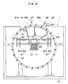
- a filter cloth 20 is wound around the above-mentioned annular stays 17a, 17b and 17c and the reinforcing ribs 19, with protrusions 21 formed at its middle and side edge portions thereof fitted in the grooves 18a, 18b and 18c, respectively, as shown in Figs. 1 and 3.
- a blind plate 14c arranged at a position on the circumference of the filtration drum 14, extends longitudinally between the opposite annular stays 17a and 17c and is secured thereto.
- Paired fastener elements 20a and 20b for example, one composed of a numerous looped engaging element group and the other composed of a numerous mushroom-like engaging element group, are sewed to the obverse surface of one end edge of the filter cloth and to the reverse surface of the other end edge of the same.
- the fastener elements 20a and 20b are overlapped on the outer surface of the blind plate 14c to temporarily fasten the filter cloth 20.
- a press plate 14d is pressed against the blind plate 14c with the end edges of the filter cloth 20 interposed therebetween, and the plate 14d and the end edges of the cloth 20 are fixed to the drum 14 by means of bolts 14e and nuts 14f.
- a flexible flat belt 22a of urethane resin is heat-fused or bonded by an adhesive to each of those outer surface portions of the filter cloth 20 which surround the annular stays 17a, 17b and 17c.
- An annular metal band 23a is wound around each flat belt 22a, such that as the bands 23a are tightened, the filter cloth 20 is securely fastened to the annular stays 17a, 17b and 17c.
- the naps each have a length enough to skip 2 to 6 stitches of the weft.
- the naps having such length can lie on the surface of the base material and form an excellent filter layer with 100 to 40000 naps present per millimeter.
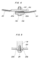
- the collecting water is stored in the bulged portion of the filter cloth 20, as shown in Fig. 16.
- the collecting water flushed from the nozzles 25a does not directly strike against the filter cloth 20 but applies a force to the stored water, thereby promoting the passing of the collecting water through the filter cloth.
Landscapes
- Chemical & Material Sciences (AREA)
- Chemical Kinetics & Catalysis (AREA)
- Filtration Of Liquid (AREA)
- Filtering Materials (AREA)
Claims (13)
- Fest-Flüssig-Trennvorrichtung mit einer Filtertrommel (14), welche eine rotierbare Trommel, die durch mehrere, kreisförmige, parallel zueinander angeordnete Streben (17) und durch mehrere Verstärkungsrippen (19) gebildet wird, welche horizontal angeordnet sind und die kreisförmigen Streben (17) miteinander verbinden, und einem Filterstoff (20), der um die rotierbare Trommel (14) herum befestigt ist, wobei eine Fest-Flüssig-Mischung in die Filtertrommel (14) eingebracht und durch den Filterstoff (20) gedrückt wird, so daß Festkörper aus der Fest-Flüssig-Mischung während des Drehens der Filtertrommel (14) abgeschieden werden, dadurch gekennzeichnet,
daß der Filterstoff (20) ein Basismaterial aufweist, welches eine dem Inneren der Filtertrommel (14) zugewandte Oberfläche aufweist,
daß die Oberfläche des Basismaterials mit einer aufgerauhten Filterschicht bedeckt ist, welche aus einer Vielzahl von Fasern mit einem Durchmesser von 0,1 bis 10 »m gebildet ist,
daß der Filterstoff einen Dehnungskoeffizient Ts von nicht kleiner als 1,0 % in Wicklungsrichtung aufweist, welcher durch die folgende Formel festgelegt ist:

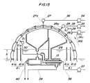
wobei X den Abstand zwischen zwei Punkten auf einem Teststoffstück darstellt, welcher nach dem Aufbringen einer Last von 117,68 N (12 kgf) auf das Teststoffstück für 90 Minuten gemessen wird, wobei das Teststück aus dem Filterstoff ausgeschnitten wird und einen Meßabschnitt mit 250 mm Länge und 30 mm Breite aufweist, und wobei die beiden Punkte zuvor mit einer auf das Teststück aufgebrachten anfänglichen Last von 0,98 N (100 gf) und mit einem 200 mm dazwischenliegenden Abstand beliebig auf dem Meßabschnitt markiert werden. - Vorrichtung nach Anspruch 1, dadurch gekennzeichnet, daß eine erste Sprüheinrichtung (25) außerhalb der Filtertrommel (14) in einer einem Außenumfang des Filterstoffes (20) zugewandten Ausrichtung für das Aufsprühen einer Sammelflüssigkeit auf den Filterstoff (20) angeordnet ist, so daß durch den Filterstoff (20) aufgefangene Festkörper gesammelt werden und daß eine Sammelbehältereinrichtung (29, 30) innerhalb der Filtertrommel (14) zum Sammeln von Festkörpern angeordnet ist, welche durch die Sammelflüssigkeit herausgespült werden.
- Vorrichtung nach Anspruch 1 oder 2, dadurch gekennzeichnet, daß eine zweite Sprüheinrichtung (31) innerhalb der Filtertrommel (14) in einer dem Innenumfang des Filterstoffes (20) zugewandten Ausrichtung für das Aufsprühen einer Waschflüssigkeit auf den Filterstoff (20) angeordnet ist, so daß Festkörper, welche an den Fasern der aufgerauhten Filterschicht anhaften, heraus-gespült werden.
- Vorrichtung nach einem der Ansprüche 1 bis 3, dadurch gekennzeichnet, daß das Basismaterial ein Gewebematerial mit einem Einschlag, welcher sich entlang einer Rotationsachse der rotierbaren Trommel erstreckt und eine Wicklung, welche in Umfangsrichtung der drehbaren Trommel verläuft, umfaßt und daß die Fasern, welche die aufgerauhte Filterschicht bilden, hauptsächlich durch Aufrauhen des Einschlages in einer Richtung, in welcher sich die Wicklung erstreckt, gebildet werden.
- Vorrichtung nach Anspruch 4, dadurch gekennzeichnet, daß mindestens der Einschlag des Gewebematerials Polyesterfasern aufweist.
- Vorrichtung nach einem der Ansprüche 1 bis 5, dadurch gekennzeichnet, daß die erste Sprüheinrichtung (25) von einem Oberteil der Filtertrommel (14) auf der stromaufwärtsliegenden Seite mit Bezug auf die Rotationsrichtung der Filtertrommel (14) beabstandet ist.
- Vorrichtung nach einem der Ansprüche 1 bis 6, dadurch gekennzeichnet, daß die zweite Sprüheinrichtung (31) von einem Oberteil der Filtertrommel (14) auf der stromabwärtsliegenden Seite mit Bezug auf die Rotationsrichtung der Filtertrommel (14) beabstandet ist.
- Vorrichtung nach einem der Ansprüche 1 bis 7, gekennzeichnet durch eine dritte Sprüheinrichtung (27), welche außerhalb der Filtertrommel (14) in einer zugewandten Ausrichtung zu einer Außenumfangsfläche des Filterstoffes (20) für das Sprühen von Chemikalien in Richtung des Filterstoff (20) angeordnet ist, so daß der Filterstoff (20) gewaschen wird.
- Vorrichtung nach einem der Ansprüche 1 bis 8, gekennzeichnet durch eine Spanneinrichtung (23a), welche um einen Außenumfang der kreisförmigen Strebe (17) zum sicheren Befestigen des Filterstoffes (20) an der kreisförmigen Strebe (17) gewickelt ist, und durch eine riemenartige Presseinrichtung (23b), welche entlang einem Außenumfang der Verstärkungsrippen (19) für das Anpressen des Filterstoffes (20) gegen die Verstärkungsrippe (19) und für dessen Befestigen an der Verstärkungsrippe (19), verläuft.
- Vorrichtung nach Anspruch 9, dadurch gekennzeichnet, daß ein erstes flexibles Element (22a) zwischen der Spanneinrichtung (23a) und dem Filterstoff (20) angeordnet ist, und daß ein zweites flexibles Element (22b) zwischen der Presseinrichtung (23b) und der Verstärkungsrippe (19) angeordnet ist.
- Vorrichtung nach einem der Ansprüche 1 bis 10, gekennzeichnet durch eine Ablenkeinrichtung (41), welche innerhalb der Filtertrommel (14) für das Dämpfen von Wellen angeordnet ist, welche an der Oberfläche der Fest-Flüssig-Mischung erzeugt werden.
- Vorrichtung nach Anspruch 11, dadurch gekennzeichnet, daß die Ablenkeinrichtung (41) ein Plattenelement umfaßt, welches entlang einer Rotationsachse der Filtertrommel (14) verläuft und einen oberen Rand, der über die Oberfläche der Fest-Flüssig-Mischung in der Filtertrommel (14) vorsteht und einen unteren Rand aufweist, welcher in die Mischung in der Filtertrommel (14) eintaucht.
- Vorrichtung nach Anspruch 11 oder 12, dadurch gekennzeichnet, daß die Ablenkeinrichtung (41) vertikal in Übereinstimmung mit der Höhe der Oberfläche der Fest-Flüssig-Mischung in der Filtertrommel (14) bewegbar ist.
Priority Applications (5)
| Application Number | Priority Date | Filing Date | Title |
|---|---|---|---|
| EP88114056A EP0357809B1 (de) | 1988-08-29 | 1988-08-29 | Rotierende Filtertrommel für Fest-Flüssig-Trennung |
| CA000575956A CA1330051C (en) | 1988-08-29 | 1988-08-29 | Rotary drum type solid-liquid separation apparatus |
| DE3850254T DE3850254T2 (de) | 1988-08-29 | 1988-08-29 | Rotierende Filtertrommel für Fest-Flüssig-Trennung. |
| US07/239,206 US4869823A (en) | 1988-08-29 | 1988-08-30 | Rotary drum type solid-liquid separation apparatus |
| AU21686/88A AU600166B2 (en) | 1988-08-29 | 1988-08-30 | Rotary drum type solid-liquid separation apparatus |
Applications Claiming Priority (2)
| Application Number | Priority Date | Filing Date | Title |
|---|---|---|---|
| EP88114056A EP0357809B1 (de) | 1988-08-29 | 1988-08-29 | Rotierende Filtertrommel für Fest-Flüssig-Trennung |
| CA000575956A CA1330051C (en) | 1988-08-29 | 1988-08-29 | Rotary drum type solid-liquid separation apparatus |
Publications (2)
| Publication Number | Publication Date |
|---|---|
| EP0357809A1 EP0357809A1 (de) | 1990-03-14 |
| EP0357809B1 true EP0357809B1 (de) | 1994-06-15 |
Family
ID=25672087
Family Applications (1)
| Application Number | Title | Priority Date | Filing Date |
|---|---|---|---|
| EP88114056A Expired - Lifetime EP0357809B1 (de) | 1988-08-29 | 1988-08-29 | Rotierende Filtertrommel für Fest-Flüssig-Trennung |
Country Status (5)
| Country | Link |
|---|---|
| US (1) | US4869823A (de) |
| EP (1) | EP0357809B1 (de) |
| AU (1) | AU600166B2 (de) |
| CA (1) | CA1330051C (de) |
| DE (1) | DE3850254T2 (de) |
Families Citing this family (28)
| Publication number | Priority date | Publication date | Assignee | Title |
|---|---|---|---|---|
| NZ227050A (en) * | 1988-11-22 | 1992-04-28 | Contra Shear Holdings | Pressure separation apparatus; rotating drum screen with tangential ejection nozzles |
| IT1243121B (it) * | 1990-06-22 | 1994-05-24 | Padovan Snc Di Giorgio Mario E | Ciclo di filtrazione per liquidi contenenti solidi in sospensione e filtro rotativo adatto a realizzare tale ciclo di filtrazione. |
| US5139670A (en) * | 1991-04-22 | 1992-08-18 | Gene Hirs | Rotating drum filter |
| US5182008A (en) * | 1991-04-24 | 1993-01-26 | Shelstad Richard J | Filtration assembly |
| EP0707509B1 (de) * | 1993-07-06 | 1998-09-30 | Nordic Water Products Aktiebolag | Vorrichtung zur filtration von teilchenenthaltenden flüssigkeiten |
| EP0848979A4 (de) * | 1996-05-31 | 1999-01-13 | Toray Industries | Filtertuch und filter |
| US5894936A (en) * | 1997-07-30 | 1999-04-20 | Sanders Brine Shrimp Company, Inc, | Drum separator for brine shrimp eggs |
| US6101738A (en) * | 1998-07-27 | 2000-08-15 | Gleason; Gary | Sludge dewatering system and method |
| US6186340B1 (en) * | 1998-10-14 | 2001-02-13 | Gene Hirs | Cylindrical drum filter having two parallel circular circumferentially spaced support rods |
| FI107517B (fi) * | 1999-04-21 | 2001-08-31 | Tamfelt Oyj Abp | Menetelmä kutisteviiran valmistamiseksi ja kutisteviira |
| US6419094B1 (en) * | 2000-02-09 | 2002-07-16 | Lyco Manufacturing, Inc. | Fixed sequential sprayer for a cylindrical wastewater screen |
| EP1475138A1 (de) * | 2003-05-07 | 2004-11-10 | Marzio Vidali | Filterapparatur für Fluide mit partikelförmigen Abfallstoffen |
| DE102004045445A1 (de) * | 2004-09-18 | 2006-03-23 | Premark Feg L.L.C., Wilmington | Geschirrspülanlage |
| TWM301696U (en) * | 2006-02-27 | 2006-12-01 | Fisheries Res Inst | Automation filtration apparatus for aquatic organism |
| US8734641B2 (en) | 2010-09-08 | 2014-05-27 | Anthony Collins | Tertiary wastewater filtration using inclined filter media and internal reverse flow backwashing of filter disks |
| CN102716610B (zh) * | 2012-06-27 | 2014-06-11 | 江苏赛德力制药机械制造有限公司 | 一种加压转鼓过滤机 |
| US20140124461A1 (en) * | 2012-11-07 | 2014-05-08 | Veolia Water Solutions & Technologies Support | Process for Inhibiting Biological Growth On a Gravity Fed Disc Filter |
| CN103230694B (zh) * | 2013-05-10 | 2015-04-01 | 河北科技大学 | 用于花草汁液提取的固液分离一体机 |
| US10076716B2 (en) * | 2014-08-22 | 2018-09-18 | Gl&V Usa Inc. | Pinned fly ring for rotary drum washer and method of manufacture |
| DE102014016453B4 (de) | 2014-11-06 | 2018-08-23 | Lemmermeyer Gmbh & Co. Kg | Filtersystem, seine Verwendung sowie ein Verfahren zur Filtration von einer Lauge |
| GB201516253D0 (en) * | 2015-09-14 | 2015-10-28 | Univ Montfort | Rotating contactor reactor |
| US11529573B2 (en) | 2019-04-23 | 2022-12-20 | Greatpyr Resources Llc | Systems and processes employing wet/dry suction filter |
| CN113471642B (zh) * | 2021-04-02 | 2023-08-15 | 浙江南都电源动力股份有限公司 | 一种负极防护组件及负极防护电池及负极防护方法 |
| US12377372B2 (en) | 2021-06-08 | 2025-08-05 | Greatpyr Resources Llc | Apparatus, systems, and processes employing wet/dry suction filter with chicaned suction head |
| US12544693B2 (en) * | 2021-09-10 | 2026-02-10 | Algaecore Technologies Ltd | Rotary drum filtering machine for algae filtration |
| US12246272B2 (en) | 2021-11-04 | 2025-03-11 | Thomas E. Frankel | Wastewater filters and wastewater filtration systems specifically adapted for their use |
| CN114344989B (zh) * | 2022-01-06 | 2023-05-05 | 陕西理工大学 | 一种生活垃圾固液分离预处理设备 |
| CN118892918B (zh) * | 2024-10-08 | 2025-01-17 | 苏州盛天力离心机制造有限公司 | 轻质物料立式离心机用压缩上出料装置及离心机 |
Family Cites Families (18)
| Publication number | Priority date | Publication date | Assignee | Title |
|---|---|---|---|---|
| US1833315A (en) * | 1923-12-21 | 1931-11-24 | Harry H Burhans | Filtering medium |
| US1870442A (en) * | 1929-09-10 | 1932-08-09 | Dorr Co Inc | Application of liquid to filter cakes |
| US1917696A (en) * | 1931-06-12 | 1933-07-11 | Budke Carl | Continuous pressure filter |
| FR895408A (fr) * | 1942-05-20 | 1945-01-24 | Domaniale Mijn Mij N V | Tamis à tambour rotatif particulièrement destiné à la séparation des boues provenant du traitement de la houille |
| BE526519A (de) * | 1953-02-21 | |||
| FR1404009A (fr) * | 1964-06-22 | 1965-06-25 | Appareil pour la filtration de liquides | |
| GB1008617A (en) * | 1964-06-22 | 1965-10-27 | Ivar Wallquist | Apparatus for filtration of liquids |
| JPS4980664A (de) * | 1972-11-01 | 1974-08-03 | ||
| US3979289A (en) * | 1972-11-08 | 1976-09-07 | Water Pollution Control Corporation | Filtration method |
| US4198299A (en) * | 1973-12-26 | 1980-04-15 | Water Pollution Control Corporation | Microscreen method and apparatus |
| DE2505565A1 (de) * | 1975-02-10 | 1976-08-26 | Zell I W J Krueckels Maschf | Verfahren zum sieben einer fluessigkeit, und vorrichtung zum durchfuehren eines solchen verfahrens |
| US4038187A (en) * | 1976-02-03 | 1977-07-26 | Envirex Inc. | Microscreen drum |
| GB2072522A (en) * | 1980-03-25 | 1981-10-07 | Coal Industry Patents Ltd | Thickener |
| JPS58207917A (ja) * | 1982-05-31 | 1983-12-03 | Toray Ind Inc | 転写型脱水機用濾布 |
| HU184550B (en) * | 1982-06-11 | 1984-09-28 | Dunai Vasmu | Universal water treating apparatus of continuous regeneration |
| JPS59115720A (ja) * | 1982-12-24 | 1984-07-04 | Toray Ind Inc | 固液分離用濾布 |
| JPS6135886A (ja) * | 1984-07-27 | 1986-02-20 | Nippon Oil & Fats Co Ltd | ポリブチレンテレフタレ−ト樹脂の塗装方法 |
| DE3475880D1 (en) * | 1984-08-27 | 1989-02-09 | Toray Industries | Solid-liquid separating apparatus |
-
1988
- 1988-08-29 DE DE3850254T patent/DE3850254T2/de not_active Expired - Fee Related
- 1988-08-29 EP EP88114056A patent/EP0357809B1/de not_active Expired - Lifetime
- 1988-08-29 CA CA000575956A patent/CA1330051C/en not_active Expired - Fee Related
- 1988-08-30 AU AU21686/88A patent/AU600166B2/en not_active Ceased
- 1988-08-30 US US07/239,206 patent/US4869823A/en not_active Expired - Lifetime
Also Published As
| Publication number | Publication date |
|---|---|
| EP0357809A1 (de) | 1990-03-14 |
| AU2168688A (en) | 1990-04-26 |
| US4869823A (en) | 1989-09-26 |
| DE3850254T2 (de) | 1994-09-29 |
| CA1330051C (en) | 1994-06-07 |
| AU600166B2 (en) | 1990-08-02 |
| DE3850254D1 (de) | 1994-07-21 |
Similar Documents
| Publication | Publication Date | Title |
|---|---|---|
| EP0357809B1 (de) | Rotierende Filtertrommel für Fest-Flüssig-Trennung | |
| EP0191102B1 (de) | Fest-flüssig-trennvorrichtung | |
| KR20010072406A (ko) | 고액 분리용 막 어셈블리, 그의 세척 방법, 및 세제 | |
| CN1079685C (zh) | 滤布和过滤机 | |
| JPH0717366Y2 (ja) | 回転ドラム型固液分離装置 | |
| JP2000176481A (ja) | 濾過装置 | |
| JPH0696081B2 (ja) | 回転ドラム型固液分離装置 | |
| JPS61274719A (ja) | 固液分離装置 | |
| JPH046807Y2 (de) | ||
| CN220723775U (zh) | 曝气生物滤池滤料拦截装置 | |
| JP3985945B2 (ja) | 毛管現象を利用した水処理方法およびその装置 | |
| JP3607794B2 (ja) | 汚水濾過装置 | |
| JP3060821B2 (ja) | 固液分離装置および固液分離方法 | |
| JPH0924211A (ja) | 汚水の濾過装置 | |
| JPS6048107A (ja) | 固液分離装置 | |
| JPH09271613A (ja) | 汚水の濾過装置 | |
| JPH042285B2 (de) | ||
| JPH0118768B2 (de) | ||
| KR100539426B1 (ko) | 다공성판의 착탈이 가능한 폴리머 필터 엘리먼트 | |
| JPS6363312B2 (de) | ||
| JPS646895Y2 (de) | ||
| JPH0113528Y2 (de) | ||
| JPS6121710A (ja) | 固液分離装置 | |
| JPS646897Y2 (de) | ||
| JPS646894Y2 (de) |
Legal Events
| Date | Code | Title | Description |
|---|---|---|---|
| PUAI | Public reference made under article 153(3) epc to a published international application that has entered the european phase |
Free format text: ORIGINAL CODE: 0009012 |
|
| AK | Designated contracting states |
Kind code of ref document: A1 Designated state(s): DE FR GB IT NL |
|
| 17P | Request for examination filed |
Effective date: 19900905 |
|
| 17Q | First examination report despatched |
Effective date: 19910528 |
|
| GRAA | (expected) grant |
Free format text: ORIGINAL CODE: 0009210 |
|
| AK | Designated contracting states |
Kind code of ref document: B1 Designated state(s): DE FR GB IT NL |
|
| ITF | It: translation for a ep patent filed | ||
| REF | Corresponds to: |
Ref document number: 3850254 Country of ref document: DE Date of ref document: 19940721 |
|
| ET | Fr: translation filed | ||
| PLBE | No opposition filed within time limit |
Free format text: ORIGINAL CODE: 0009261 |
|
| STAA | Information on the status of an ep patent application or granted ep patent |
Free format text: STATUS: NO OPPOSITION FILED WITHIN TIME LIMIT |
|
| 26N | No opposition filed | ||
| PGFP | Annual fee paid to national office [announced via postgrant information from national office to epo] |
Ref country code: FR Payment date: 20010810 Year of fee payment: 14 |
|
| PGFP | Annual fee paid to national office [announced via postgrant information from national office to epo] |
Ref country code: DE Payment date: 20010820 Year of fee payment: 14 |
|
| PGFP | Annual fee paid to national office [announced via postgrant information from national office to epo] |
Ref country code: NL Payment date: 20010830 Year of fee payment: 14 Ref country code: GB Payment date: 20010830 Year of fee payment: 14 |
|
| REG | Reference to a national code |
Ref country code: GB Ref legal event code: IF02 |
|
| PG25 | Lapsed in a contracting state [announced via postgrant information from national office to epo] |
Ref country code: GB Free format text: LAPSE BECAUSE OF NON-PAYMENT OF DUE FEES Effective date: 20020829 |
|
| PG25 | Lapsed in a contracting state [announced via postgrant information from national office to epo] |
Ref country code: NL Free format text: LAPSE BECAUSE OF NON-PAYMENT OF DUE FEES Effective date: 20030301 Ref country code: DE Free format text: LAPSE BECAUSE OF NON-PAYMENT OF DUE FEES Effective date: 20030301 |
|
| GBPC | Gb: european patent ceased through non-payment of renewal fee |
Effective date: 20020829 |
|
| PG25 | Lapsed in a contracting state [announced via postgrant information from national office to epo] |
Ref country code: FR Free format text: LAPSE BECAUSE OF NON-PAYMENT OF DUE FEES Effective date: 20030430 |
|
| NLV4 | Nl: lapsed or anulled due to non-payment of the annual fee |
Effective date: 20030301 |
|
| REG | Reference to a national code |
Ref country code: FR Ref legal event code: ST |
|
| PG25 | Lapsed in a contracting state [announced via postgrant information from national office to epo] |
Ref country code: IT Free format text: LAPSE BECAUSE OF NON-PAYMENT OF DUE FEES Effective date: 20050829 |