EP0357944A1 - Installation de radiodiagnostic dentaire pour réaliser une tomographie panoramique de la mâchoire d'un patient - Google Patents
Installation de radiodiagnostic dentaire pour réaliser une tomographie panoramique de la mâchoire d'un patient Download PDFInfo
- Publication number
- EP0357944A1 EP0357944A1 EP89114016A EP89114016A EP0357944A1 EP 0357944 A1 EP0357944 A1 EP 0357944A1 EP 89114016 A EP89114016 A EP 89114016A EP 89114016 A EP89114016 A EP 89114016A EP 0357944 A1 EP0357944 A1 EP 0357944A1
- Authority
- EP
- European Patent Office
- Prior art keywords
- image
- ccd
- clock
- ccd sensor
- sensor
- Prior art date
- Legal status (The legal status is an assumption and is not a legal conclusion. Google has not performed a legal analysis and makes no representation as to the accuracy of the status listed.)
- Granted
Links
- 238000009434 installation Methods 0.000 title abstract 2
- 238000003325 tomography Methods 0.000 title 1
- 230000005855 radiation Effects 0.000 claims abstract description 8
- 238000000034 method Methods 0.000 claims description 7
- 230000008569 process Effects 0.000 claims description 6
- 238000005516 engineering process Methods 0.000 claims description 5
- 239000000758 substrate Substances 0.000 claims description 3
- 239000010410 layer Substances 0.000 description 31
- 238000007781 pre-processing Methods 0.000 description 8
- 238000010586 diagram Methods 0.000 description 6
- 238000003384 imaging method Methods 0.000 description 5
- 230000010354 integration Effects 0.000 description 4
- 230000000903 blocking effect Effects 0.000 description 3
- 230000004913 activation Effects 0.000 description 2
- 230000008901 benefit Effects 0.000 description 2
- 230000005540 biological transmission Effects 0.000 description 2
- 238000007599 discharging Methods 0.000 description 2
- 238000000926 separation method Methods 0.000 description 2
- 230000015572 biosynthetic process Effects 0.000 description 1
- 230000008859 change Effects 0.000 description 1
- 238000010276 construction Methods 0.000 description 1
- 239000000835 fiber Substances 0.000 description 1
- 238000002161 passivation Methods 0.000 description 1
- 230000000149 penetrating effect Effects 0.000 description 1
- 238000002360 preparation method Methods 0.000 description 1
- 230000009467 reduction Effects 0.000 description 1
- 239000002356 single layer Substances 0.000 description 1
Images


Classifications
-
- A—HUMAN NECESSITIES
- A61—MEDICAL OR VETERINARY SCIENCE; HYGIENE
- A61B—DIAGNOSIS; SURGERY; IDENTIFICATION
- A61B6/00—Apparatus or devices for radiation diagnosis; Apparatus or devices for radiation diagnosis combined with radiation therapy equipment
- A61B6/02—Arrangements for diagnosis sequentially in different planes; Stereoscopic radiation diagnosis
- A61B6/03—Computed tomography [CT]
- A61B6/032—Transmission computed tomography [CT]
-
- A—HUMAN NECESSITIES
- A61—MEDICAL OR VETERINARY SCIENCE; HYGIENE
- A61B—DIAGNOSIS; SURGERY; IDENTIFICATION
- A61B6/00—Apparatus or devices for radiation diagnosis; Apparatus or devices for radiation diagnosis combined with radiation therapy equipment
- A61B6/44—Constructional features of apparatus for radiation diagnosis
- A61B6/4429—Constructional features of apparatus for radiation diagnosis related to the mounting of source units and detector units
- A61B6/4435—Constructional features of apparatus for radiation diagnosis related to the mounting of source units and detector units the source unit and the detector unit being coupled by a rigid structure
-
- A—HUMAN NECESSITIES
- A61—MEDICAL OR VETERINARY SCIENCE; HYGIENE
- A61B—DIAGNOSIS; SURGERY; IDENTIFICATION
- A61B6/00—Apparatus or devices for radiation diagnosis; Apparatus or devices for radiation diagnosis combined with radiation therapy equipment
- A61B6/50—Apparatus or devices for radiation diagnosis; Apparatus or devices for radiation diagnosis combined with radiation therapy equipment specially adapted for specific body parts; specially adapted for specific clinical applications
- A61B6/51—Apparatus or devices for radiation diagnosis; Apparatus or devices for radiation diagnosis combined with radiation therapy equipment specially adapted for specific body parts; specially adapted for specific clinical applications for dentistry
Definitions
- the invention relates to an X-ray diagnostic device of the type described in German patent application P 37 04 858.
- a stationary GGD sensor arrangement is provided, which is controlled with the aid of a clock generator so that the charge images obtained are clocked into a storage zone at the same speed and then be clocked out line by line again using a shift register with which an X-ray film is moved relative to the secondary gap in the conventional recording technique.
- the clock frequency is according to the relationship selected, where v represents the film speed, n x the image ratio of the image-transmitting system and a the line spacing.
- the invention specified in claim 1 is based on the object of specifying a possibility for an X-ray diagnostic device of the aforementioned type to be able to simultaneously detect several slices during an exposure, the slices being to be freely definable within certain limits. There should also be a possibility to be able to take meaningful recordings of layers that are not in one plane, but rather to take a curved course, for example of teeth lying obliquely in the jaw.
- each layer can be freely defined within certain limits.
- the different control need not be carried out uniformly via the CCD sensor; it can advantageously be concentrated on certain surface areas of the CCD sensor or the sensor arrangement.
- the clock frequencies of groups of gaps can be divided so that the recorded layer assumes a curved course, so that teeth lying obliquely in the jaw can also be depicted sharply.
- the depth of focus of the layer created can be varied by changing the image zone width of the sensor by passivating a few lines of the sensor.
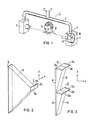
- FIG. 1 shows a greatly simplified perspective illustration of the essential parts of a dental X-ray diagnostic device for the creation of panoramic slice images.
- the diagnostic device contains a rotating unit 1 which can be pivoted about a vertical axis, consisting of a support arm 2, at one end of which an X-ray emitter 3 and at the other end of which a radiation recording unit 4 are held.
- the rotating unit 1 is adjustable in a known manner relative to the patient's head 5 in such a way that an overview of the entire jaw 6 of a patient can be created.
- the adjustment devices and movement sequences required for this purpose, which the rotary unit carries out, are well known and therefore do not need to be explained in detail anymore.
- the radiation receiving unit 4 contains, in a known manner, an aperture 7 with a secondary slit 8 with dimensions of, for example, 5 ⁇ 125 mm.
- the secondary slit 8 is followed by means for converting the X-rays into visible rays.
- a scintillator layer 9 with the dimensions of the secondary gap is provided in the secondary gap level (FIG. 2).
- the scintillator layer 9 is followed by an image transmission element 10 in the form of a fiber optic, which reduces the format of the secondary gap from 5 ⁇ 125 mm to the format of the image zone of a CCD sensor 11 with the dimensions of, for example, 8 ⁇ 8 mm.
- the CCD sensor 11 is of a type in which the memory and image zones (11a, 11b) are arranged spatially separated within the chip and in which the shift register 11c is coupled to the CCD memory zone 11b.
- a CCD type can also be used in which the image and memory zone are arranged together within a chip.
- the following description assumes that the entire secondary gap 8 is imaged on the surface of a single CCD sensor, as shown in FIG. 2. From today's point of view, however, it is advisable to provide several CCD sensors in order to cover the secondary gap 8, as is shown in FIG. 3. According to this illustration, two CCD sensors 12 and 13, which are arranged approximately at right angles to the secondary gap plane and, as transmission elements, two fiber-optic elements 14, 15 are provided for imaging the secondary gap 8.
- the individual CCD sensors are of the same type as in FIG. 2, that is to say with a memory zone spatially separated from the image zone and a subsequent shift register. As mentioned above, these can advantageously also be designed without a storage zone.
- the signal processing is explained using the basic circuit diagram according to FIG. 4.
- the signals obtained from the detector arrangement (CCD sensor / sensors) are then sent to an A / D converter 16 after signal processing, to which a digital image processing system with a preprocessing unit 17, an image memory 18, an image readout unit 19, a monitor 20 and connect a computer 21.
- a clock generator which will be explained in more detail later, is designated with which the CCD sensors are controlled.
- K-shift registers, K-signal preparations and KA / D converters can also be used corresponding to the K groups of columns.
- the image information present at the output of a shift register 11c of the CCD sensor 11 is digitized in the associated A / D converter and then either entered directly into the image memory 18 or, after preprocessing, stored in the unit 17 in the image memory 18.
- the computer 21 issues the necessary control or readout commands.
- the direct input of the signals received by the A / D converter into the image memory 18 is advantageous if the latter has a correspondingly large capacity at a reasonable cost or construction volume.
- the data is initially only saved during one revolution of the rotating unit and is only processed after the recording has been completed, i.e. after the emitter has rotated around the patient's head, i.e. added at the speed corresponding to a film recording.
- this solution has the advantage that it is possible to display any number of layers.
- This preprocessing unit contains a buffer and an arithmetic processor, as a result of which the digital data from the A / D converter are added in a timely manner in accordance with a control command from the computer 21, that is to say are put together in such a way that a layer image of a desired layer position is produced.
- the resulting processed data are then placed in the image memory 18.
- the layer position is determined by interposing such a preprocessing unit, ie the layer position can no longer be changed within certain limits, in contrast to the aforementioned alternative arrangement without a preprocessing unit, where the image data are only combined to form a layer image after being recorded.
- a compromise can also be provided between the two possibilities, according to which several adjacent image columns are added in time in the preprocessing unit 17 before being stored in the image memory, and these sum columns are added to an image column after being stored.
- the patient is irradiated by a rectangular, slit-shaped beam bounded by a primary diaphragm located in the X-ray emitter 3.
- the beam strikes the secondary slit 8 of the secondary aperture 7 and then strikes the scintillator layer 9, where it is converted into visible beams, which are finally picked up by the CCD sensor.
- the signals recorded by the CCD sensor are proportional to the radiation intensity of the X-rays penetrating the patient's head.
- an X-ray film to be exposed is drawn past at a certain speed, the selected speed influencing the position of the tomographic layer, ie the tomographic layer can be changed by changing the film speed.
- the signals generated at the detector as explained in more detail below, processed in a certain way into a panorama slice image that can be reproduced on a monitor.
- the relationship between the secondary gap and the image zone of the CCD sensor is first explained. It is assumed that the secondary gap 8 is imaged on the image zone of one or more CCD sensors.
- the imaging ratio in the x direction, ie perpendicular to the longitudinal extension of the secondary gap 8, is l: n x and l: n y in the y direction.
- n x 1 in the case under consideration.
- the imaging scale n y can be between 1 and about 20 in the longitudinal direction of the gap.
- 1 to n light pixels in the secondary gap correspond to 1 to n charge pixels in the CCD sensor.
- the image is transported from the image zone 11a to the memory zone 11b and from there is read out via the shift register 11c and input into the A / D converter.
- the image integration time is approximately 20 ms.
- the image is then clocked into the storage zone. This requires as many clock cycles as the CCD sensor has rows.
- Using a CCD type with 300 lines and a clock of The image zone is emptied after approx. 0.6 ms after 2 ⁇ s and can then immediately take a new image. While in conventional layer recording technology the film is moved past the secondary gap at a certain speed, i.e.
- the image information located at the secondary gap is integrated on the image over a certain period of time, according to the invention this integration of the image information is electronically imitated by the
- the resulting light image on the scintillator is imaged on the surface of the CCD sensor and the resulting charge image is clocked in a certain cycle sequence from the image zone into the storage zone and is then clocked line by line via the shift register.
- the clock sequence is chosen so that the charge pattern, based on the secondary gap plane, has the same speed in the x-direction that a film would have with conventional layer recording technology.
- the clock frequency determined has the following relationship to the equivalent speed (v) of a film: where f clock indicates the number of lines per second and (n x ⁇ a) the CCD line spacing, based on the secondary column level. With a typical film speed of 30 mm / s and a line spacing of 20 ⁇ m and based on an imaging ratio of 1: 1 in the x direction, a clock frequency of 1,500 Hz would result.
- the presence of a memory zone in the CCD sensor is not absolutely necessary; it can rather be advantageous to shift the charges from the image zone line by line directly into the shift register and to clock them out there. This avoids unnecessary charge transport.
- the CCD sensor 11 is divided into columns b1 to b m .
- a charge image is generated which corresponds to an exposed area on a conventionally irradiated X-ray film.
- the charges are shifted in columns from one CCD line to the next and clocked out into the storage zone 11b or directly into a shift register 1c.
- the speed at which this process takes place is determined by the shifting clock frequency.
- the product a ⁇ f corresponds to the film speed with conventional X-ray imaging technology.
- some of the CCD columns b1 to b m are driven with different clock frequencies t1 to t k .
- Each clock frequency corresponds to a recording layer.
- the control can be evenly distributed via the CCD sensor; However, it is advantageous to focus the different activation of the columns on specific surface areas of the CCD sensor element, or when certain CCD sensor elements cover a secondary gap, on specific areas of the secondary gap.
- Such a concentration on certain surface areas is appropriate, for example, if several layers are to be captured in some image areas and a reduction in image resolution can be accepted, while in other image areas a single layer is sufficient.
- FIG. 7 shows such a concentration on the upper surface section of the CCD sensor.
- the columns b2, b4, b6, b8 and b10, the clock frequency t2, the columns b3, b7 and b11 and the clock frequency t3, the columns b1, b5, b9 and b12 and then each further column are driven with the clock frequency t1 .
- three different layers corresponding to the clock frequencies t 1, t 2 and t 3 can thus be detected in the upper image section, while only one layer, namely the layer corresponding to the clock frequency t 3, is imaged in the lower image section.
- each column has a corresponding clock input, which, according to FIG. 4, is connected to the clock generator 22.
- the clock frequencies t 1 to t k can advantageously be divided so that the jaw is not a flat, but a curved layer.
- all the desired layers can be represented independently of one another, further intermediate layers can be calculated and also several layers can be combined to form a layer with a larger depth of field.
- FIG. 8 shows a basic illustration of the arrangement of the photosensitive cells and electrodes of a CCD sensor.
- each pixel of a CCD sensor consists of four areas -
- the photosensitive cells a11, a12, a13 ... a 1n which are shown in the illustration for n lines in each column b1, b2 ... b m with each other -
- the potential trenches d1, d2 ... d m into which the charges are "suctioned" after decoupling and passed to the ground (substrate of the CCD sensor) and -
- the separation zones e1, e2 ... e n between the individual columns b1, b2 ... b m The separation zones e1, e2 ... e n between the individual columns b1, b2 ... b m .
- the four areas are at four different voltage potentials (U), the arrowhead pointing to a higher voltage potential, as indicated by the arrow.
- the charges flow line by line (lines 1, 2 ... n) from a11, a12 ... a 1n to the image storage zone or, if one does not exist, directly to the shift register.
- the distribution of the voltage potentials for these four areas is shown in FIG. 9 in this state.
- the blocking electrode activated i.e. if a signal is set there via a corresponding connection, all charges fall from a 11 to a13 in the potential trench d1, whereby these charges are deleted. This state is shown in simplified form in FIG. 10.
- the charge transport at a certain point in the picture plane is interrupted and, as already mentioned above, the depth of field can be varied.
Landscapes
- Health & Medical Sciences (AREA)
- Life Sciences & Earth Sciences (AREA)
- Engineering & Computer Science (AREA)
- Medical Informatics (AREA)
- Heart & Thoracic Surgery (AREA)
- Animal Behavior & Ethology (AREA)
- Biophysics (AREA)
- Nuclear Medicine, Radiotherapy & Molecular Imaging (AREA)
- Optics & Photonics (AREA)
- Pathology (AREA)
- Radiology & Medical Imaging (AREA)
- Biomedical Technology (AREA)
- Physics & Mathematics (AREA)
- Molecular Biology (AREA)
- Surgery (AREA)
- High Energy & Nuclear Physics (AREA)
- General Health & Medical Sciences (AREA)
- Public Health (AREA)
- Veterinary Medicine (AREA)
- Pulmonology (AREA)
- Theoretical Computer Science (AREA)
- Dentistry (AREA)
- Oral & Maxillofacial Surgery (AREA)
- Apparatus For Radiation Diagnosis (AREA)
- Closed-Circuit Television Systems (AREA)
Applications Claiming Priority (2)
| Application Number | Priority Date | Filing Date | Title |
|---|---|---|---|
| DE3827474 | 1988-08-12 | ||
| DE3827474 | 1988-08-12 |
Publications (2)
| Publication Number | Publication Date |
|---|---|
| EP0357944A1 true EP0357944A1 (fr) | 1990-03-14 |
| EP0357944B1 EP0357944B1 (fr) | 1993-09-22 |
Family
ID=6360767
Family Applications (1)
| Application Number | Title | Priority Date | Filing Date |
|---|---|---|---|
| EP89114016A Expired - Lifetime EP0357944B1 (fr) | 1988-08-12 | 1989-07-28 | Installation de radiodiagnostic dentaire pour réaliser une tomographie panoramique de la mâchoire d'un patient |
Country Status (4)
| Country | Link |
|---|---|
| US (1) | US4995062A (fr) |
| EP (1) | EP0357944B1 (fr) |
| JP (1) | JP2911490B2 (fr) |
| DE (1) | DE58905668D1 (fr) |
Cited By (3)
| Publication number | Priority date | Publication date | Assignee | Title |
|---|---|---|---|---|
| FR2720259A1 (fr) * | 1994-05-31 | 1995-12-01 | Trophy Radiologie | Appareil de radiodiagnostic du type à capteur à transfert de charge. |
| WO1996025880A1 (fr) * | 1995-02-21 | 1996-08-29 | Eev Limited | Systeme d'imagerie panoramique dentaire |
| FR2797760A1 (fr) * | 1999-08-30 | 2001-03-02 | Trophy Radiologie | Procede pour obtenir une image radiographique d'une dent et de son environnement, et dispositifs permettant de mettre en oeuvre ce procede |
Families Citing this family (26)
| Publication number | Priority date | Publication date | Assignee | Title |
|---|---|---|---|---|
| US5259013A (en) * | 1991-12-17 | 1993-11-02 | The United States Of America As Represented By The Secretary Of Commerce | Hard x-ray magnification apparatus and method with submicrometer spatial resolution of images in more than one dimension |
| EP0632995B1 (fr) * | 1993-07-06 | 1999-04-21 | Sirona Dental Systems GmbH & Co.KG | Appareil de radiodiagnostic dentaire |
| US5553168A (en) * | 1994-01-21 | 1996-09-03 | Texas Instruments Incorporated | System and method for recognizing visual indicia |
| DE9421296U1 (de) * | 1994-10-17 | 1996-02-22 | Kovacs, Sandor, 81377 München | Röntgenaufnahmegerät |
| JP3291406B2 (ja) * | 1995-02-09 | 2002-06-10 | 株式会社モリタ製作所 | パノラマx線撮影装置 |
| GB9503423D0 (en) * | 1995-02-21 | 1995-04-12 | Eev Ltd | Imaging systems |
| JP3319905B2 (ja) * | 1995-03-24 | 2002-09-03 | 株式会社モリタ製作所 | デジタルx線撮影装置 |
| JP3441578B2 (ja) * | 1995-11-22 | 2003-09-02 | 株式会社モリタ製作所 | 歯科用パノラマx線撮影装置 |
| EP1219147B1 (fr) | 1999-10-08 | 2006-11-08 | Gendex Corporation | Commande automatique de l'exposition pour un appareil de radiographie dentaire panoramique et de cephalographie |
| WO2001058148A1 (fr) | 2000-02-02 | 2001-08-09 | Dentsply International Inc. | Detection automatique de rayons x pour appareil d'imagerie dentaire intraorale par rayons x |
| KR100443135B1 (ko) * | 2001-06-04 | 2004-08-04 | 김도윤 | 의료용 디지털 엑스레이 장치 |
| JP2004536643A (ja) * | 2001-07-25 | 2004-12-09 | デンツプライ インターナショナル インコーポレーテッド | 実時間デジタルx線撮像装置 |
| US7197109B2 (en) | 2002-07-25 | 2007-03-27 | Gendex Corporation | Real-time digital x-ray imaging apparatus |
| US20040184643A1 (en) * | 2003-03-21 | 2004-09-23 | Stantchev Gueorgui H. | Methods and apparatus for imaging |
| US7190834B2 (en) * | 2003-07-22 | 2007-03-13 | Cognex Technology And Investment Corporation | Methods for finding and characterizing a deformed pattern in an image |
| US8295432B2 (en) | 2005-05-02 | 2012-10-23 | Oy Ajat Ltd | Radiation imaging device with irregular rectangular shape and extraoral dental imaging system therefrom |
| US7742560B2 (en) * | 2005-05-02 | 2010-06-22 | Oy Ajat Ltd. | Radiation imaging device with irregular rectangular shape and extraoral dental imaging system therefrom |
| US9332950B2 (en) | 2005-05-02 | 2016-05-10 | Oy Ajat Ltd. | Radiation imaging device with irregular rectangular shape and extraoral dental imaging system therefrom |
| US7676022B2 (en) | 2005-05-02 | 2010-03-09 | Oy Ajat Ltd. | Extra-oral digital panoramic dental x-ray imaging system |
| US7336763B2 (en) | 2005-05-02 | 2008-02-26 | Oy Ajat Ltd | Dental extra-oral x-ray imaging system and method |
| US8433033B2 (en) | 2005-10-21 | 2013-04-30 | Axion Japan Co., Ltd. | Panoramic imaging apparatus |
| JP4746482B2 (ja) * | 2006-05-25 | 2011-08-10 | 株式会社吉田製作所 | 断層面画像生成装置、断層面画像生成方法および断層面画像生成プログラム |
| US7715525B2 (en) * | 2008-03-13 | 2010-05-11 | Oy Ajat Limited | Single sensor multi-functional dental extra-oral x-ray imaging system and method |
| US7715526B2 (en) * | 2008-03-13 | 2010-05-11 | Oy Ajat Limited | Single sensor multi-functional dental extra-oral x-ray imaging system and method |
| US8243878B2 (en) | 2010-01-07 | 2012-08-14 | Jordan Valley Semiconductors Ltd. | High-resolution X-ray diffraction measurement with enhanced sensitivity |
| US8687766B2 (en) | 2010-07-13 | 2014-04-01 | Jordan Valley Semiconductors Ltd. | Enhancing accuracy of fast high-resolution X-ray diffractometry |
Citations (4)
| Publication number | Priority date | Publication date | Assignee | Title |
|---|---|---|---|---|
| FR2367478A1 (fr) * | 1976-10-15 | 1978-05-12 | Siemens Ag | Appareil de radiodiagnostic dentaire |
| EP0138625A2 (fr) * | 1983-10-17 | 1985-04-24 | Picker International, Inc. | Système de radiographie |
| EP0279293A2 (fr) * | 1987-02-16 | 1988-08-24 | Siemens Aktiengesellschaft | Appareil de radiodiagnostic dentaire destiné à la radiographie panoramique d'une mâchoire d'un client |
| EP0279294A1 (fr) * | 1987-02-16 | 1988-08-24 | Siemens Aktiengesellschaft | Installation de radiodiagnostic dentaire pour réaliser une tomographie panoramique de la mâchoire d'un patient |
Family Cites Families (2)
| Publication number | Priority date | Publication date | Assignee | Title |
|---|---|---|---|---|
| USRE32779E (en) * | 1980-12-01 | 1988-11-08 | University Of Utah | Radiographic systems employing multi-linear arrays of electronic radiation detectors |
| DE3128380A1 (de) * | 1981-07-17 | 1983-02-03 | Siemens AG, 1000 Berlin und 8000 München | Roentgendiagnostikeinrichtung fuer roentgenschichtbilder |
-
1989
- 1989-07-28 EP EP89114016A patent/EP0357944B1/fr not_active Expired - Lifetime
- 1989-07-28 DE DE89114016T patent/DE58905668D1/de not_active Expired - Fee Related
- 1989-07-31 US US07/386,603 patent/US4995062A/en not_active Expired - Lifetime
- 1989-08-07 JP JP1204534A patent/JP2911490B2/ja not_active Expired - Fee Related
Patent Citations (4)
| Publication number | Priority date | Publication date | Assignee | Title |
|---|---|---|---|---|
| FR2367478A1 (fr) * | 1976-10-15 | 1978-05-12 | Siemens Ag | Appareil de radiodiagnostic dentaire |
| EP0138625A2 (fr) * | 1983-10-17 | 1985-04-24 | Picker International, Inc. | Système de radiographie |
| EP0279293A2 (fr) * | 1987-02-16 | 1988-08-24 | Siemens Aktiengesellschaft | Appareil de radiodiagnostic dentaire destiné à la radiographie panoramique d'une mâchoire d'un client |
| EP0279294A1 (fr) * | 1987-02-16 | 1988-08-24 | Siemens Aktiengesellschaft | Installation de radiodiagnostic dentaire pour réaliser une tomographie panoramique de la mâchoire d'un patient |
Cited By (7)
| Publication number | Priority date | Publication date | Assignee | Title |
|---|---|---|---|---|
| FR2720259A1 (fr) * | 1994-05-31 | 1995-12-01 | Trophy Radiologie | Appareil de radiodiagnostic du type à capteur à transfert de charge. |
| EP0685201A1 (fr) * | 1994-05-31 | 1995-12-06 | Trophy Radiologie | Appareil de radiodiagnostic comportant un scintillateur avec un capteur à transfert de charge |
| WO1996025880A1 (fr) * | 1995-02-21 | 1996-08-29 | Eev Limited | Systeme d'imagerie panoramique dentaire |
| US6587542B1 (en) | 1995-02-21 | 2003-07-01 | Eev Ltd. | Dental panoramic imaging system |
| FR2797760A1 (fr) * | 1999-08-30 | 2001-03-02 | Trophy Radiologie | Procede pour obtenir une image radiographique d'une dent et de son environnement, et dispositifs permettant de mettre en oeuvre ce procede |
| WO2001015603A1 (fr) * | 1999-08-30 | 2001-03-08 | Trophy Radiologie | Procede pour obtenir une image radiographique d'une dent et de son environnement, et dispositifs permettant de mettre en oeuvre ce procede |
| US6851852B1 (en) | 1999-08-30 | 2005-02-08 | Trophy Radiologie | Method for obtaining a radiographic image of a tooth and its surrounding environment, and devices implementing said method |
Also Published As
| Publication number | Publication date |
|---|---|
| DE58905668D1 (de) | 1993-10-28 |
| JPH0284942A (ja) | 1990-03-26 |
| US4995062A (en) | 1991-02-19 |
| EP0357944B1 (fr) | 1993-09-22 |
| JP2911490B2 (ja) | 1999-06-23 |
Similar Documents
| Publication | Publication Date | Title |
|---|---|---|
| EP0357944B1 (fr) | Installation de radiodiagnostic dentaire pour réaliser une tomographie panoramique de la mâchoire d'un patient | |
| EP0279294A1 (fr) | Installation de radiodiagnostic dentaire pour réaliser une tomographie panoramique de la mâchoire d'un patient | |
| DE69833128T2 (de) | Bildung eines zusammengesetzten bildes aus aufeinanderfolgenden röntgenbildern | |
| DE3586192T2 (de) | Roentgen-anordnung. | |
| DE69712713T2 (de) | Einem grossflächigen Festkörper-Röntgenstrahlendetektor mit regelbaren Vorspannungseinstellung | |
| DE19648076C2 (de) | Dentales Panorama-Röntgenabbildungsgerät | |
| DE112009005291B4 (de) | Röntgenstrahlen-Bilddetektorvorrichtung | |
| EP3839576B1 (fr) | Détecteur de rayons x à comptage photonique et procédé de fonctionnement d'un détecteur de rayons x à comptage photonique | |
| DE69628123T2 (de) | Verfahren und Gerät zur Objektabbildung | |
| DE69815793T2 (de) | Flachszintillationskamera mit sehr hoher räumlicher auflösung in modularer struktur | |
| EP0279293A2 (fr) | Appareil de radiodiagnostic dentaire destiné à la radiographie panoramique d'une mâchoire d'un client | |
| DE69912259T2 (de) | Bildaufnahmegerät zur bildaufnahme von strahlung | |
| DE102009045092A1 (de) | Vorrichtung und Verfahren zur zeitverzögerten Integration auf einem aus mehreren Detektormodulen zusammengesetzten Röntgendetektoren | |
| DE69930286T2 (de) | Bildgerät mit Time Delay Integration und Strahlungstrefferzahlen | |
| DE19526930B4 (de) | Detektorsignal-Integration in volumetrischen CT Scanner-Detektorarrays | |
| DE69525385T2 (de) | Röntgendiagnostikeinrichtung mit Szintillator und CCD-Sensor | |
| DE69728894T2 (de) | Vorrichtung und verfahren zur signalverarbeitung der photodetektoranordnung einer gammakamera | |
| DE102005049228B4 (de) | Detektor mit einem Array von Photodioden | |
| EP1202561B1 (fr) | Dispositif et méthode de lecture de différents groupes de pixels avec différents taux d'échantillonage | |
| DE102005006573A1 (de) | Verfahren und Vorrichtung zum Verbessern einer Datenakquisition mittels eines Haltleiter-Digitalröntgendetektors | |
| EP1691216B1 (fr) | Système radiographique et méthode d'enregistrement des radiographies dans des feuilles photostimulables | |
| EP1312938A2 (fr) | Elément de détection de rayonnement | |
| DE69418700T2 (de) | Elektronisches strahlungsabbildungssystem | |
| DE10157065A1 (de) | Verfahren und Vorrichtung zur Bereitstellung zusätzlicher Computertomographie-Abbildungsmodi | |
| DE3910462C2 (fr) |
Legal Events
| Date | Code | Title | Description |
|---|---|---|---|
| PUAI | Public reference made under article 153(3) epc to a published international application that has entered the european phase |
Free format text: ORIGINAL CODE: 0009012 |
|
| AK | Designated contracting states |
Kind code of ref document: A1 Designated state(s): DE FR GB IT SE |
|
| 17P | Request for examination filed |
Effective date: 19900410 |
|
| 17Q | First examination report despatched |
Effective date: 19930215 |
|
| GRAA | (expected) grant |
Free format text: ORIGINAL CODE: 0009210 |
|
| AK | Designated contracting states |
Kind code of ref document: B1 Designated state(s): DE FR GB IT SE |
|
| REF | Corresponds to: |
Ref document number: 58905668 Country of ref document: DE Date of ref document: 19931028 |
|
| ITF | It: translation for a ep patent filed | ||
| GBT | Gb: translation of ep patent filed (gb section 77(6)(a)/1977) |
Effective date: 19931229 |
|
| ET | Fr: translation filed | ||
| PLBE | No opposition filed within time limit |
Free format text: ORIGINAL CODE: 0009261 |
|
| STAA | Information on the status of an ep patent application or granted ep patent |
Free format text: STATUS: NO OPPOSITION FILED WITHIN TIME LIMIT |
|
| 26N | No opposition filed | ||
| EAL | Se: european patent in force in sweden |
Ref document number: 89114016.2 |
|
| PGFP | Annual fee paid to national office [announced via postgrant information from national office to epo] |
Ref country code: GB Payment date: 19960621 Year of fee payment: 8 |
|
| PG25 | Lapsed in a contracting state [announced via postgrant information from national office to epo] |
Ref country code: GB Free format text: LAPSE BECAUSE OF NON-PAYMENT OF DUE FEES Effective date: 19970728 |
|
| GBPC | Gb: european patent ceased through non-payment of renewal fee |
Effective date: 19970728 |
|
| REG | Reference to a national code |
Ref country code: FR Ref legal event code: TP |
|
| PGFP | Annual fee paid to national office [announced via postgrant information from national office to epo] |
Ref country code: SE Payment date: 20030716 Year of fee payment: 15 |
|
| PGFP | Annual fee paid to national office [announced via postgrant information from national office to epo] |
Ref country code: FR Payment date: 20040721 Year of fee payment: 16 |
|
| PG25 | Lapsed in a contracting state [announced via postgrant information from national office to epo] |
Ref country code: SE Free format text: LAPSE BECAUSE OF NON-PAYMENT OF DUE FEES Effective date: 20040729 |
|
| PGFP | Annual fee paid to national office [announced via postgrant information from national office to epo] |
Ref country code: DE Payment date: 20040809 Year of fee payment: 16 |
|
| EUG | Se: european patent has lapsed | ||
| PG25 | Lapsed in a contracting state [announced via postgrant information from national office to epo] |
Ref country code: IT Free format text: LAPSE BECAUSE OF NON-PAYMENT OF DUE FEES;WARNING: LAPSES OF ITALIAN PATENTS WITH EFFECTIVE DATE BEFORE 2007 MAY HAVE OCCURRED AT ANY TIME BEFORE 2007. THE CORRECT EFFECTIVE DATE MAY BE DIFFERENT FROM THE ONE RECORDED. Effective date: 20050728 |
|
| PG25 | Lapsed in a contracting state [announced via postgrant information from national office to epo] |
Ref country code: DE Free format text: LAPSE BECAUSE OF NON-PAYMENT OF DUE FEES Effective date: 20060201 |
|
| PG25 | Lapsed in a contracting state [announced via postgrant information from national office to epo] |
Ref country code: FR Free format text: LAPSE BECAUSE OF NON-PAYMENT OF DUE FEES Effective date: 20060331 |
|
| REG | Reference to a national code |
Ref country code: FR Ref legal event code: ST Effective date: 20060331 |