EP0357947A2 - Kamera zur Fahrzeugidentifikation - Google Patents
Kamera zur Fahrzeugidentifikation Download PDFInfo
- Publication number
- EP0357947A2 EP0357947A2 EP89114112A EP89114112A EP0357947A2 EP 0357947 A2 EP0357947 A2 EP 0357947A2 EP 89114112 A EP89114112 A EP 89114112A EP 89114112 A EP89114112 A EP 89114112A EP 0357947 A2 EP0357947 A2 EP 0357947A2
- Authority
- EP
- European Patent Office
- Prior art keywords
- camera
- adapter
- lens
- housing
- windshield
- Prior art date
- Legal status (The legal status is an assumption and is not a legal conclusion. Google has not performed a legal analysis and makes no representation as to the accuracy of the status listed.)
- Granted
Links
- 238000005286 illumination Methods 0.000 claims abstract description 31
- 230000003287 optical effect Effects 0.000 claims abstract description 29
- 230000001154 acute effect Effects 0.000 claims description 3
- 229940076664 close up Drugs 0.000 claims description 3
- 230000001965 increasing effect Effects 0.000 claims description 3
- 230000000694 effects Effects 0.000 claims 1
- 239000002131 composite material Substances 0.000 abstract description 3
- 238000004519 manufacturing process Methods 0.000 abstract description 2
- 208000018777 Vulvar intraepithelial neoplasia Diseases 0.000 description 47
- 238000012986 modification Methods 0.000 description 6
- 230000004048 modification Effects 0.000 description 6
- 230000005540 biological transmission Effects 0.000 description 2
- 230000000903 blocking effect Effects 0.000 description 2
- 230000000977 initiatory effect Effects 0.000 description 2
- 239000000463 material Substances 0.000 description 2
- 230000003213 activating effect Effects 0.000 description 1
- 239000011248 coating agent Substances 0.000 description 1
- 238000000576 coating method Methods 0.000 description 1
- 230000002708 enhancing effect Effects 0.000 description 1
- 238000011156 evaluation Methods 0.000 description 1
- 239000005338 frosted glass Substances 0.000 description 1
- 238000003384 imaging method Methods 0.000 description 1
- 238000003780 insertion Methods 0.000 description 1
- 230000037431 insertion Effects 0.000 description 1
- 230000002452 interceptive effect Effects 0.000 description 1
- 230000007935 neutral effect Effects 0.000 description 1
- 230000010355 oscillation Effects 0.000 description 1
- 238000010791 quenching Methods 0.000 description 1
- 238000004904 shortening Methods 0.000 description 1
- 230000000007 visual effect Effects 0.000 description 1
Images


Classifications
-
- G—PHYSICS
- G03—PHOTOGRAPHY; CINEMATOGRAPHY; ANALOGOUS TECHNIQUES USING WAVES OTHER THAN OPTICAL WAVES; ELECTROGRAPHY; HOLOGRAPHY
- G03B—APPARATUS OR ARRANGEMENTS FOR TAKING PHOTOGRAPHS OR FOR PROJECTING OR VIEWING THEM; APPARATUS OR ARRANGEMENTS EMPLOYING ANALOGOUS TECHNIQUES USING WAVES OTHER THAN OPTICAL WAVES; ACCESSORIES THEREFOR
- G03B17/00—Details of cameras or camera bodies; Accessories therefor
- G03B17/48—Details of cameras or camera bodies; Accessories therefor adapted for combination with other photographic or optical apparatus
-
- G—PHYSICS
- G03—PHOTOGRAPHY; CINEMATOGRAPHY; ANALOGOUS TECHNIQUES USING WAVES OTHER THAN OPTICAL WAVES; ELECTROGRAPHY; HOLOGRAPHY
- G03B—APPARATUS OR ARRANGEMENTS FOR TAKING PHOTOGRAPHS OR FOR PROJECTING OR VIEWING THEM; APPARATUS OR ARRANGEMENTS EMPLOYING ANALOGOUS TECHNIQUES USING WAVES OTHER THAN OPTICAL WAVES; ACCESSORIES THEREFOR
- G03B15/00—Special procedures for taking photographs; Apparatus therefor
- G03B15/02—Illuminating scene
- G03B15/03—Combinations of cameras with lighting apparatus; Flash units
Definitions
- This invention relates to photographic apparatus and, more particularly, it concerns camera apparatus for close-up photography particularly of a vehicle identification number plate through the windshield of the identified vehicle.
- VIN vehicle identification number
- a vehicle identification number is a lengthy combination of letters and numerals stamped on a small metallic plate, for example, about 1/2 inch in width and 4 inches in length, which is attached to the interior of the vehicle when the vehicle is manufactured.
- Each vehicle has its own unique VIN so that it can be properly identified even though altered in other material respects, such as by repainting, or by structural modification.
- the VIN plate is commonly located on the driver's side of the vehicle between the dash and the windshield near the lower edge of the windshield. While the VIN plate may be differently positioned behind the windshield, it is universally intended to be read through the windshield rather than from the vehicle interior.
- One known accessory which attempts to solve some of the problems associated with photographing a VIN plate using a conventional camera having an objective lens and a built-in strobe includes a tube, a close-up lens and a pair of polarizing filters.
- the length of the tube sets the camera to windshield distance in correspondence with the shortening of the focal length of the camera objective brought about by the close-up lens.
- one of the polarizing filters is mounted over the strobe and the other polarizing filter is mounted over the close-up lens with the plane of oscillation of the polarizing filter over the lens being offset with respect to that of the polarizing filter over the strobe.
- polarizing filters reduce the amount of light available to expose the film to less than one half the initial strobe output.
- the close-up lens not only reduces the focal length of the objective lens, but also produces a very short depth of field, for example, about 1/4" at a 4" focal distance using the accessory with a Sun 600 LMS camera marketed by Polaroid Corporation of Cambridge, Massachusetts. This short depth of field cannot accommodate variations in VIN plate location and results in poor quality, out-of-focus VIN plate images.
- a vehicle identification camera for photographing a VIN plate through a windshield is provided by which variations in location of VIN plates is accommodated by an increase in the depth of field brought about by an aperture stop.
- Use of a small aperture stop is made possible by utilizing an elongated aperture slot in conjunction with a flash confining and directing system which optimizes the amount of light available to expose the film.
- the increase in the depth of field provides for the production of composite VIN plate and data image exposures.
- the vehicle identification camera of the present invention is preferentially provided by an adapter particularly, though not exclusively, adapted for use with a conventional fixed-focus instant camera having an objective lens and a built-in electronic flash unit.
- the adapter includes a box-type housing having an object window at one end and a close-up lens, aperture stop, mounting clamp and flash illumination receiving opening at the other end.
- the interior of the housing is divided into an upper light box section and a lower exposure section by an opaque baffle and a flash diffusing screen.
- the optical axis of the close-up lens and the aperture stop are co-axially aligned with the optical axis of the objective lens.
- the close-up lens shortens the focal length of the objective lens to a distance about one inch beyond the length of the housing.
- the aperture stop increases the depth of field of the camera objective lens to several inches. This increased depth of field accommodates not only variations in VIN plate location with respect to the windshield in different vehicles, but also provides for a sharp, clear, composite image of the VIN plate and additional identification information on an information bearing label supported adjacent the object window.
- a preview illuminator having an incandescent light and a manually operable activating switch is mounted in the exposure section adjacent a side opening.
- a camera operator actuates the preview illuminator to illuminate the VIN plate through the windshield while the operator positions the adapter and camera combination over the VIN plate.
- a principal object of the present invention is to provide a camera or an adapter for a camera for photographing an auto VIN plate through the auto windshield.
- Another object of the present invention is the provision of an adapter for a conventional instant camera embodied in a unitary snap-on housing which can be readily attached to and detached from the camera as needed.
- an exemplary instant camera with which the adapter arrangement of the present lengthyinvention is particularly though not exclusively suited for use is designated generally by the numeral 10 and is similar in all basic respects to the 600 LMS camera marketed by Polaroid Corporation of Cambridge, Massachusetts.
- the camera 10 includes a base section 12 which extends forwardly to a pivoted loading door section 14 through which a film pack (not shown) is loaded for exposure of successive film units within the pack and discharge of each film unit after exposure through a film unit exit slot 16.
- An exposure housing section 18 projects upwardly from the base section 12 and includes a front surface 20 which accommodates an objective lens 22, a viewfinder lens 24, and a photocell window 26.
- a built-in fold away electronic flash unit 28 includes a flash emitting element 30 and is pivotally supported at depending end wall leg portions 32 from the shutter housing 18 for movement between an erect position illustrated in Fig. 1 and a folded down position (not shown) against an apron wall 34 which extends from the front surface 20 of the exposure housing section 18 to the front portion of the loading door section 14.
- a viewfinder eye piece 36 projects rearwardly from the shutter housing section 18.
- An exposure cycle initiating push button 38 is supported between the exposure housing section 18 and the base section 12.
- the upper surface of the exposure housing 18 has a recess 40 which is adapted to receive a cable housing (not shown) when the flash unit 28 is placed in a folded down position (not shown) against the apron wall 34.
- an adapter in accordance with the preferred embodiment of the present invention is generally designated by the reference numeral 42 and shown to include an opaque, tubular housing 44 having a generally rectangular and stepped back wall 46, a pair of substantially parallel side walls 48 and 50, top and bottom walls 52 and 54, respectively, and a front wall 56 having a rectangular object window 58.
- the front wall 56 extends upwardly at an acute angle with respect to the bottom wall 54.
- the top wall 52 forms an obtuse angle with the front wall 56 and an acute angle with the upper portion of the back wall 46.
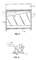
- the interior of the housing 44 is divided into an upper light box section 60 and a lower exposure section 62 by an opaque baffle 64 and a diffusing screen 66, such as a frosted glass plate, which extend between the side walls 48 and 50 (Fig. 3).
- the interior walls of the light box section 60 are made white to maximize light transmission, whereas the interior walls of the exposure section are made black to minimize flare.
- the side wall 48 has a circular opening 68 for accommodating a built-in pressure switch 70 of a preview illuminator 72 mounted in a corner of the exposure section 62 defined by the back wall 46 and side wall 48.
- the preview illuminator 72 includes an incandescent bulb 74 and a battery (not shown).
- the back wall 46 has three rectangular openings 76, 78, 80 and one circular opening 82 supporting, respectively, a light box window 84, a viewfinder optical wedge 86, a photocell optical wedge 88, and a close-up lens and aperture stop supporting and defining member 90.
- the member 90 is cylindrical and has an open end 92 which supports a close-up lens 94 and a closed end 96 having an aperture defining medial slit 98.
- a mounting clamp 100 is fixedly attached to the back wall 46 above the aperture stop 90.
- the mounting clamp 100 is formed of a resilient plastic material so that the adapter 42 can be readily attached to and detached from the front face of the camera 10.
- the clamp 100 includes a pair of arms 102 and 104, each having a respective groove 106 and 108 adapted to receive a respective edge of the cable housing (not shown) which extends between the shutter housing section 18 and the flash unit 28 at the rear of the recess 40.
- the adapter 42 is of a snap-on type adapted to be readily attached and detached from a camera, it is contemplated and will be understood by those skilled in the art that with minor modifications the adapter 42 may be incorporated as a permanent part of a camera dedicated to photographing VIN plates.
- a reflector or mirror 110 is shown mounted on the lower surface of the top wall 52 in a position adjacent the diffusing screen 66 and opposite the light box window 84.
- a light modulator 112 is attached to the upper portion of the diffusing screen 66 adjacent the reflector 110.
- the light modulator 112 has an angled contour 114 so that the modulator is wider at the end adjacent the side wall 50 than at the end adjacent the side wall 48.
- the modulator 112 may be, for example, an opaque coating applied to a select portion of the screen 66.
- the reflector 110 and the diffusing screen 66 are mounted with respect to the adapter 42 to direct the illumination from strobe 30 through the object window 84 at an angle of approximately 30° to form a shadow from the numbers on the VIN plate and thus enhance recognition of the numbers in the photograph.
- the front wall 56 at the distal end of the adapter 42 is located in a plane which is approximately 120° to the optical axis 130 so as to minimize or essentially preclude reflections from the vehicle windshield to the lens 22 of the camera 10 when the camera and adapter are assembled and placed in engagement with the vehicle windshield, as later explained in detail with regard to Fig. 4, while enhancing viewing and photographing of the auto VIN plate through the conventionally inclined windshield.
- the reflector 110 is mounted at an angle of approximatley 20° to the optical axis 130.
- the camera strobe 30, in conjunction with the reflector 110 and diffusing screen 66 provide means for producing a pulse of exposure illumination and for directing the illumination through the object window 58 and the vehicle windshield to illuminate the VIN plate therebehind.
- the inclined illumination also serves to illuminate an information label 120 mounted below the object window 58 as explained in detail below.
- the adapter provides a fully light-tight assembly, and while the latter is preferred to eliminate spurious light from reaching the exposure angle of the lens, an opaque enclosure is not an absolute necessity.
- the adapter section 62 spaces the camera lens a predetermined distance, frames the scene area to be photographed, and with the inclined front wall 56 minimizes and/or precludes windshield reflections from reaching the lens.
- Much of the spurious light which could enter the lens exposure angle tends to eminate from areas adjoining the distal end of the adapter or, that is, near the object window. Consequently, it is preferable that at least some portions of the adapter section 62 near its distal end be light blocking, but as the lens end of this section is approached, there is less concern with light blocking.
- a similar concern also applies to the adapter section 60.
- an opaque enclosure is more necessary or desirable near the distal end of this section than at its end bordering the flash window 84.
- a pair of L-shaped brackets 116 and 118 are attached to the inner surface of the front wall 56 below the object window 58 for supporting an information bearing label 120.
- a neutral density filter 119 is affixed to the brackets 116 and 118 to reduce the flash illumination of the label to approximately one-quarter of its expected illumination in order to compensate for its shorter distance as compared to the VIN plate distance.
- the side wall 50 includes a slit or cut-out 122 which provides for insertion and removal of the label 120 into and from the brackets 116 and 118.
- the label 120 has a length greater than the width of the housing 42 by an amount sufficient to provide a tab which extends from the housing and is easily grasped by a camera operator and that an information bearing portion of the label 120 corresponds to the width of the object window 58.
- the information on label 120 can be the name of the state agency, insurance company or other entity, as well as that of the vehicle owner, or other information pertinent to the recording operation.
- the use of a lable is, of course, optional and can be omitted.
- the label support is permanently secured in the front wall 56.
- the secton of the wall 56 carrying the label brackets 116 and 118 may be hinged to the adapter base 54 to allow it to swing away from the adaptor front and thereby extend the object window 58 to the base 54.
- this portion of the front wall 56 may be formed as a removable member releasably secured to the adapter 42 for mounting select labels.
- a camera operator will first attach the adapter 42 to the front of the camera 10 as shown by the dashed lines in Fig. 1 to form the camera and adapter combination shown in Fig. 4.
- the arms 102 and 104 of the mounting clamp 100 are inserted into the recess 40 in the shutter housing section 18 to the point where the grooves 106 and 108 snap into position on the cable housing (not shown).
- the aperture stop 92 is received within the opening surrounding the objective lens 22, the lower part of the back wall 46 abuts with the front face 20 of the shutter housing section 18, and the upper part of the back wall 46 abuts with the front face of the flash unit 28. Further, in this position, the light box window 84, viewfinder wedge 86, photocell wedge 88, and aperture stop 90 overlie the flash emitting element 30, viewfinder window 24, photocell window 26, and objective lens 22, respectively. Also, when the adapter is in the operative position shown in Fig. 4, the optical axis of the close-up lens 94 and the aperture 98 are co-axial with the optical axis 130 of the objective lens 22.
- the operator will place the front wall 56 of the housing 44 against the windshield 124 of the vehicle 128 so that the objective window 58 generally overlies the VIN plate. Inasmuch as the adapter is approximately five inches in length, the camera lens will be automatically positioned approximately this distance above the windshield.
- the operator will depress the pressure switch 70 to actuate the preview illuminator 72 to illuminate the VIN plate through the windshield 130 while viewing the VIN plate through the viewfinder eyepiece 36.
- the viewfinder eyepiece 36 the operator can view both the VIN plate and the label 120 to ensure that the plate and the information bearing portion of the label are aligned with the object window 58.
- the final step for the camera operator is to depress the exposure cycle initiating button 38.
- the electrical control system of the camera 10 initiates an exposure cycle as is well known in the instant camera art.
- a photocell located behind the photocell window 26 senses scene light and determines the need for a flash exposure.
- the camera exposure control system causes the shutter to open and activates the flash emitting element 30.
- the flash illumination passes through the light box window 84 and into the light box 60 where it strikes the mirror 110 and is reflected toward the diffusing screen 66.
- the light modulator 112 blocks at least some of the direct illumination from the flash emitting element 30 and is tapered at 114 to compensate for the fact that the emitting element 30 is located to one side of the optical axis 130.
- the illumination which passes through the diffusing screen 66 is not only diffused, but more importantly, is directed at a sharp angle with respect to the optical axis 130 so as to illuminate the VIN plate through the windshield 124 and the label 120 while providing a shadow from the VIN plate numbers and letters to enhance the photographic result. Since the aperture stop 90 increases the depth of field to several inches, the VIN plate and label information images are in focus even with the VIN plate being normally located a short distance behind he windshield 124.
- the viewfinder optical wedge 86 and the photocell optical wedge 88 correct for parallax due to the closeness, about 6 inches, of the VIN plate and label 120 to the viewfinder window 24 and the photocell window 26.
- the photocell located behind the photocell optical wedge 88 and the photocell window 26 senses the reflected flash illumination and provides a signal to the camera control system to quench the camera strobe and to close the camera shutter and end the exposure cycle.
- the aperture stop in the present embodiment is a slit 98, which advantageously effectively accommodates the elongated VIN plate.
- the slit 98 aligned with the VIN plate provides a large depth of field to accommodate the variations in VIN plate position while considerably increasing the light transmission for exposure as compared to a circular aperture.
- the slit is approximately 1/16 inch wide and mounted in the end of the adapter 42 just over the surface of the camera lens 22 so as to increase the depth of field of the camera to 3 to 4 inches.
- the close-up lens 94 in conjunction with the camera lens 22, alters the camera fixed focus to approximately 6 inches, assembly of the 5 inch long adapter 42 to the camera 10 will cause the system to be best focused at approximately one inch beyond the distal end 58 of the adapter, as measured along the optical axis 130, and accounting for windshield thickness, will be best focused just less than one inch beyond or behind the windshield when the system is in operative position on a vehicle. Consequently, when the system is in operation, while its best focus will be just less than one inch behind the windshield, it will, due to the 3 to 4 inches depth of field, provide adequate photographic resolution for scene information located between just in front of the windshield to approximately 3 inches behind the windshield. Hence, the system nicely accommodates both the label (located just in front of the windshield) and the VIN plate whose distance varies behind the windshield.
- the slit aperture importantly provides good depth of field to accommodate the variation in location of the VIN plate, with more exposure light than to be expected from a circular aperture, the system still requires a large amount of flash light which is provided by the efficient light directing section 60 in combination with the angled mounting plane of the end 58 of the adapter which facilitates a large flash of illumination through the windshield with minimum exposure interfering reflections therefrom.
- the longitudinal axis of the slit 98 is parallel to the plane of the base 54 of the adapter and to the longitudinal axis of the object window 58, and when assembled to the camera 10 is parallel to its base 12.
- the slit 98, the object window and the label support while remaining parallel to each other, may be rotated at any angle with respect to the camera (e.g., at 90° to the camera base 12) to accommodate particular operator positions for photographing the VIN plate wile standing alongside the vehicle.
- the vehicle identification apparatus of the present invention has, for example, the advantage of facilitating the performance of an automobile insurance adjuster who has to appraise the damage done to a particular automobile.
- the adjuster can use a conventional un-modified instant camera to photograph the damaged portion of the automobile and the automobile license plate, etc. Then, the adjuster can attach the present vehicle identification adapter to the camera and photograph the VIN of the automobile. It is contemplated that modifications, changes or both modifications and changes may be made in the illustrated embodiment without departure from the invention. For example, while the illustrated and described embodiment is adapted for use with a viewfinder type instant camera, it is contemplated that the adapter may be modified for use with a single lens reflect camera.
- the camera apparatus includes a camera and adapter, and as indicated previously, the invention can be accommodated in a single unit. In the latter case, as previously indicated, any angle of orientation between the camera viewing system, the holding of the camera by the operator and the film, can be utilized depending on various design considerations.
- the strobe and light directing arrangement may be provided as an integral unit adjoining the object window, and other aspects of the camera, such as the viewing and light evaluation, modified and positioned as desired.
Landscapes
- Physics & Mathematics (AREA)
- General Physics & Mathematics (AREA)
- Fittings On The Vehicle Exterior For Carrying Loads, And Devices For Holding Or Mounting Articles (AREA)
- Traffic Control Systems (AREA)
- Stroboscope Apparatuses (AREA)
- Accessories Of Cameras (AREA)
Priority Applications (1)
| Application Number | Priority Date | Filing Date | Title |
|---|---|---|---|
| AT89114112T ATE99812T1 (de) | 1988-09-09 | 1989-07-31 | Kamera zur fahrzeugidentifikation. |
Applications Claiming Priority (2)
| Application Number | Priority Date | Filing Date | Title |
|---|---|---|---|
| US242178 | 1988-09-09 | ||
| US07/242,178 US4855770A (en) | 1988-09-09 | 1988-09-09 | Vehicle identification camera |
Publications (3)
| Publication Number | Publication Date |
|---|---|
| EP0357947A2 true EP0357947A2 (de) | 1990-03-14 |
| EP0357947A3 EP0357947A3 (en) | 1990-05-23 |
| EP0357947B1 EP0357947B1 (de) | 1994-01-05 |
Family
ID=22913763
Family Applications (1)
| Application Number | Title | Priority Date | Filing Date |
|---|---|---|---|
| EP89114112A Expired - Lifetime EP0357947B1 (de) | 1988-09-09 | 1989-07-31 | Kamera zur Fahrzeugidentifikation |
Country Status (7)
| Country | Link |
|---|---|
| US (1) | US4855770A (de) |
| EP (1) | EP0357947B1 (de) |
| JP (1) | JP2781414B2 (de) |
| AT (1) | ATE99812T1 (de) |
| CA (1) | CA1307692C (de) |
| DE (2) | DE357947T1 (de) |
| ES (1) | ES2014387T3 (de) |
Families Citing this family (19)
| Publication number | Priority date | Publication date | Assignee | Title |
|---|---|---|---|---|
| US5181059A (en) * | 1991-01-18 | 1993-01-19 | Polaroid Corporation | Camera adaptor kit |
| DE69330513D1 (de) * | 1992-03-20 | 2001-09-06 | Commw Scient Ind Res Org | Gegenstands-überwachungsystem |
| JP2783047B2 (ja) * | 1992-03-27 | 1998-08-06 | 松下電器産業株式会社 | 光波長変換素子およびそれを用いたレーザ光源 |
| DE19753514A1 (de) * | 1997-12-03 | 1999-06-17 | Herbert Siekmann | Kraftfahrzeug mit Rangierhilfe |
| KR100368000B1 (ko) * | 1999-03-24 | 2003-01-14 | 조성환 | 카메라용 링 라이트 가이드 장치 |
| US6965324B1 (en) * | 2000-10-21 | 2005-11-15 | Robert W. Suggs, Sr. | Automotive picture and data acquisition center and method |
| US6751364B2 (en) * | 2001-10-15 | 2004-06-15 | Tyson Fresh Meats, Inc. | Image analysis systems for grading of meat, predicting quality of meat and/or predicting meat yield of an animal carcass |
| JP4109908B2 (ja) * | 2002-06-11 | 2008-07-02 | 株式会社東海理化電機製作所 | 車両用ミラー装置 |
| JP2005326998A (ja) * | 2004-05-13 | 2005-11-24 | Honda Motor Co Ltd | 車輌査定支援ロボット及びこれを用いた車輌査定システム |
| US20070074199A1 (en) * | 2005-09-27 | 2007-03-29 | Sebastian Schoenberg | Method and apparatus for delivering microcode updates through virtual machine operations |
| JP2011166677A (ja) * | 2010-02-15 | 2011-08-25 | Seiko Epson Corp | 画像表示装置、明るさ制御方法および明るさ制御プログラム |
| JP2011164536A (ja) * | 2010-02-15 | 2011-08-25 | Seiko Epson Corp | 画像表示装置、明るさ制御方法および明るさ制御プログラム |
| JP2011166679A (ja) * | 2010-02-15 | 2011-08-25 | Seiko Epson Corp | 画像表示装置、明るさ制御方法および明るさ制御プログラム |
| JP2011166678A (ja) * | 2010-02-15 | 2011-08-25 | Seiko Epson Corp | 画像表示装置、明るさ制御方法および明るさ制御プログラム |
| JP6052246B2 (ja) * | 2014-07-10 | 2016-12-27 | トヨタ自動車株式会社 | 車載カメラの取り付け構造 |
| US9772383B2 (en) | 2015-03-04 | 2017-09-26 | Johnson Controls Technology Company | Battery test report system and method |
| US10816605B2 (en) | 2015-03-11 | 2020-10-27 | Cps Technology Holdings Llc | Battery test system with camera |
| US11720005B2 (en) | 2019-02-19 | 2023-08-08 | Carvana, LLC | Camera mount for vehicle photographic chambers |
| WO2020215060A1 (en) * | 2019-04-19 | 2020-10-22 | Ovad Custom Stages, Llc | Photographic paddle and process of use thereof |
Family Cites Families (12)
| Publication number | Priority date | Publication date | Assignee | Title |
|---|---|---|---|---|
| GB208946A (en) * | 1923-02-21 | 1924-01-03 | Rupert James Rogers | Improvements in incandescent gas burners |
| US2314829A (en) * | 1940-03-12 | 1943-03-23 | Robert H Hunter | Photographing unit |
| US2433129A (en) * | 1943-12-30 | 1947-12-23 | Westinghouse Electric Corp | Photofluorographic camera and control |
| US3195431A (en) * | 1961-08-08 | 1965-07-20 | Polaroid Corp | Photographic accessory |
| CH391311A (de) * | 1962-01-22 | 1965-04-30 | Alos Ag | Gerät zum Ausleuchten und Photographieren einer Gegenstandsfläche mit reflektierenden Flächenteilen |
| US3514206A (en) * | 1967-07-14 | 1970-05-26 | Eastman Kodak Co | Apparatus for making close-up photographs with a photoflash camera |
| US4093364A (en) * | 1977-02-04 | 1978-06-06 | Miller Keith G | Dual path photographic camera for use in motor vehicles |
| US4245902A (en) * | 1978-10-18 | 1981-01-20 | Cataldo Joseph W | Bank deposit identification device |
| DE2851126C3 (de) * | 1978-11-25 | 1981-09-10 | Kernforschungszentrum Karlsruhe Gmbh, 7500 Karlsruhe | Einrichtung zum Überwachen von Objekten |
| DE3166877D1 (en) * | 1980-12-15 | 1984-11-29 | Roehm Gmbh | Photographic device for the surveyance of the inside of a motor vehicle |
| US4701039A (en) * | 1985-11-01 | 1987-10-20 | Polaroid Corporation | Copy accessory for instant camera |
| US4717930A (en) * | 1986-10-14 | 1988-01-05 | Wheeler Alton D | Instant photography with superimposed graphics |
-
1988
- 1988-09-09 US US07/242,178 patent/US4855770A/en not_active Expired - Lifetime
-
1989
- 1989-06-05 CA CA000601756A patent/CA1307692C/en not_active Expired - Fee Related
- 1989-07-07 JP JP1174293A patent/JP2781414B2/ja not_active Expired - Lifetime
- 1989-07-31 AT AT89114112T patent/ATE99812T1/de not_active IP Right Cessation
- 1989-07-31 DE DE198989114112T patent/DE357947T1/de active Pending
- 1989-07-31 DE DE89114112T patent/DE68912035T2/de not_active Expired - Fee Related
- 1989-07-31 EP EP89114112A patent/EP0357947B1/de not_active Expired - Lifetime
- 1989-07-31 ES ES89114112T patent/ES2014387T3/es not_active Expired - Lifetime
Also Published As
| Publication number | Publication date |
|---|---|
| EP0357947A3 (en) | 1990-05-23 |
| JP2781414B2 (ja) | 1998-07-30 |
| DE68912035T2 (de) | 1994-04-28 |
| US4855770A (en) | 1989-08-08 |
| EP0357947B1 (de) | 1994-01-05 |
| ES2014387T3 (es) | 1994-05-01 |
| CA1307692C (en) | 1992-09-22 |
| JPH0282232A (ja) | 1990-03-22 |
| DE357947T1 (de) | 1990-07-05 |
| ATE99812T1 (de) | 1994-01-15 |
| ES2014387A4 (es) | 1990-07-16 |
| DE68912035D1 (de) | 1994-02-17 |
Similar Documents
| Publication | Publication Date | Title |
|---|---|---|
| US4855770A (en) | Vehicle identification camera | |
| US4557571A (en) | Compact camera with flash unit | |
| US4248510A (en) | Identification card camera system | |
| US5721995A (en) | Lens-fitted photographic film unit having shutter with connection lever and crank lever | |
| US5486885A (en) | Character image display apparatus for a camera | |
| US5521662A (en) | Film viewer | |
| US5471268A (en) | Character imprinting device for a camera | |
| JPS5945971B2 (ja) | デ−タ写し込み装置 | |
| US5740483A (en) | Data recording device for camera | |
| US5181059A (en) | Camera adaptor kit | |
| US4028713A (en) | Data recording camera | |
| US5262808A (en) | Camera, accessories and method of taking photographs | |
| US6243536B1 (en) | Lens-fitted photo film unit with data recording device | |
| US6587643B2 (en) | Lens-fitted photo film unit and photofinishing method | |
| US5075705A (en) | Methods of an apparatus for providing printed photographs with a border | |
| JPS5916915Y2 (ja) | 証明カ−ド作成用の撮影装置 | |
| US3726192A (en) | Photographic camera | |
| EP0037316B1 (de) | Kopiergerät zum Beurkunden eines Originals | |
| EP0678769B1 (de) | Abdeckvorrichtung für Negativfilme | |
| JPWO1999059027A1 (ja) | データ写し込み装置及びデータ写し込み装置を備えたカメラ | |
| US5122832A (en) | Printing control device | |
| NL8005004A (nl) | Inrichting voor het vervaardigen van fotografische afdrukken. | |
| JPH07146513A (ja) | カメラ用被写体データ写し込み装置 | |
| JP2003087634A (ja) | フィルム読取装置 | |
| JP3882177B2 (ja) | カメラ |
Legal Events
| Date | Code | Title | Description |
|---|---|---|---|
| PUAI | Public reference made under article 153(3) epc to a published international application that has entered the european phase |
Free format text: ORIGINAL CODE: 0009012 |
|
| AK | Designated contracting states |
Kind code of ref document: A2 Designated state(s): AT CH DE ES FR GB IT LI NL SE |
|
| ITCL | It: translation for ep claims filed |
Representative=s name: RICCARDI SERGIO & CO. |
|
| PUAL | Search report despatched |
Free format text: ORIGINAL CODE: 0009013 |
|
| TCAT | At: translation of patent claims filed | ||
| EL | Fr: translation of claims filed | ||
| TCNL | Nl: translation of patent claims filed | ||
| AK | Designated contracting states |
Kind code of ref document: A3 Designated state(s): AT CH DE ES FR GB IT LI NL SE |
|
| DET | De: translation of patent claims | ||
| 17P | Request for examination filed |
Effective date: 19901017 |
|
| 17Q | First examination report despatched |
Effective date: 19921105 |
|
| GRAA | (expected) grant |
Free format text: ORIGINAL CODE: 0009210 |
|
| AK | Designated contracting states |
Kind code of ref document: B1 Designated state(s): AT CH DE ES FR GB IT LI NL SE |
|
| REF | Corresponds to: |
Ref document number: 99812 Country of ref document: AT Date of ref document: 19940115 Kind code of ref document: T |
|
| ET | Fr: translation filed | ||
| REF | Corresponds to: |
Ref document number: 68912035 Country of ref document: DE Date of ref document: 19940217 |
|
| ITF | It: translation for a ep patent filed | ||
| REG | Reference to a national code |
Ref country code: ES Ref legal event code: FG2A Ref document number: 2014387 Country of ref document: ES Kind code of ref document: T3 |
|
| PLBE | No opposition filed within time limit |
Free format text: ORIGINAL CODE: 0009261 |
|
| STAA | Information on the status of an ep patent application or granted ep patent |
Free format text: STATUS: NO OPPOSITION FILED WITHIN TIME LIMIT |
|
| 26N | No opposition filed | ||
| EAL | Se: european patent in force in sweden |
Ref document number: 89114112.9 |
|
| PGFP | Annual fee paid to national office [announced via postgrant information from national office to epo] |
Ref country code: AT Payment date: 20000612 Year of fee payment: 12 |
|
| PGFP | Annual fee paid to national office [announced via postgrant information from national office to epo] |
Ref country code: SE Payment date: 20000620 Year of fee payment: 12 |
|
| PGFP | Annual fee paid to national office [announced via postgrant information from national office to epo] |
Ref country code: FR Payment date: 20000621 Year of fee payment: 12 Ref country code: CH Payment date: 20000621 Year of fee payment: 12 |
|
| PGFP | Annual fee paid to national office [announced via postgrant information from national office to epo] |
Ref country code: GB Payment date: 20000622 Year of fee payment: 12 |
|
| PGFP | Annual fee paid to national office [announced via postgrant information from national office to epo] |
Ref country code: NL Payment date: 20000627 Year of fee payment: 12 |
|
| PGFP | Annual fee paid to national office [announced via postgrant information from national office to epo] |
Ref country code: DE Payment date: 20000629 Year of fee payment: 12 |
|
| PGFP | Annual fee paid to national office [announced via postgrant information from national office to epo] |
Ref country code: ES Payment date: 20000704 Year of fee payment: 12 |
|
| PG25 | Lapsed in a contracting state [announced via postgrant information from national office to epo] |
Ref country code: LI Free format text: LAPSE BECAUSE OF NON-PAYMENT OF DUE FEES Effective date: 20010731 Ref country code: GB Free format text: LAPSE BECAUSE OF NON-PAYMENT OF DUE FEES Effective date: 20010731 Ref country code: CH Free format text: LAPSE BECAUSE OF NON-PAYMENT OF DUE FEES Effective date: 20010731 Ref country code: AT Free format text: LAPSE BECAUSE OF NON-PAYMENT OF DUE FEES Effective date: 20010731 |
|
| PG25 | Lapsed in a contracting state [announced via postgrant information from national office to epo] |
Ref country code: SE Free format text: LAPSE BECAUSE OF NON-PAYMENT OF DUE FEES Effective date: 20010801 Ref country code: ES Free format text: LAPSE BECAUSE OF NON-PAYMENT OF DUE FEES Effective date: 20010801 |
|
| PG25 | Lapsed in a contracting state [announced via postgrant information from national office to epo] |
Ref country code: NL Free format text: LAPSE BECAUSE OF NON-PAYMENT OF DUE FEES Effective date: 20020201 |
|
| REG | Reference to a national code |
Ref country code: CH Ref legal event code: PL |
|
| GBPC | Gb: european patent ceased through non-payment of renewal fee |
Effective date: 20010731 |
|
| PG25 | Lapsed in a contracting state [announced via postgrant information from national office to epo] |
Ref country code: FR Free format text: LAPSE BECAUSE OF NON-PAYMENT OF DUE FEES Effective date: 20020329 |
|
| EUG | Se: european patent has lapsed |
Ref document number: 89114112.9 |
|
| NLV4 | Nl: lapsed or anulled due to non-payment of the annual fee |
Effective date: 20020201 |
|
| PG25 | Lapsed in a contracting state [announced via postgrant information from national office to epo] |
Ref country code: DE Free format text: LAPSE BECAUSE OF NON-PAYMENT OF DUE FEES Effective date: 20020501 |
|
| REG | Reference to a national code |
Ref country code: FR Ref legal event code: ST |
|
| REG | Reference to a national code |
Ref country code: ES Ref legal event code: FD2A Effective date: 20020810 |
|
| PG25 | Lapsed in a contracting state [announced via postgrant information from national office to epo] |
Ref country code: IT Free format text: LAPSE BECAUSE OF NON-PAYMENT OF DUE FEES;WARNING: LAPSES OF ITALIAN PATENTS WITH EFFECTIVE DATE BEFORE 2007 MAY HAVE OCCURRED AT ANY TIME BEFORE 2007. THE CORRECT EFFECTIVE DATE MAY BE DIFFERENT FROM THE ONE RECORDED. Effective date: 20050731 |