EP0357950A2 - Ensemble d'éléments de construction en coin emboîtables - Google Patents
Ensemble d'éléments de construction en coin emboîtables Download PDFInfo
- Publication number
- EP0357950A2 EP0357950A2 EP89114228A EP89114228A EP0357950A2 EP 0357950 A2 EP0357950 A2 EP 0357950A2 EP 89114228 A EP89114228 A EP 89114228A EP 89114228 A EP89114228 A EP 89114228A EP 0357950 A2 EP0357950 A2 EP 0357950A2
- Authority
- EP
- European Patent Office
- Prior art keywords
- angle
- stones
- leg
- stone
- thigh
- Prior art date
- Legal status (The legal status is an assumption and is not a legal conclusion. Google has not performed a legal analysis and makes no representation as to the accuracy of the status listed.)
- Granted
Links
Images






Classifications
-
- E—FIXED CONSTRUCTIONS
- E02—HYDRAULIC ENGINEERING; FOUNDATIONS; SOIL SHIFTING
- E02D—FOUNDATIONS; EXCAVATIONS; EMBANKMENTS; UNDERGROUND OR UNDERWATER STRUCTURES
- E02D17/00—Excavations; Bordering of excavations; Making embankments
- E02D17/20—Securing of slopes or inclines
- E02D17/202—Securing of slopes or inclines with flexible securing means
-
- A—HUMAN NECESSITIES
- A01—AGRICULTURE; FORESTRY; ANIMAL HUSBANDRY; HUNTING; TRAPPING; FISHING
- A01G—HORTICULTURE; CULTIVATION OF VEGETABLES, FLOWERS, RICE, FRUIT, VINES, HOPS OR SEAWEED; FORESTRY; WATERING
- A01G9/00—Cultivation in receptacles, forcing-frames or greenhouses; Edging for beds, lawn or the like
- A01G9/02—Receptacles, e.g. flower-pots or boxes; Glasses for cultivating flowers
- A01G9/022—Pots for vertical horticulture
- A01G9/025—Containers and elements for greening walls
-
- E—FIXED CONSTRUCTIONS
- E01—CONSTRUCTION OF ROADS, RAILWAYS, OR BRIDGES
- E01F—ADDITIONAL WORK, SUCH AS EQUIPPING ROADS OR THE CONSTRUCTION OF PLATFORMS, HELICOPTER LANDING STAGES, SIGNS, SNOW FENCES, OR THE LIKE
- E01F8/00—Arrangements for absorbing or reflecting air-transmitted noise from road or railway traffic
- E01F8/02—Arrangements for absorbing or reflecting air-transmitted noise from road or railway traffic specially adapted for sustaining vegetation or for accommodating plants ; Embankment-type or crib-type noise barriers; Retaining walls specially adapted to absorb or reflect noise
- E01F8/021—Arrangements for absorbing or reflecting air-transmitted noise from road or railway traffic specially adapted for sustaining vegetation or for accommodating plants ; Embankment-type or crib-type noise barriers; Retaining walls specially adapted to absorb or reflect noise with integral support structure
- E01F8/023—Arrangements for absorbing or reflecting air-transmitted noise from road or railway traffic specially adapted for sustaining vegetation or for accommodating plants ; Embankment-type or crib-type noise barriers; Retaining walls specially adapted to absorb or reflect noise with integral support structure made of stacked or staggered elements, e.g. hollow
-
- E—FIXED CONSTRUCTIONS
- E02—HYDRAULIC ENGINEERING; FOUNDATIONS; SOIL SHIFTING
- E02D—FOUNDATIONS; EXCAVATIONS; EMBANKMENTS; UNDERGROUND OR UNDERWATER STRUCTURES
- E02D29/00—Independent underground or underwater structures; Retaining walls
- E02D29/02—Retaining or protecting walls
- E02D29/025—Retaining or protecting walls made up of similar modular elements stacked without mortar
-
- Y—GENERAL TAGGING OF NEW TECHNOLOGICAL DEVELOPMENTS; GENERAL TAGGING OF CROSS-SECTIONAL TECHNOLOGIES SPANNING OVER SEVERAL SECTIONS OF THE IPC; TECHNICAL SUBJECTS COVERED BY FORMER USPC CROSS-REFERENCE ART COLLECTIONS [XRACs] AND DIGESTS
- Y02—TECHNOLOGIES OR APPLICATIONS FOR MITIGATION OR ADAPTATION AGAINST CLIMATE CHANGE
- Y02P—CLIMATE CHANGE MITIGATION TECHNOLOGIES IN THE PRODUCTION OR PROCESSING OF GOODS
- Y02P60/00—Technologies relating to agriculture, livestock or agroalimentary industries
- Y02P60/20—Reduction of greenhouse gas [GHG] emissions in agriculture, e.g. CO2
Definitions
- the invention relates to a kit of interlocking angle elements for the creation of plantable view and soundproof walls, slope supports and supports as well as property path and bed surrounds, prefabricated buildings and toys according to the generic features mentioned in the preamble of claim 1.
- L-stones Concrete blocks of an angular shape, which are known commercially under the name "L-stones" or angle stones, are common. These L-stones have parallel transverse edges, or top and bottom surfaces, a right-angled, isosceles floor plan with approx. 40 cm leg length, a height of approx. 40 cm, a material thickness of approx. 6 to 10 cm and a weight of approx. 51 kg. Their thigh ends are at an obtuse angle at 90 degrees to the thigh edges. They have smooth outer surfaces and are used primarily by landscape gardeners and do-it-yourselfers for the design and edging of raised beds, sandboxes, terraces, etc.
- a disadvantage of the known L-stone is, above all, its obtuse-angled formation of the leg ends, which makes the L-stone unsuitable for joining together with parallel abutting surfaces in the longitudinal and transverse directions and for masonry in the dressing.
- its application possibilities are limited and can only be used in a lying position, i.e. with a transverse edge parallel to the floor.
- L-stones cannot be pegged or interlocked at their butt joints. They are held by gravity and material-related friction with vertical butt joints on top of or next to each other. It is not possible to use staggered butt joints or to form supports and pillars. Nor can vertical pillars of earth and planting bags be built in tiers.
- G 82 23 515 a concrete ring with four alternately curved outwards and inwards walls is known, in which two opposite sides are designed convex and concave.
- This form stone can be moved to free-standing and unilaterally erected walls by rows next to and on top of each other.
- the disadvantage of this laterally closed hollow stone, open at the top and bottom, is its large envelope, which has an expensive empty space for production, storage and transport. In addition, its use is limited to walls and embankments.
- trough-shaped embankment stones with disadvantages similar to G 82 23 515 are known under GM 76 14 681 and 32 33 014.
- the 32 33 014 shows a hollow stone as a regular closed octagon with a flat underside and with incisions at the top on every other polygon side. They allow interlocking layers to be interlocked, but only with gradual staggering for one-sided slope fastening. These trough stones are not suitable for free-standing, plantable walls.
- the invention has for its object to form a kit of angle elements of the type mentioned so that the disadvantages of the known shaped blocks are avoided. Instead, with as few, coordinated system parts as possible, different types of solutions should be able to be implemented cost-effectively, ecologically and aesthetically.
- the statically and economically favorable shape of the angle stone should be made universally usable for the construction of walls. Its stackability should be used as a weight and cost advantage in production, storage, transport and assembly.
- the angle stones should be formed on the joint so that the same stones can be extended to form free-standing and / or one-sided plant walls, butting against each other.
- the angle blocks for walls and supports of great stability and rigidity should also be dry can be bricked up without mortar.
- Vertical wall surfaces should be green and ecologically usable. Sound insulation should be increased through soil fillings and plantability.
- the niches formed by triangular recesses should be able to be turned into vertical planting columns and terraces.
- Terrace-shaped plant bags should be able to be connected to each other and to the grown soil with the help of vertical columns of earth.
- Free-standing plant pillars are intended to beautify the environment individually or in combination.
- Angle stones are said to be able to be moved to beautiful, as well as to statically load-bearing plant walls, pillars, embankment walls and pillars.
- the hollow chambers should be able to be filled with reinforcement and filling concrete and to be designed as reinforced concrete columns and retaining walls. Planners and contractors in gardening and landscaping are to be offered new design options.
- Angle elements with acute-angled leg ends 13 and flattened leg backs are installed according to the principle of a wall structure with butt joints offset in layers.
- the angle stones 1, 2, 3, 61, 69, 70 and 98 offer the basis for with their wide, angled basic shape a tilt-proof stand.
- the angular shape has a favorable moment of inertia, the center of gravity being within the triangular shape, but outside the cross-sectional area.
- the angular shape which is open on one side, allows a material cross-section that is smaller than that of a closed body and is ideal for space-saving stacking without having to pack cavities.
- the stackability of a product is an important cost factor for production, warehousing and transport. The larger the number of pieces per pallet, the cheaper the piece costs.
- the 60-degree Winkelstein 61 has several additional advantages: It has an equilateral, even larger footprint, which means it also has a greater moment of inertia, greater resistance to buckling and a better capacity for soil. It can be used to form hexagonal, star-shaped planting columns (Fig. 10), free-standing and / or expandable on each side. Freestanding, triangular planting columns are also possible (see Figures 10 and 11). Zigzag walls with depth and large earth volume on both sides are to be formed from individual shaped stones as well as from wall-high elements (Fig. 8, 11), each with storey plates 5 and 5 ° to plant terraces 7.
- the low weight of the angle stones 1 and 61 of approx. 28 kg and the advantageous dimensions of 40 cm leg length, 25 cm height and approx. 6.5 cm wall thickness also allow individuals to brick up without too much physical effort. When using lightweight concrete, these weights can be reduced even further.
- the dimensions mentioned can be changed as required and adapted to the objects.
- leg tips 13 and the stone back 14 according to claim 1, shown in Fig. 1, allows the angular stones to be joined together with parallel abutting surfaces in the longitudinal 29, in the transverse 30, in the leg direction 32 and crossed and thereby allows a regular bridging of the vertical butt joints 26 through the center of the stone 31 of the stones 1, 3 and 61 rotated thereon in the next layer by 90 or 180 degrees.
- angular blocks 1, 2, 3 and 61 result in a zigzag pattern, the butt joints 26 of which are bridged in the next layer by the stone centers 31 of the angular blocks rotated by 180 degrees. This creates a stable wall structure and a stable wall on the spot.
- the regular zigzag pattern of a floor plan according to Fig. 1, 8, 9 and 11 gives the free-standing wall similar views on both sides of the strongly structured surfaces with surface recesses on more than 80% of the respective surface and depths of up to to 40 cm.
- the sloping recessed surfaces are visually appealing to the viewer, absorbing and reflecting on incoming sound and detonation waves.
- at least partially niches filled with soil and the planting results in additional sound absorption and less reflection, so that, when compared to existing products, highly absorbing effects can be expected from the wall according to the invention.
- the invention also allows ascending and descending bearing joints 42 and wall closures.
- the angle block 3, shown in Fig.9, Fig.9a to 9c, has seen in vertical longitudinal section two parallel, V-shaped bed joints 42 at a uniform distance from the stone height H, which is from the stone center 31 at about 45 degrees to the two leg ends climb up or down.
- the bed joint 33 seen in the installed state, runs horizontally.
- acute-angled corner stones 3 are tilted by 180 degrees and saddled with their incision in the middle of the stone onto a point and over a butt joint of the two lower stones. Its pointed leg ends, which now protrude downward, reach into the incision of two acute angle stones below. In this way, the butt joints 26 are bridged regularly in the middle of the stone 31, so that the same regular masonry bond is created even with acute-angled corner stones as in the case of the corner stones described above with horizontal bed joints.
- the first layer should have a horizontal bed joint 33 on the bottom or on an in-situ concrete foundation, while its upper bed joint 42 is formed at an acute angle ascending and descending.
- the ascending and descending bearing joints 42 and wall crowns act as a design-related, dynamic element that can be further emphasized by the colored contrasting of the layers.
- the lateral transverse edges can also be wave-shaped or have different pitch angles.
- the 60-degree angle stones 61 and the third plates 69 and 70 for hexagonal and round columns with rising and falling bearing joints and / or wall crowns and as wall-high elements 2 as shown in FIGS. 7, 8 and 9 can also be designed, which can not only run in a straight line but as broken lines.
- Zigzag-shaped, one- or two-row, wall-high corner elements are assembled to detonation and privacy walls. (Fig. 8)
- Isosceles 1 or isosceles angle stones 98 can be used as stable corner points with plates 99 placed positively between the tips of the legs for plant troughs and for the construction of buildings in prefabricated construction be set (Fig. 12).
- Zigzag-shaped floor plans can be made as in FIGS. 3 , 4 and 11, Fig.3a, 3b, 4a, 4b and 4c shown, stepped down like stair lines over each other to secure embankments.
- the interlocking or doweling of the individual layers is carried out in the case of FIGS. 1 and 4 by means of rod dowels, in the case of FIGS. 2, 3 and 11 by hooking transverse grooves 34.
- the tongue-shaped elevations can also be used in the case of crossovers by cutting out the upstands at the crossing points or subsequently knocking them off with a hammer. The upstands left next to the crossing points remain as shear protection.
- angular stones 1 and 61 can be joined together in pairs at the tips of the legs to form hollow shapes and offset and toothed in the longitudinal direction by half a diagonal length 22 per layer.
- the stone back 14 or leg pairs 13 protruding laterally above the recesses are closed at the bottom, and the stones are interlocked.
- the filled soil is embedded in the plantable projections, releases upward planting terraces 7, which are connected to the core of the earth inside the wall, so that their plant roots reach down to the grown soil can. (see Fig. 2,3)
- FIG. 2 Another way of laying for the planting wall shown in FIG. 2 provides that corner stones with transverse grooves 34 are pushed at the upper transverse edge in the longitudinal direction 29 of the wall and crossed in the middle with the following layer. In every third layer, the angle stones 1 are offset with transverse grooves 34 as transverse clips between two parallel layers in the transverse direction 30 of the wall.
- an existing garden wall 74 with a plant wall without having to tear it down it can be pre-bricked with the semi-rigid wall made of simply crossed angle stones according to Fig. 3, Figs. 3a and 3b, so that the whole thickness of the wall according to Fig .2 to continue.
- the following layers are each rotated by 90 gad and placed on the stone centers 31 with their butt joints 26.
- the same floor plan can also be formed from full trough stones 97 and combined with base plates 55, intermediate plates 54, and cover plates 41 (FIG. 6)
- column layouts of a rectangular outline can be formed in the same way as in C-1.
- the same outline can also be formed from full trough stones 102 (FIG. 12).
- Pieces of staggered angular and segmental stones can be assembled into square or round column floor plans.
- Three elements 69 and 70 each result in hexagonal, twelve-sided and round supports.
- Square columns can be formed from two angle stones 1 and 77, and octagonal columns can be formed from four segment stones 82 each.
- the angle or segment stones 1, 69, 70, 77, 82, 98 are put together in layers to form a closed column floor plan and, according to the bricklayer principle, are placed in the following layer with the stone center 31 on an underlying butt joint 26. (see Fig. 6, Fig. 6a, 6b, 6e, 6f, 6g, 6h, Fig.11, Fig. 11d, 11e, 11f, Fig.12 Fig.12b).
- 90-degree angle stones 1 can be installed in layers of four to three-chamber planting pillars according to Fig. If three 60 degree angle stones 61, each with a 60 degree gap, are put together in a six-chamber planting column on the back, six identical planting chambers are created (see Fig. 10). The next layer is rotated by 60 degrees, so that an angle stone each the space underneath and one Butt joint covered.
- 60-degree angle stones 61 are rotated by 60 degrees per layer and placed directly on top of each other, with three layers each of the three sides is given a plantable opening and two closed sides, with the earth being held back by slabs and shaped into terraces. (without picture)
- the recessed niches can be formed by inserting trapezoidal slabs 5 and 5 ° to plantable terraces with vertical columns of soil 8.
- the necessary floor plates 5 and 5 ° are located with two support points 49 on the vertical wall of the angle stones 1,2,3 and 61.
- the supports are either molded onto the stone in the form of thickening or lateral, groove-shaped depressions, insertion slots or support plates, or can be dowelled laterally after the wall has been built up.
- the tier plates 5 hold the earth core 8 backwards in the niche and, as seen in vertical section, release wedge-shaped, plantable indentations, so-called plant pockets or plant terraces 7.
- the segment-like 6, and straight recesses 6 ° of the floor plates 5 and 5 ° form openings in the installed state at the bottom of the respective planting days.
- the soil filling gliding backwards along the slope of the floor slabs falls through the floor opening 6 and 6 ° in the corner of the niche through to the planting level underneath and, after complete filling, forms natural slope angles of approx. 20 degrees from the outer upper edge 23 of the lower to each floor to the inner lower edge 24 of the upper floor plate 5 and 5 °.
- the design of the planting days according to the invention takes into account the natural settlement phenomena in that the earth can slide along the inclined slabs 5, so that a continuous column of earth always remains in the corner area 6 of the niche. Settlements are automatically fed from the soil content of the individual floors and can be recognized and replenished from the front as subsidence (Fig. 1,7).
- the continuous earth core 8 in the corner of the niche is important for easy-care and successful greening.
- the roots can grow down to the core of the earth and down to the lower levels, with permanent growth down to the ground and, with the help of the capillary effect, supply themselves with moisture. Permanent irrigation can therefore be dispensed with. Individual, isolated plant bags without a vertical earth core would be exposed to dehydration or would have to be artificially irrigated.
- the horizontal surfaces of the planting bags 7 open at the top with plants growing up and down, such as, for. B. ivy, wild wine or similar to plant.
- the wall surface is greened relatively quickly in a punctiform manner, so that even high walls can be fully greened within a short time.
- the planting of vertical concrete walls creates ecologically valuable, visually appealing green areas, while increasing the sound insulation.
- Foot plates 103 formed on angle stones according to claim 40 widen the footprint of the wall. (Fig. 8, Fig.8a). Loads from stuffed earth or other weights that press on the foot plates bring additional resistance to horizontal forces and give a wall equipped with it increased stability. Such a wall can therefore take larger loads, for example as a retaining wall against earth pressure, or it can be built higher in a free-standing installation than comparable walls without base plates.
- Cover plates 104 correspond in their contours to the surface formed from the outer leg edges 18 and a diagonal 22 and are adapted to the upper transverse edge of an angle block 1 with corresponding recesses and can be placed thereon and positively connected. With their help, corner stones can be formed into stools and tables.
- D-4 to D-6 relates to cover plates 41, intermediate plates 54 and base plates 55, which are used for the construction of columns and pillars and are explained in more detail in the description of the figures for FIG. 6, FIG. 6c.
- the floor slabs 10 and 10 ° of Fig. 2 and 3 are required for vertical walls in a crossed manner of displacement to close the cantilevered areas of the angle stones open at the bottom and to use the filled soil for projecting plant terraces.
- the openings for the plantable terraces 7 of FIGS. 2 and 3 can be completely closed with filler stones 57.
- This may be necessary in order to form external hollow chambers, which can be formed by supports 58 to be supported by filling with reinforced concrete.
- Such supports can possibly only in the the lower layers of a wall may be required statically, while the upper layers of the column, filled with earth, are formed into open plant terraces.
- individual hollow chambers can be filled into reinforced concrete supports 58, which are suitable, for example, as shown in FIG. 3, as a stop for sheet piles 59.
- Angle blocks with concrete webs 67 between the legs can be formed into supports by stacking the hollow chambers, which can be reinforced and filled with concrete.
- the struts run parallel to the back of the leg 14 at any point between the tip and back of the leg (Fig.11, Fig.11a).
- these angle blocks can also be horizontally interlocked with one of the joint profiles F-1 to F-15.
- the vertical bevels 76 in the center of the back of the leg 14 have the width and appearance of an butt joint 26 lying above or above and serve as an ornamental design element to continue the butt joints 26 of the layer below in the middle of the stone 31 as a shadow joint 76 (FIG. 1, Fig. 1b)
- the fully solid vertical cross section of the angle stones 1 is suitable for mechanical stone production. Concrete is filled into steel molds from above and compacted. Then the mold opens downwards to let out the earth-moist blank.
- An externally solid cross section 91 has internal hollow chambers according to claim 4 for saving material and weight.
- soft plastic is used sches material, such as clay, extruded as an angle profile and cut from the strand according to the desired length.
- the hollow tubes run parallel to the strand straightening direction in the middle of the leg 32 and are visible at the cut surfaces 23 and 24 as polygonal, round or elliptical holes (Fig. 5, Fig. 5d).
- I-shaped cross sections 92 according to claim 28 have a slim central web in the middle 32 of the legs and in the region of the transverse edges 23 and 24 thickened portions on both sides.
- the central web can be reinforced on both sides by ribs running between the transverse edges.
- Such cross sections 92 can be produced for toys in plastic injection molding, where it is a matter of being able to save expensive material (FIG. 5).
- U-shaped cross sections 93 according to claim 27 have a continuous web in the region of the outer leg edges 18 with two flange portions formed thereon in the region of the transverse edges 23 and 24, which are suitable as grip strips when moving. Wood or concrete can be used as the material.
- Some stone making machines allow e.g. only to leave out grooves in the upper transverse edges, while there must be no incisions in the lower transverse edge.
- the overhead transverse grooves 34 would come into question according to claim 8, which allow a cross-shifting according to Fig. 2 and 3 by the smooth lower transverse edges snap into the transverse grooves 34 of the upper transverse edges of the underlying stone.
- a type of offset according to FIG. 1 would require additional H-profile dowels 88 according to FIG. 5 to be inserted into the transverse grooves 34.
- both the upper and the lower transverse edges each receive transverse grooves 34, which interlock twice by crossing two angle stones.
- transverse edges of angular toy building blocks made of plastic would preferably be profiled in an injection molding process with fine-spaced rows of grooves, which are hardly producible in concrete, according to Claims 14-17, described under F-11 to 14. (Fig. 5 and 11)
- the specified design dimensions can be increased and decreased in proportion almost as required, in accordance with the requirements, the materials used, the means of production and transport and the static calculation.
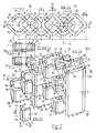
- Fig.1, Fig.1a shows 90-degree angle stones 1 according to claim 1 and 2 in plan, each with their diagonals 22, their stone back 14 and an associated side 60 of the leg tips 13 parallel to the longitudinal center plane 29.
- the projection of the back of the leg 14 onto the central axis 32 of the leg results in a length 71 which is twice as long as the projection 62 of a tip 13 of the leg onto the plane 32.
- the two angle blocks with leg tips 13 pointing downward have a common longitudinal joint M-B in the central wall plane 30.
- This joint M-B is bridged in a second position to be placed on it by the left angle block.
- the left-hand stone which is rotated by 90 degrees, points upwards with its thigh tips 13 and thus covers the two angle stones lying underneath from the middle of the stone 31 to the middle of the stone 31.
- a second angle block 1 with the contact surfaces AM and A ° -M is attached to the right, top angle block 1 from below.
- the two angle stones 1 form a closed, approximately square hollow body for planting vessels and hollow supports.
- the following layer is formed by a further pair of angle blocks rotated by 90 degrees, the butt joints AM of which sit over the center of the block 31 of the lower pair of blocks.
- the upper cross-sectional areas 27 are provided with elevations of a trapezoidal profile parallel to the central leg axis 32 of approximately 2 cm in height
- the lower cross-sectional areas 28 are provided with groove-shaped depressions which are complementary thereto.
- Fig.1c shows the cross section I-I through the angle block 1 of Fig. 1b with cross-section trapezoidal tongue and groove bearing joints 25 as one of several types of teeth.
- Fig.1d shows the cross-section II-II through the angle block 1 of Fig. 1b with dowel holes 35 and rod-shaped dowels 36 in the bearing joints as one of several types of toothing.
- Fig.1e shows the perspective of a typical wall piece made of angle blocks 1, which is created in a wall structure with offset butt joints.
- One of the triangular-shaped niches is sealed off to the open side with slanted floor panels 5, which enclose a vertical earth column 8 in the rear corner area and form planted terraces in stages.
- the closed hollow shape shown on the right is formed from two angular stones touching the inside of the leg tips 13. The stones of the next layer are rotated by 90 degrees, so that one stone center 31 bridges the butt joint 26 below.
- the closed hollow molds can be left hollow, filled with earth, or poured into reinforced concrete columns at any point to stiffen the wall.
- rod dowels 36 with or without a connecting strap 37 are inserted into the complementary round holes 35 of the stacked bricks, with four dowel holes of one leg being aligned with the four dowel holes of the parallel legs of two angle blocks above and / or below .
- horizontal dowelling can be carried out with the aid of tongue and groove teeth 25 according to Fig.1c.
- Fig.1f shows the cross-section of two approximately cake slice-shaped slabs 5 and 5 ° with an acute angle 15 of approx. 70 degrees (at a 90 degree angle between the angle stone legs) which is limited by the tapering outer edges.
- the floor slabs 5 and 5 ° are supported in a longitudinal axis running parallel to 29 with a slightly forward load distribution by two support points 49 formed on or anchored to the side of the angle stone wall, pressed forward by the dead weight and the earth load and fixed in an inclined position to the rear. Tilting forward is prevented in that the outer edges of the floor plate are pushed up in the rear area and wedged on the walls of the angle plates.
- the segment-like recess 6 and 6 ° at the top of the floor slab delimits a cavity as a quarter circle of approx. 17 cm radius, which can be filled with earth, and connects the individual planting days with one another down to the grown soil as a continuous, vertical column of earth.
- the roots can grow down into the earth core 8 and the capillary action causes the moisture to rise upwards to the individual planting days.
- To the left is the trapezoidal 5 ° floor slab with straight edges and a 6 ° straight corner. This alternative is intended for cases in which the front edge should not protrude beyond the longitudinal center plane 29.
- Fig.1g shows the outline of a leg tip 13 with chamfer 56, which is provided to prevent breaking of the edge.
- the height of the chamfered triangle is 1/20 of the leg thickness 19.
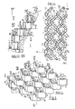
- Fig.2, Fig.2a shows the floor plan of a free-standing plant wall made of angular stones 1 crossed in pairs, which are alternately layered and laid in pairs in the longitudinal direction 29 and in the transverse direction 30 to form hollow shapes.
- the upper 27 and lower cross-sectional areas 28 are interlocked with one another at the intersection points 51 by means of flat, rectangular recesses 34 with an incision depth of approximately 6 mm.
- the base plates 10 serve as further bracing of the angle stones, each closing the laterally projecting stone projections downwards and preventing the soil for planting terraces 7 from falling through.
- Fig.3, Fig.3a shows the floor plan of simply crossed, interlocking angle blocks 1 for vertical slope attachment.
- the interlocking of the stacked stone layers is cut out from the upper and lower cross-sectional areas by cutouts 34, which are complementary to each other, perpendicular to the leg edges 23 and 24 in the area of the intersection points 51 of the central leg axes 32, the incision width being slightly wider than the leg width 19, thus approximately 7 cm is wide, with an incision depth of approx. 6 mm.
- Simply crossed layers can be attached to an existing base 74 as a half-stone wall. Above the base 74, the wall width can be doubled to the entire stone width and can be placed on and further developed as a double crossed layer as shown in FIG. 2.
- Fig.3b shows the perspective of a vertical slope attachment of Fig.3a.
- the angle stones 1 are installed in the wall structure with an offset in the longitudinal direction 29 of half a stone length per layer.
- the leg edges 18 which spring back towards the butt joint 26 form planting terraces 7 above the projections underneath.
- the bottoms of the respective projections are closed by bottom plates 10 which run with their front plate edges complementary to the adjacent edges of the angle stones 1 and touch them at least with half their plate thickness. To the rear, they overlap the butt joint and parts of the leg edges of the lower stones with their rebates.
- the base plates 10 also act as stiffening elements and horizontal disks between the adjacent angle stones.
- angle blocks 1 can be closed with filler blocks 57 to form hollow supports and cast into reinforced concrete supports.
- horizontal sheet piling 59 made of railway sleepers or concrete slabs can be used as a design variant in order to retain earth.
- the two lower layers are attached to an existing wall base 74, on the surface of which a second row of angle stones can be placed.
- Fig.3c shows a section of the vertical section I-I with two planting days closed at the bottom by base plates 10 with the rear fold 25 of the base plates 10.
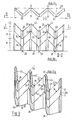
- Fig. 4a shows the perspective of an embankment sheeting made of offset angular stones 1 which are equipped on their upper and lower transverse edges with complementary U-shaped incisions 34 or elevations 86.
- the series of groove-shaped profiles begins on the leg axis 31 as a depression 34 with a width that is slightly wider than the stone width, here about 6.2 cm. Alternating to the left and right, there is an increase of 6.0 cm in width and then a depression, etc. to the end of the leg.
- the angle stone of normal size of approx. 36.5 cm leg length and 6 cm leg thickness, there are two elevations of approx. 2.5 cm height and three depressions per upper leg edge, as shown at the upper transverse edge of the top row.
- the lower transverse edge has three elevations and two depressions and thus snaps into the upper transverse edge of the same stone underneath, e.g. the third row, a.
- the crossing and engaging of the central recesses of two angle stones is shown between the first and second row, where the second row is turned upside down, the butt joints of the bottom row are bridged in the middle of the stone and this interlocking on the support results in a shear-proof connection in the longitudinal and transverse directions .
- the friction of the horizontal joints, their anchoring and abutment against earth pressure are increased.
- the load result from earth pressure and wall weight is influenced favorably.
- Fig. 4b shows a vertical section to Fig.4a and 4c.
- the individual stone terraces I to V can be planted.
- the incisions of the upper and lower transverse edges in the bed joints between the first and second layers and the fourth and fifth layers snap into one another, while the third and fourth layers each cut into the center of the stone 31 on the elevations below them two touching leg tips sits and bridges their butt joint and holds together.
- the angle stones which are open on the mountain side, form jagged terrace edges towards the valley side, behind which the grown soil is present without the hindrance of a second wall which is customary for closed hollow bodies. This allows the planting days to be well moistened and rooted from the slope. In addition, the omission of a wall leads to a 100 percent material and weight saving compared to closed hollow bodies.
- the angle stones can also be shaped and cast into inclined reinforced concrete columns by forming closed hollow columns according to Fig.3, Fig.3a and Fig.3b.
- the flattest slope slope of about 37 degrees is achieved with the type of dislocation used from layer II to III and from layer III to IV.
- the slope is vertical between the first and second layers, and the inclination is 62 degrees between the fourth and fifth layers.
- Flatter slopes can be achieved by placing the stone layers directly on the site and no longer on an underlying stone layer. The disadvantage of this is that the stones can no longer be interlocked.
- Fig.4, Fig.4c shows the floor plan of layered, interlocking and interlocking angle stones 1 for slope protection.
- the upper edges of the 25 cm high planting terraces are marked with the numbers I-V and correspond to the floors of fig.4a and 4b.
- rows of dowel holes 35 can also be inserted at uniform intervals on the top and bottom surfaces of the angle blocks 1.
- Cross dowels 36 can be anchored to one another in a shear-resistant manner using rod dowels 36.
- Fig. 5a shows the perspective of a slope or garden wall made up of angle stones 1 and closed on the front.
- the individual layers are offset so that the front legs in the longitudinal direction 32 of the wall are rotated by 180 degrees in each layer (Fig.5f), so that the legs of one layer point to the right and in the next layer to the left, while theirs to the rear facing legs stand on each other.
- Fig.5f the front legs in the longitudinal direction 32 of the wall are rotated by 180 degrees in each layer
- Fig.5f the legs of one layer point to the right and in the next layer to the left, while theirs to the rear facing legs stand on each other.
- the layer on top bridges the joint 26 below with its stone center 31.
- plate-shaped half stones 9 are inserted between two leg tips 13. This way, closed cavities can be formed, be it to reinforce the wall stiffness to reinforced concrete columns or to close the rear wall surface for a free-standing installation with possible filling with concrete or earth.
- the good stability of the wall according to Fig.5a can be further improved by inserting non-rotting non-woven fabric or ground anchors between the horizontal joints of the rear legs.
- the later backfilling acts as a load on the fleece, thus increasing the weight of the heavyweight wall and counteracting the slope pressure.
- the four dowel holes 35 of a cross-sectional area with the two times two holes 35 of two stone halves below and / or above must be aligned with each other and connected with inserted dowels 36.
- the profiles 40 and recesses on the joint 26 or on the stone back 31 serve the optics and design.
- Fig.5a shows several alternatives for horizontal dowelling.
- the two upper right transverse edges show two elevations 86 and three incisions per leg symmetrical to the bisector of the leg, which form-fit engagement with the lower, complementary transverse edge profiles can be brought, wherein the edges of the elevations 86 extending transversely to the outer edges 18 can be designed with an inclination of approximately 5 to 45 degrees to the vertical.
- the elevations 86 can run as profile edges 40 ° between the transverse edges 23 and 24 along the outer and / or inner wall surfaces.
- the third transverse edge from the right shows transverse grooves 34 in the middle of the leg as already described in FIGS. 3 and 4. If the lower transverse edges are also provided with transverse grooves 34, two superimposed grooves can be positively engaged with one another by means of complementary rectangular dowels 87 or H-shaped profile pieces 88. Correspondingly, dowels with a dovetail-shaped 89, square 106 or round layout 105 with complementary recesses can be brought into positive engagement and thus aligned with each other in the longitudinal and transverse directions and dowelled securely.
- Prism-shaped dowels 90 can also be integrally formed on the lower edge of the leg and brought into positive engagement with the recesses 90 ° of the upper leg edges which are complementary thereto, cf. Fig.5a bottom right.
- the flange of the H-profile piece 88 can dip into the upper transverse groove 34 and, with its parallel flange sections, align the walls of the stone placed thereon parallel to the lower stone .
- Fig. 5 Fig.
- FIG. 5b shows the floor plan of the first (II) and second (II-II) layers, which are drawn one inside the other and also show several alternative transverse edge profiles: transverse edges with incisions 34, with elevations 86, with hollow chambers 91 and with dowel holes 35 Also shown is an isosceles right-angled cover plate 104 with the cutouts 86 ° on the short sides of the triangle, which can be brought into positive engagement with the elevations 86 of the angle stones, and with the aid of which stools and tables can be produced.
- the cover plate 104 can be extended on each of the three sides, the cutouts appearing as 86 ° square cuts.
- the corresponding angle plate 104 ° is equipped with two prongs on each of the two short triangle sides.
- Fig. 5c shows the perspective of an angle block 1 with groove-shaped profiling 86 and 25 on the transverse edges.
- the elevations 86 are grooved along the central axis 32 of the leg, while the depressions 86 are provided with additional spring-shaped designs 25.
- the upper edge surface can be brought into positive engagement with the complementary lower edge surface, the double toothing 86 + 25 resulting in a shear-proof positive locking in the longitudinal and transverse directions.
- Fig. 5d shows three different cross-sections of the angle block 1, which, as an alternative to the full wall thickness, bring about statically justifiable cross-sectional reductions and thus material and weight savings. This allows special material properties and production methods to be taken into account.
- the uppermost U-shaped cross section 93 shows a one-sided slender web with two parallel flange sections, while the I-shaped cross section 92 is equipped with a central web. Both cross sections can e.g. poured into concrete or plastic or glued together from wood.
- the webs can be additionally reinforced by vertical ribs.
- the horizontal reinforcements of the transverse edges form grip strips, with the help of which the angle stones 1 can be carried more easily and can be moved better.
- the hollow profile 91 has parallel, closed outer walls and internal, tubular cavities and is suitable for extrudable, plastically processable, post-curing materials such as ceramics.
- Fig. 5, fig. 5e shows two rod dowels 36 connected to one another by a plate 37.
- the plate of approx. 30 x 120 mm acts as a tension plate for bridging butt joints as well as a spacer for easier assembly and consists of sheet metal of approx. 2.5 mm thickness or of plastic with two Hole cut-outs for the rod dowels 36.
- the plate 37 ° can also be provided with three or more holes in a polygonal manner, for example in order to insert a vertical reinforcing iron 43 through one of the holes, so that reinforcing ribs 58 can be formed by stripping and casting the corners (see Fig.5a and 5b).
- Fig.5f shows a laying sketch for the wall shown in Fig.5a.
- the bottom layer points with its front legs to the west and in the second layer to the east, while its north-facing legs are vertically one above the other.
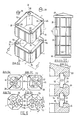
- Fig. 6a shows the perspective of a pillar construction made of angle stones 1.
- Each pair of angle stones touching in pairs with their thigh tips 13 at the joint 26 form a square plan with an enclosed cavity.
- the next layer is rotated by 90 degrees so that butt joints 26 are bridged by the stone centers 31 of the next layer.
- ring dowels 39 are inserted into the complementary groove-shaped recesses 38 in order to achieve both horizontal and vertical dowels.
- the outer surface of the angle stone is provided with cove-shaped depressions 40, which give a structured appearance as shadow gaps of the column according to Figs. 6a and 6b or the wall according to Fig.
- the edge 56 is chamfered, so that in the installed state the horizontal joint lies approximately 6 mm behind the stone surface, and horizontal shadow grooves are formed.
- Fig.6b shows the view I-I of a finished, in the manner of Fig. 6a, about 1.10 m high pillar with floor 55 and cover plate 41, as it can be used as a garden and gate pillar or storey high in building construction.
- Fig.6c shows the cross section through a pillar according to Fig. 6b with cover plate 41, base plate 55 and an additional (possible) intermediate plate or ring 54 which can be inserted for design reasons.
- the plates or intermediate rings provided with grooves 52 bridge the vertical butt joints with their stone centers according to the same principle of the wall structure.
- the rebates 25 of the multi-wall sheets are recommended but not absolutely necessary. They can prevent critical material weakening of the grooved molded parts.
- Fig.6e shows the floor plan of a square column, which is assembled from two angle stones 77.
- the diagonal strut 78 connects the two angular stone tips and gives the stone greater rigidity and better stability, which makes assembly easier and faster.
- the reinforcement and concreting of the hollow chambers also meet special stability requirements such as those for free-standing pillars and columns. be demanded, fulfilled.
- the semi-circular recess 79 of the strut 78 results in the assembly of two angle stones 77 in the middle of the plan a circular recess that can be reinforced vertically and grouted with mortar.
- the remaining hollow chamber can also be filled continuously.
- Fig.6f shows the next layer of the floor plan of Fig. 6e of a square column, which is assembled from two angle stones 77.
- the butt joint 26 underneath is bridged with its stone center 31.
- An additional, alternative strut 80 in the transverse center plane 31 gives the hollow block 77 additional strength.
- Fig.6g shows the layout of a regular octagon, which is composed of four identical segment stones 82.
- the vertical butt joints between the stones 82 form a cross shape, which is twisted by half a stone from layer to layer in that the butt joints 26 of one layer are bridged by the stone centers 31 of the next layer (Fig. 6h).
- the circular recesses on the axes of the butt joints 26 and the stone centers 31 form tubular cavities which run vertically through the twisted stone layers.
- Fig.6h shows the octagonal floor plan of the layer next to Fig.6g.
- the lateral surface can also be subdivided into smaller surface sections, so that any polygonal floor plans up to the round column are possible.
- Hexagonal and twelve-sided floor plans can be formed from three segment stones each, as shown in Fig.11e.
- the segment stones 69 and 70 can be designed as hollow body stones such as 82 and 85.
- Fig. 7, Fig. 7a shows the cruciform plan II-II of a planting tower made of angle stones 1 butted in pairs on the back 14 with a butt joint 26 in the east-west direction.
- Two of the four right-angled chambers are formed by the inner leg edges 17 and two chambers by the outer leg edges 18, i.e. of the 90 degree gaps.
- the chambers can be filled vertically with earth by diagonally inserted floor plates 5 and 5 ° partitioning the openings in a terrace-like manner and holding back the earth core 8 in the corner of the chambers.
- Fig. 7, Fig. 7b shows the following layer of the cruciform ground plan I-I of Fig. 7a, but the angular stones touching in pairs are rotated by 90 degrees, so that their joint joint 26 now runs in a north-south direction.
- the 90 degree rotation in each layer causes each butt joint 26 in the next layer to be bridged by two angle stones in the middle 31 of the stone.
- a multi-layer cross column can be loaded and calculated like a homogeneous cross-shaped profile. Additional bonding between the layers is achieved by anchoring with H, 64, U, 65 or Z profile pieces 65 °, which are fitted in the middle of the leg in matching groove-shaped recesses transverse to the central axis of the leg and thus align the superimposed legs with each other.
- the alternative use of the concealed rod dowels 36 can be dispensed with.
- the other joint designs F-1 to F-15 are also suitable for this type of transfer.
- dowel holes 35 or 91 per block are provided for alternative dowelling of the horizontal joints. They match the two by two holes 35 of the pair of legs below and above, so that layers can be connected with eight rod dowels 36. To simplify assembly, double-rod dowels with a tab 37 can also bridge the butt joints 26.
- the Fig.7c shows the view III-III of two layers of cross-shaped offset stones 1 with built-in and filled floor slabs 5.
- the plantable terraces 7 each extend in their inclined surface from the outer upper transverse edge 23 of the lower to the lower transverse edge 24 of the upper floor plate 5.
- Fig.7d shows the perspective of the cruciform plant tower with plant days in the bottom and top layers.
- Layers 2-4 show the stone layers, each rotated by 90 degrees, a butt joint 26 being bridged by a stone center 31.
- the horizontal rod dowels 36 which are embedded in the side in dowel holes 35 of the stone walls, serve as supports 49 for the floor panels 5 and 5 °.
- a corner stone 3 with a pointed upper transverse edge is placed on top of the normal corner stones in Fig.7e.
- FIG. 8a shows the floor plan of a plant wall made of three pairs of wall-high angle elements screwed together in the transverse direction 31 by means of screws 46, which are placed next to one another in the longitudinal direction 29 to form hollow chambers that can be filled are and which touch with their free leg tips 13 at the joints 26.
- cubic concrete or rubber blocks 44 are inserted as spacers, so that a space of any size, shown here with about 8 cm, can be created.
- the firmly anchored and screwed spacers 44 form the supports for an irrigation line 45 laid in the longitudinal direction, which with one nozzle per chamber permits automatic moistening of the hollow chambers.
- the individual angle element 2 which is laid in the transverse direction 30 on the left, closes off the wall and is connected to the free legs of the associated angle stones with the aid of steel angles 47 and screws 46 standing at a corner.
- the footplate 103 formed on the floor points into the interior of the wall and receives a high level of stability due to the earth load sitting on it.
- the right end of the wall is closed off by terrace slabs 5.
- recesses can also be left out in the back 14 of the angle elements 2 for the implementation of horizontal irrigation and pull pipes 45.
- Fig.8b shows the perspective of the floor plan of Fig.8a, the wall made of approximately 1.2 m high corner elements.
- the leg length 20 is approx. 40 cm, the thickness 19 approx. 7 cm.
- the upper transverse edges run from their thigh tips to the transverse central plane 31 in a pointed shape.
- the cross-sectional areas are chamfered in the shape of a gable roof from the thigh central axis 32 raised as a ridge line.
- the two parallel buckling walls can also be made of angle stones 1 of approx. 30 cm Height in the bandage according to Fig.1, Fig 1e.
- the pointed wall crown can be formed with angle stones 2 as shown in Fig. 7, Fig. 7e.
- the zigzag-shaped, upper wall crown is offered as an additional design element, not least to make the character of the soundproofing, privacy wall and security walls more friendly.
- the wall crown can of course also consist of rounded, softly curved upper transverse edges 23.
- a soft earth filling e.g. from earth substrate act as a buffer and vibration damper between the corner elements.
- the angle elements 2 can be built up to heights of approx. 4 m and above by anchoring them in concrete foundations, and possibly additionally with rigid bracing and multiple screw connections between the elements against horizontal forces.
- the wall crown After filling the hollow chambers with soil, the wall crown can be planted in an ecologically valuable and visually mitigating manner to mitigate the safety character of the wall.
- FIG.8b shows on the left two angle stones 2 with foot plates 103 formed parallel to the lower transverse edge surface, which offer the angle elements 2 additional stiffening.
- the diagonal 22 extending between the leg tips 13 and the leg edges delimit the footplate 103 statically operatively connected to the leg walls.
- Foot plates 103 In connection with loads on the foot plates 103, in the form of earth or other weights such as Plant troughs, the walls of the corner elements appear clamped on the floor. This leads to the fact that with increasing loads on the foot plates, the stability of the angle stones increases, and thus freely positioned angle elements with a foot plate can be higher than those without a foot plate 103. Foot plates should therefore preferably point inside a wall filled with earth, such as in the outermost, left-hand corner stone shown in Fig. 8, in order to take advantage of any existing earth loads to increase stability.
- a stone with cover plate, stool, table segment or half of a hollow column can be used.
- the halves can be completed into cuboid bodies, cf. Fig.5, Fig.5b.
- the stackability of angled stones is basically retained even with the foot and cover plate molded on one side, however the stack increases by the thickness of the foot plates.
- Fig. 9a shows the perspective of a garden wall made of angle stones 3 to the floor plan of Fig. 9c and the view of Fig. 9b, the bed joints 42 of which are not horizontal, but from their outer leg tips 13 at an acute angle to the center of the stone 31 or descending.
- Moving in association with bridging the butt joints 26 by stone centers 31 is achieved by tilting the stones of the next layer by 180 degrees and once with their tip down into the recesses of the underlying layer, or in the next layer with their tip up and with their stone center 31 cover the butt joint 26 below.
- the initial layer should be provided with a horizontal bed joint 33 for better positioning.
- the individual layers can be contrasted in color and, with their up and down movements, as well as the projections and recesses, create a lively design.
- Fig.9b shows the view II-II of Fig.9a with staggered butt joints 26 of the staggered angular stones 3 with the parallel, acute-angled bearing joints 42.
- the upper 23 and lower transverse edges 24 run parallel to each other at a distance of their height 21.
- the transverse edges 23 and 24 can of course also be rounded in a wave shape.
- Fig.9c shows the top view I-I on the top layer of Fig.9b with the ridge edges in the middle of stone 31.
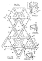
- Fig.10 shows the perspective of a 60-degree stone 61 with a leg length 20 of 45 cm, a height 21 of 25 cm, a diagonal 22 of 55 cm, and a thickness 19 of 7 cm.
- Fig.10b shows the floor plan of two hexagonal planting columns pushed into the middle of the leaf, each of which consists of three 60 degree stones 61 which are "staggered".
- the 60-degree gaps and butt joints 26 between the angle stones 61 are bridged in the next layer with the stone centers 31, so that a composite is created according to the principle of staggered butt joints.
- the open sides of the individual chambers are formed by tier plates 5 ° to plant terraces, which hold the earth core 8 in the corner of the niche.
- the three angle stones attached to the openings on the lower leaf edge are only one layer high and serve as upstream plant beds 75.
- the leg edges 18 outside the leg center axis 32 are symmetrical to the leg bisector 72, so that the projection 62 at the leg tip BM ° and leg back AM on the plane of the leg center axis 32 is of equal width.
- the back of the leg 14 can be equipped both with a smooth surface and with a notch 76, the edges of which run parallel to the inner leg edges 17.
- Fig.10, Fig.10C shows the perspective of a homogeneous angle stone container 73 in which the floor plate 5 is formed.
- the greater strength and rigidity of such a closed shape compared to the open angle block allows a certain amount of material to be saved. However, the shape cannot be stacked one inside the other.
- Fig.10, Fig.10d shows the perspective of an angle block 1 whose leg tips 13 run obliquely between the upper 27 and lower transverse edge 28, so that the legs of the lower transverse edge 28 are shorter than at the upper transverse edge 27.
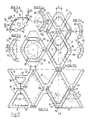
- Fig. 11a shows in the bottom two rows of the sheet two 60 degree angle stones 61, which are connected to each other on their backs 14 similarly as in Fig. 8.
- an angle block 61 of the second position sits with its center 31 over the butt joint 26 below. In this way, zigzag-shaped walls can be erected as shown in Fig. 1 (wall type A-1).
- FIG. 11b shows, in an extension of the axis 31, the intersecting angle stones 61, which are hooked together in the region of their leg bisectors 72 by cutouts 34.
- the 60 degree angle stones 61 can only be pushed parallel to the wall transverse direction 30 with butt joints 26.
- the butt joints 26 on the stone back and thigh tips 13 can be bridged by tabs 37 and rod dowels.
- the base plates 10 ° close off the diamond-shaped projection on one or both sides in the region of the butt joints 26, thereby forming plant terraces and additionally interlocking the wall.
- Fig. 11, Fig. 11c shows on the right leaf edge a square 68 and a rounded 68 ° filler stone, which alternatively serve as a closure for the otherwise open plant terraces 7.
- the cavity that has been shut off in this way can be concreted, for example, as a support.
- Fig. 11, Fig. 11d shows a regular, equilateral hexagon in which a layer consists of three isosceles third plates 69, which have an inside angle of 120 degrees and form an angle of 120 degrees at the joint with the neighboring plate.
- Each leg of the hexagon-third plate is with its outer edges 18 symmetrical to the leg bisector 72, so that the profiles of the leg ends up to the leg axis 32 at the tip 13 and the leg back 14 are the same width and depth.
- the vertically superimposed joints 26 and stone back 31 therefore act in the view as identical sections of a vertically continuous shadow gap.
- Fig.11e shows an alternative to the third plate 69, a third hollow block 85 in the form of a piece of cake in the manner of the segment stones 82, shown in FIGS. 6, 6g and 6h, with circular cutouts in the transverse central plane 31, with two semicircular ones Recesses on the butt joint axis 26 and with a recessed circular segment at the stone tip.
- the widened footprint of the hollow block 85 in relation to the third plate 69 enables faster assembly and greater initial stability of a column created therefrom.
- the third plate 70 can also be designed with a curved surface as shown in FIG. 11f.
- Fig.11, Fig.11f shows the third plate 70 with two curved lateral surfaces which are symmetrical to the leg bisector 72.
- hexagonal columns made of thirds plates 69 or 85 round columns are made of three thirds plates 70 per layer with a curved outer surface by alternating layers Stone centers 31 are placed on the joints 26 below.
- the three third panels 70 form with their curved outer surface a circular outer edge, which is provided with six groove-shaped depressions, ie in the installed state with six vertical shadow gaps.
- Fig. 12, Fig.12a shows the plan of a plant trough, approximately 90 x 120 cm edge length, the two left corners of isosceles angle stones 1 and the two right corners of isosceles angle stones 98.
- Between the acute-angled leg ends complementary shaped V-shaped plates 99 of any length are inserted.
- thickenings can be formed on the plates 99 with an angular 100 and a round cross section 101.
- the reinforcements 100 and 101 at the joint can be designed as ornamental design elements.
- the two unequal leg angle stones 98 form with a short and a long leg and an intermediate plate 99 the right end of the plant trough.
- a second layer II covers the lower butt joints by turning the angle blocks and with their long legs covering the short legs underneath and vice versa, short legs come to rest on long legs.
- a wall structure with offset butt joints is created.
- the octagonal or round profiles 95 and 96 in Fig.12f also create shear-proof teeth in the longitudinal and transverse directions between angle blocks 98 and plates 99.
- Fig.12a to form stable corners from angle blocks 1 and 98 and to insert form-fittingly connected panels 99 between them, can be used as a building system for the construction of entire buildings.
- angle slabs can be transported to a construction site, standing or lying, and can be moved on site with hoists. Without any mounting brackets that are otherwise necessary for wall panels, the angle elements are free and tilt-proof on their base.
- the wall plates 99, with the corner elements 1 and 98 positively connected by tongue and groove, are already leaning on one side of an angle element in the assembled state. After a second angle element has been connected to the second, still open plate end, the plate element 98 is clamped between two angle elements, so that it does not tip over.
- the support of ceiling panels on corner and wall panels acts as a stiffening disc and effectively integrates the wall panels into a building system.
- Fig. 12b shows on the left the floor plan of a rectangular column which can be assembled from two identical, unequal-angle corner stones 98, the butt joints 26 of which in the following layer are "overturned” by bridging two identical stones 98 from their stone back 31.
- the rest of the description corresponds to the square column presented in Fig.6, Fig.6a.
- Fig.12, Fig.12c shows the view of the two layers I-I and II-II shown in Fig.12a, the right end of the plant trough.
- the side parts of the planting trough can either be placed on the ground or on the corresponding floor slabs and can be positively connected to them with complementary joint profiling.
- Fig.12, Fig.12d shows the floor plan of a sheet pile corner consisting of two spaced-apart angle blocks 1, which are stackable in height, with sheet piles pushed in between, e.g. railway sleepers and the like.
- the angle stones can be screwed to the legs or the stone back and the sheet piling in between can be clamped in between.
- the insertable sheet piles 59 and thus the distances between the corner elements can be correspondingly long.
- the right, lower square 97 can alternatively and in the contours be made congruent to two touching angle stones 1 as a closed trough stone 97, which is provided as an uneven octagon, each with an incision 34 on the bisector of the long sides.
- the corner stones above are equipped with two octagonal button-shaped elevations 95 and 95 ° recesses per side of the leg, which are designed to be complementary to each other.
- the two left-hand angled blocks are shown with round profiles 96 and recesses 96 ° of their transverse edges. Both the round and the octagonal "button profiles" enable dowel-proof dowelling of the horizontal joints in the longitudinal and transverse directions.
- the upper left square formed from two angle stones 1, shows a diagonal joint of two cover plates 104 connected to the angle stones.
- the button-like elevations of the angle stones 95 ° and 96 ° engage positively in the complementary recesses of the cover plates.
- Fig.12, Fig.12f shows the view of a pyramid which is formed from three angle stones 1 standing on the feet. In each case there is an angled stone with "spread legs" on the “back” of two angled stones underneath that touch the "feet". If the base is widened accordingly, the pyramid can be increased to approx. 10 layers and processed into ornamental walls and sculptures. The joints are glued and / or dowelled.
Landscapes
- Engineering & Computer Science (AREA)
- Life Sciences & Earth Sciences (AREA)
- Mining & Mineral Resources (AREA)
- Civil Engineering (AREA)
- Structural Engineering (AREA)
- General Life Sciences & Earth Sciences (AREA)
- Paleontology (AREA)
- General Engineering & Computer Science (AREA)
- Environmental Sciences (AREA)
- Environmental & Geological Engineering (AREA)
- Architecture (AREA)
- Revetment (AREA)
- Cultivation Receptacles Or Flower-Pots, Or Pots For Seedlings (AREA)
- Emergency Lowering Means (AREA)
- Stringed Musical Instruments (AREA)
- Joining Of Building Structures In Genera (AREA)
- Conveying And Assembling Of Building Elements In Situ (AREA)
- Ladders (AREA)
- Fencing (AREA)
- Ignition Installations For Internal Combustion Engines (AREA)
- Pinball Game Machines (AREA)
- Valve Device For Special Equipments (AREA)
- Forms Removed On Construction Sites Or Auxiliary Members Thereof (AREA)
- Reinforcement Elements For Buildings (AREA)
Applications Claiming Priority (2)
| Application Number | Priority Date | Filing Date | Title |
|---|---|---|---|
| DE8809862U | 1988-08-02 | ||
| DE8809862U DE8809862U1 (de) | 1988-08-02 | 1988-08-02 | Bausatz aus ineinandersteckbaren Winkelelementen |
Publications (3)
| Publication Number | Publication Date |
|---|---|
| EP0357950A2 true EP0357950A2 (fr) | 1990-03-14 |
| EP0357950A3 EP0357950A3 (en) | 1990-03-28 |
| EP0357950B1 EP0357950B1 (fr) | 1996-05-01 |
Family
ID=6826570
Family Applications (2)
| Application Number | Title | Priority Date | Filing Date |
|---|---|---|---|
| EP89908690A Expired - Lifetime EP0428563B1 (fr) | 1988-08-02 | 1989-08-01 | Ensemble d'elements de construction en coin emboitables |
| EP89114228A Expired - Lifetime EP0357950B1 (fr) | 1988-08-02 | 1989-08-02 | Ensemble d'éléments de construction en coin emboîtables |
Family Applications Before (1)
| Application Number | Title | Priority Date | Filing Date |
|---|---|---|---|
| EP89908690A Expired - Lifetime EP0428563B1 (fr) | 1988-08-02 | 1989-08-01 | Ensemble d'elements de construction en coin emboitables |
Country Status (8)
| Country | Link |
|---|---|
| EP (2) | EP0428563B1 (fr) |
| AT (1) | ATE137552T1 (fr) |
| AU (1) | AU3988789A (fr) |
| DE (2) | DE8809862U1 (fr) |
| DK (1) | DK17991A (fr) |
| ES (1) | ES2088881T3 (fr) |
| GR (1) | GR3020694T3 (fr) |
| WO (1) | WO1990001597A1 (fr) |
Cited By (1)
| Publication number | Priority date | Publication date | Assignee | Title |
|---|---|---|---|---|
| EP0595193A1 (fr) * | 1992-10-30 | 1994-05-04 | Impresa Concari Prefabbricati Di P. Concari | Remblai comportant des éléments préfabriqués, collaborants et assemblables en particulier pour des constructions routières ou ferroviaires et son procédé de réalisation |
Families Citing this family (10)
| Publication number | Priority date | Publication date | Assignee | Title |
|---|---|---|---|---|
| US4920712A (en) * | 1989-01-31 | 1990-05-01 | Stonewall Landscape Systems, Inc. | Concrete retaining wall block, retaining wall and method of construction therefore |
| GB8929298D0 (en) * | 1989-12-29 | 1990-02-28 | Vidal Henri | Facing system |
| DE4027517A1 (de) * | 1990-08-30 | 1992-03-05 | Winfried E Scholta | Formstein |
| CA2146345C (fr) * | 1992-10-06 | 2001-01-09 | Dick J. Sievert | Bloc de maconnerie en materiau composite |
| TW316939B (fr) * | 1995-06-07 | 1997-10-01 | Keystone Retaining Wall System | |
| AU711224B2 (en) * | 1995-12-21 | 1999-10-07 | Ultrafloor Pty. Ltd. | Suspended flooring system and method for constructing same |
| ITSP990011A1 (it) * | 1999-12-15 | 2001-06-15 | Luciano Bertella | Impianto del vigneto in parete. |
| US20130333287A1 (en) * | 2012-06-13 | 2013-12-19 | Van M. Kassouni | Planter assembly |
| DE102020120369A1 (de) | 2020-08-03 | 2022-02-03 | Christoph Stein | Element zum Bau eines Formteils zur Errichtung einer Böschungsbefestigung etc. und Verfahren zur Errichtung einer Böschungsbefestigung etc. |
| DE102021211603A1 (de) * | 2021-10-14 | 2023-04-20 | Rainer Tamme | Garteneinrichtung |
Family Cites Families (5)
| Publication number | Priority date | Publication date | Assignee | Title |
|---|---|---|---|---|
| US3444694A (en) * | 1967-10-25 | 1969-05-20 | Leon Frehner | Curvilinear terrace construction and planter blocks and methods therefor |
| CH606680A5 (fr) * | 1976-08-18 | 1978-11-15 | Roman Buschor | |
| DE3233014A1 (de) * | 1982-09-06 | 1984-03-08 | Betonwerk Augustin, Bau-Ing. Lothar Augustin, 7553 Muggensturm | Bauelement zum erstellen eines trockenmauerwerks |
| DE3420037A1 (de) * | 1984-05-29 | 1985-12-05 | Georg 2400 Lübeck Dose | Addierbare formelemente zur begruenung |
| US4798499A (en) * | 1985-05-17 | 1989-01-17 | Kensetsukiso Engineering Co., Ltd. | Retaining panel |
-
1988
- 1988-08-02 DE DE8809862U patent/DE8809862U1/de not_active Expired
-
1989
- 1989-08-01 EP EP89908690A patent/EP0428563B1/fr not_active Expired - Lifetime
- 1989-08-01 DE DE58909672T patent/DE58909672D1/de not_active Expired - Fee Related
- 1989-08-01 AU AU39887/89A patent/AU3988789A/en not_active Abandoned
- 1989-08-01 AT AT89908690T patent/ATE137552T1/de not_active IP Right Cessation
- 1989-08-01 WO PCT/DE1989/000505 patent/WO1990001597A1/fr not_active Ceased
- 1989-08-02 EP EP89114228A patent/EP0357950B1/fr not_active Expired - Lifetime
- 1989-08-02 ES ES89114228T patent/ES2088881T3/es not_active Expired - Lifetime
-
1991
- 1991-02-01 DK DK017991A patent/DK17991A/da not_active Application Discontinuation
-
1996
- 1996-07-31 GR GR960402061T patent/GR3020694T3/el unknown
Cited By (2)
| Publication number | Priority date | Publication date | Assignee | Title |
|---|---|---|---|---|
| EP0595193A1 (fr) * | 1992-10-30 | 1994-05-04 | Impresa Concari Prefabbricati Di P. Concari | Remblai comportant des éléments préfabriqués, collaborants et assemblables en particulier pour des constructions routières ou ferroviaires et son procédé de réalisation |
| US5482408A (en) * | 1992-10-30 | 1996-01-09 | Impresa Concari Prefabbricati Di P. Concari | Embankment formed by preformed collaborating assemblable elements, in particular for road or railway constructions, and process |
Also Published As
| Publication number | Publication date |
|---|---|
| GR3020694T3 (en) | 1996-10-31 |
| EP0357950B1 (fr) | 1996-05-01 |
| DK17991D0 (da) | 1991-02-01 |
| DK17991A (da) | 1991-03-08 |
| ATE137552T1 (de) | 1996-05-15 |
| DE58909672D1 (de) | 1996-06-05 |
| AU3988789A (en) | 1990-03-05 |
| WO1990001597A1 (fr) | 1990-02-22 |
| ES2088881T3 (es) | 1996-10-01 |
| EP0428563B1 (fr) | 1996-05-01 |
| DE8809862U1 (de) | 1988-11-24 |
| EP0428563A1 (fr) | 1991-05-29 |
| EP0357950A3 (en) | 1990-03-28 |
Similar Documents
| Publication | Publication Date | Title |
|---|---|---|
| US5456555A (en) | Structural set of angle elements fitting into one another | |
| EP0170113B1 (fr) | Bloc de construction | |
| EP0319465B1 (fr) | Assortiment de pierres en béton pour murs pour construire un mur empilé à sec | |
| CA1128327A (fr) | Tirants de maconnerie | |
| EP0039372B1 (fr) | Brique moulée pour talus | |
| EP0357950A2 (fr) | Ensemble d'éléments de construction en coin emboîtables | |
| DE2519232C3 (de) | Bepflanzbare Stützmauer | |
| EP0234175A1 (fr) | Ensemble de construction pour la réalisation de murs | |
| EP0187615B1 (fr) | Jeu d'éléments pour constructions composites | |
| DE3925401A1 (de) | Bausatz aus ineinandersteckbaren winkelelementen | |
| DE2718290A1 (de) | Bauelementsystem zur erstellung bepflanzbarer mauern | |
| DE2951485A1 (de) | Bauelementsystem zur erstellung bepflanzbarer waende | |
| EP0034565B1 (fr) | Mur composé d'éléments de construction | |
| EP0024500B1 (fr) | Elément de construction en béton | |
| DE3303144A1 (de) | Bepflanzbarer werkstein und bepflanzbare wand | |
| DE2937478A1 (de) | Bauteilsatz und bauelement zur herstellung von bauwerken sowie damit gebildete mauer und verwendung zur mauerherstellung | |
| DE3406136A1 (de) | Werkstein zum errichten vertikaler waende | |
| DE19851674A1 (de) | Baustein und daraus gebildetes Mauerwerk | |
| DE2826324A1 (de) | Stuetzwand, bestehend aus einem aus beton-fertigteilen zusammengesetzten raumgitter, dessen hohlraeume mit schuettgut verfuellt sind | |
| WO2006030009A1 (fr) | Systeme d'ouvrage de maçonnerie | |
| EP0198934A1 (fr) | Elément structural pour l'édification de murs à sec, et mur construit avec de tels éléments | |
| DE29510721U1 (de) | Freistehende, bepflanzbare Wand | |
| DE19522570A1 (de) | Bauelement zum Herstellen von Flächen mit sechseckigem Grundriß gleicher Seitenlänge | |
| DE4104045C2 (de) | Verfahren zur Herstellung einer vielseitig einsetzbaren Stützwandkonstruktion zur Stabilisierung von Geländesprüngen | |
| DE3501147C2 (de) | Werkstein |
Legal Events
| Date | Code | Title | Description |
|---|---|---|---|
| PUAI | Public reference made under article 153(3) epc to a published international application that has entered the european phase |
Free format text: ORIGINAL CODE: 0009012 |
|
| PUAL | Search report despatched |
Free format text: ORIGINAL CODE: 0009013 |
|
| AK | Designated contracting states |
Kind code of ref document: A2 Designated state(s): ES GR |
|
| AK | Designated contracting states |
Kind code of ref document: A3 Designated state(s): ES GR |
|
| RHK1 | Main classification (correction) |
Ipc: E04C 1/12 |
|
| 17P | Request for examination filed |
Effective date: 19900925 |
|
| 17Q | First examination report despatched |
Effective date: 19911008 |
|
| GRAA | (expected) grant |
Free format text: ORIGINAL CODE: 0009210 |
|
| AK | Designated contracting states |
Kind code of ref document: B1 Designated state(s): ES GR |
|
| REG | Reference to a national code |
Ref country code: GR Ref legal event code: FG4A Free format text: 3020694 |
|
| REG | Reference to a national code |
Ref country code: ES Ref legal event code: FG2A Ref document number: 2088881 Country of ref document: ES Kind code of ref document: T3 |
|
| REG | Reference to a national code |
Ref country code: ES Ref legal event code: FG2A Ref document number: 2088881 Country of ref document: ES Kind code of ref document: T3 |
|
| PGFP | Annual fee paid to national office [announced via postgrant information from national office to epo] |
Ref country code: ES Payment date: 19970228 Year of fee payment: 8 |
|
| PLBE | No opposition filed within time limit |
Free format text: ORIGINAL CODE: 0009261 |
|
| STAA | Information on the status of an ep patent application or granted ep patent |
Free format text: STATUS: NO OPPOSITION FILED WITHIN TIME LIMIT |
|
| 26N | No opposition filed | ||
| PG25 | Lapsed in a contracting state [announced via postgrant information from national office to epo] |
Ref country code: ES Free format text: LAPSE BECAUSE OF NON-PAYMENT OF DUE FEES Effective date: 19970803 |
|
| PGFP | Annual fee paid to national office [announced via postgrant information from national office to epo] |
Ref country code: GR Payment date: 19980902 Year of fee payment: 10 |
|
| PG25 | Lapsed in a contracting state [announced via postgrant information from national office to epo] |
Ref country code: GR Free format text: LAPSE BECAUSE OF NON-PAYMENT OF DUE FEES Effective date: 19990831 |
|
| REG | Reference to a national code |
Ref country code: ES Ref legal event code: FD2A Effective date: 19980910 |