EP0357964A2 - Vanne proportionnelle - Google Patents
Vanne proportionnelle Download PDFInfo
- Publication number
- EP0357964A2 EP0357964A2 EP19890114404 EP89114404A EP0357964A2 EP 0357964 A2 EP0357964 A2 EP 0357964A2 EP 19890114404 EP19890114404 EP 19890114404 EP 89114404 A EP89114404 A EP 89114404A EP 0357964 A2 EP0357964 A2 EP 0357964A2
- Authority
- EP
- European Patent Office
- Prior art keywords
- pressure
- valve
- housing
- connection
- control
- Prior art date
- Legal status (The legal status is an assumption and is not a legal conclusion. Google has not performed a legal analysis and makes no representation as to the accuracy of the status listed.)
- Granted
Links
- 238000006073 displacement reaction Methods 0.000 claims description 12
- 238000007789 sealing Methods 0.000 claims description 4
- 230000000670 limiting effect Effects 0.000 description 3
- 230000001105 regulatory effect Effects 0.000 description 3
- 238000004804 winding Methods 0.000 description 3
- 238000010276 construction Methods 0.000 description 2
- 230000001276 controlling effect Effects 0.000 description 2
- 238000010586 diagram Methods 0.000 description 2
- 230000000903 blocking effect Effects 0.000 description 1
- 239000003638 chemical reducing agent Substances 0.000 description 1
- 238000004891 communication Methods 0.000 description 1
- 230000008878 coupling Effects 0.000 description 1
- 238000010168 coupling process Methods 0.000 description 1
- 238000005859 coupling reaction Methods 0.000 description 1
- 238000001514 detection method Methods 0.000 description 1
- 238000011161 development Methods 0.000 description 1
- 230000018109 developmental process Effects 0.000 description 1
- 230000001939 inductive effect Effects 0.000 description 1
- 239000007788 liquid Substances 0.000 description 1
- 230000007257 malfunction Effects 0.000 description 1
- 229910000859 α-Fe Inorganic materials 0.000 description 1
Images

Classifications
-
- G—PHYSICS
- G05—CONTROLLING; REGULATING
- G05D—SYSTEMS FOR CONTROLLING OR REGULATING NON-ELECTRIC VARIABLES
- G05D16/00—Control of fluid pressure
- G05D16/20—Control of fluid pressure characterised by the use of electric means
- G05D16/2006—Control of fluid pressure characterised by the use of electric means with direct action of electric energy on controlling means
- G05D16/2013—Control of fluid pressure characterised by the use of electric means with direct action of electric energy on controlling means using throttling means as controlling means
- G05D16/2024—Control of fluid pressure characterised by the use of electric means with direct action of electric energy on controlling means using throttling means as controlling means the throttling means being a multiple-way valve
Definitions
- the invention relates to a proportional valve of the type defined in the preamble of claim 1.
- the pressure-responsive part is of the pressure transducer or pressure sensor arranged in the magnet housing via the pressure tube which axially displaceably accommodates the magnet armature of the electromagnet with the valve housing and there via suitable bores in connection with the connection opening at which the pressure is to be recorded.
- the armature chamber is thus constantly subjected to the pressure to be regulated, so that the magnetic pressure tube must have a strength which corresponds to the load with maximum pressure.
- Proportional directional control valves in slide construction are also known (DE 28 40 831 C2), in which the control slide is assigned a displacement sensor or displacement sensor for detecting the control slide stroke.
- the control error between the actual position value and the position setpoint of the control spool corrects the control of the proportional solenoid.
- Such a proportional directional control valve is used as a volume flow or quantity control valve.
- the proportional valve according to the invention with the characterizing features of claim 1 has the advantage that the pressure tube accommodating the magnet armature is bypassed by the separate pressure channel for the pressure transducer running in the valve housing.
- the magnetic pressure tube does not need to be designed for the maximum operating pressure, but only for a pressure which is significantly lower, which can be achieved with conventional magnetic pressure tubes.
- the pressure transducer in the magnet housing is also inserted radially from the outside and an electronics housing which accommodates the pressure regulator is attached to the magnet housing in such a way that it covers the pressure transducer, the electrical components are located Signal outputs of the pressure transducer protected in the electronics housing, and the shortest signal lines are given to the pressure regulator. This almost completely eliminates external interference
- the valve according to the invention can be modified without design and only by correspondingly influencing the Control and regulating electronics control volume flows on the one hand as a volume valve and on the other hand limit or reduce pressures as a pressure valve.
- the pressure has a limiting effect. If the set pressure setpoint is reached, the output of the pressure controller has a limiting effect on the position setpoint.
- the proportional valve automatically changes from a quantity function to a pressure control function. If a maximum position setpoint is specified, the proportional valve according to the invention can work as a pure pressure control valve.
- a simple implementation of the coupling of the position controller and pressure controller is achieved according to a preferred embodiment of the invention in that the output of the position controller is connected to the proportional magnet via an amplifier stage and a limiter is provided with two inputs and one output, one input of which with the position setpoint signal and its other input is assigned the output signal of the pressure regulator and its output is connected to the setpoint input of the position controller.
- the limiter is designed such that the smallest input signal is switched through to its output. If the maximum position setpoint is specified, the output of the pressure controller controls the position control loop and the pressure control loop works as a higher-level control loop (cascade). If the maximum pressure setpoint is specified, only the position control loop works and the proportional valve has a quantity function. If the pressure setpoint is reached, the pressure control loop has a limiting effect.
- the proportional valve can be used on the one hand as a 3/2-way proportional valve with a quantity function and on the other hand as a pressure control valve with a pressure reducing function, depending on how the setpoints for the pressure and the position controller are set. Due to the separate pressure channel running in the valve housing, the pressure transducer is acted upon by the pressure at the third connection opening, which corresponds to the A connection in an N6 connection hole pattern.
- the setpoint of the position controller is selected to a maximum and the proportional valve according to the invention is thus operated as a pressure valve two applications possible. If the connecting channel between the two connection openings remains blocked and the third connection opening is connected to a hydraulic working circuit, the valve works as a by the two-edge control of the control slide Pressure control or pressure reducing valve. The pressure at the third connection opening or in the hydraulic working circuit connected to it is regulated to a predetermined pressure below the operating pressure of the pressure source. However, if the blocking of the connecting channel is released and the third connection opening is closed, only one control edge of the control slide is effective. The proportional valve works as a pressure relief valve and limits the pressure at the inlet of the first connection opening to a predetermined value.
- a fourth uncontrolled connection opening is provided in the valve housing, which corresponds to connection B in the N6 connection hole pattern, and if the pressure channel is designed to be connectable to the fourth connection opening, then the pressure sensor can also be acted upon by an external pressure. If the fourth connection opening is not occupied, it must be blocked. If it is pressurized, the connection of the pressure channel to the third connection opening must be blocked.
- the proportional valve according to the invention represents a compact and less susceptible to malfunction, which can be used with various functions, such as volume flow control, pressure control and pressure limitation, as a pilot and as a main control valve. Double functions, such as volume flow control with pressure limitation, are possible.
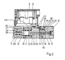
- the proportional valve shown in longitudinal section in FIG. 2 has a valve housing 10 with a standardized hole pattern (N6) to which a magnet housing 11 is flanged axially.
- a radially projecting electronics housing 12 is attached to the side of the magnet housing 11.
- the valve housing 10 has an axially extending central bore 13, in which three radial control bores 14, 15, 16 open, which lead to three connection openings 17, 18, 19.
- the control bore 15 (FIG. 4) with an associated connection opening 18 is shown in FIG. 3, rotated through 90 ° in the plane of the control bores 14 and 16.
- the connection opening 17 in Fig. 3 is rotated into the plane of the illustration.
- FIG. 4 The control bore 15 with an associated connection opening 18
- the first connection opening 17 is provided for connection to a pressure source (P), the second connection opening 18 for connection to a relief chamber (T) and the third connection opening 19 for connection to a hydraulic working circuit (A).
- the first control bore 14 and the third control bore 16 are connected to one another by an axial transverse bore 20, which is introduced from the end face of the valve housing 10 and connects two radial extension sections 58, 59 of the control bores 14, 16 extending beyond the central bore 13.
- the transverse bore 20 can be blocked or released by means of a sealing screw 21.
- a pressure channel 22 also opens into the third control bore 16, specifically in its extension section 59, which is shown in FIG.
- This pressure channel 22 opens at the end face of the valve housing 10 occupied by the magnet housing 11 and corresponds there with a connection bore 23 which leads in the magnet housing 11 to a pressure sensor or pressure sensor 24 which is integrated in the magnet housing 11, specifically on that of the electronics housing 12 occupied side is arranged.
- the pressure-responsive part of the pressure sensor 24 communicates with the inside of the control bore 16 via the connection bore 23 and the pressure channel 22, so that it detects the liquid pressure prevailing in the third control bore 16.
- a control slide 25 is guided axially displaceably in the central bore 13 and has two control edges 26, 27 for controlling the three connection openings 17 to 19.
- the control slide 25 is each provided with an annular groove 28-30, the annular groove 28 being enclosed between the two control edges 26, 27, the annular groove 29 adjoining the control edge 26 and the annular groove 30 adjoining the control edge 28 connects.
- Each annular groove 28-30 extends over a certain axial region of the control slide 25.
- the control slide 25 is loaded on one end face by a return spring 31 which is supported on the housing side.
- a plunger 32 On the other end face of the control slide 25 engages a plunger 32, which lies in an axial bore 33 aligned with the central bore 13 in the magnet housing 11 and is rigidly connected to the magnet armature 34 of a proportional magnet 35.
- the axial bore 33 is designed as a stepped bore with three bore sections 331, 332 and 333.
- the smallest bore section 331 in diameter receives the plunger 32 and the adjoining bore section 332 with a medium diameter receives a magnetic pressure tube 36 in which the armature 34 is axially displaceably guided.
- a displacement sensor or displacement sensor 37 is used in the third bore section 333 with the largest diameter, which closes the bore section 332 on the end face.
- the inductive displacement sensor 37 has a central bore 38, in which a ferrite core 39, which is axially displaceable with the magnet armature 34, lies.
- the electrical signal which can be removed from the displacement sensor 37 is a measure of the displacement path of the magnet armature 34 and plunger 32.
- the magnet pressure tube 36 is surrounded by a magnet winding 40 which is wound on a coil carrier 41 which is coaxially seated on the magnet pressure tube 36.
- the connections of the magnetic winding 40 (not shown) are the same as the electrical ones Connections of pressure sensor 24 and displacement sensor 37 guided into the electronics housing 12.
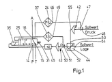
- the entire electronic control unit is accommodated in the electronics housing 12, which according to the block diagram in FIG. 1 comprises a pressure regulator 42, a position regulator 43, a limiter 44 and an amplifier output stage 45.
- the output of the output stage 45 controls the magnetic winding 40 of the proportional magnet 35.
- the output 46 of the pressure sensor 24, at which an electrical output signal proportional to the pressure in the control bore 16 is present, is fed to the actual value input 47 of the pressure regulator 42.
- An electrical pressure setpoint signal which is proportional to a predetermined setpoint pressure, is present at the setpoint input 48 of the pressure regulator 42.
- a linear relationship between the electrical pressure setpoint signal and the predetermined setpoint pressure e.g. a signal voltage of 4 V corresponds to a pressure setpoint of 100 bar.
- the output 49 of the displacement sensor or displacement sensor 37, at which an electrical output signal proportional to the control slide stroke occurs, is connected to the actual value input 50 of the position controller 43.
- the output of the position controller 43 is fed to the amplifier output stage 45.
- the output 52 of the limiter 44 which also has two inputs 53 and 54, is located at the setpoint input 51 of the position controller 43.
- the output 55 of the pressure regulator 42 is connected to the input 53, while an electrical position setpoint signal is present at the input 54 of the limiter 44, which signal is proportional to a predetermined position setpoint or control slide stroke.
- the limiter 44 is designed such that in each case the smallest input signal at its two inputs 52, 53 is switched through to its output 54.
- the electrical setpoint signals are supplied to the pressure controller 42 and the position controller 43 externally via a central connector (not shown) on the electronics housing 12.
- the power supply for the entire control electronics and the proportional magnet 35 is provided via the same connector.
- the proportional valve works as a 3/2-way proportional valve with a higher-level pressure control circuit. Proportional to the position setpoint, a control spool position results from the position control loop, which determines the opening cross sections between the control bores 14 and 16 or 16 and 15. Both control edges 26 and 27 of the control slide 25 are effective, the control edge 25 determining the opening cross section between the control bores 14 and 16 and the control edge 27 determining the opening cross section between the control bores 16 and 15.
- the pressure in the control bore 16 is detected by the pressure sensor 24.
- the proportional valve operates with a quantity function, ie it sets a volume flow in the control bore 16 corresponding to the spool stroke, which flows into a working circuit A via the connection opening 19.
- the position setpoint is specified such that the pressure setpoint in the pressure controller 42 is reached before the position setpoint in the position controller 43, the output of the pressure controller 42 acts on the setpoint input 51 of the position controller 43 - since the limiter 44 switches the smallest input signal through to its output 52 - and limits the spool stroke and thus the pressure in the Control bore 16.
- the proportional valve has now changed from its quantity function to a pressure control function.
- the proportional valve Since the input signal with the lowest value dominates at the limiter 44, it is of course also possible to have the proportional valve operate as a purely pressure valve. For this purpose, only a maximum position setpoint is to be specified at the input 54 of the limiter 44, which is above the signal voltage with respect to the size of the electrical setpoint signal, which is specified by setting the pressure setpoint at the pressure regulator 42. In this case, only the output signal of the pressure regulator 42 acts on the position regulator 43 and the setting of the control slide 25 takes place in accordance with the desired pressure in the control bore 16.
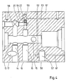
- FIG. 4 the valve housing 10 'of the proportional valve is shown enlarged in a slightly modified version.
- bores, channels and connection openings correspond to those in FIGS. 2 and 3, they are given the same reference numerals.
- a fourth, but uncontrolled, connection opening 56 is provided in the valve housing 10, which is located at the location of the connection B in the N6 hole pattern.
- the connection opening 56 delimits a blind bore 57 which is connected to the pressure channel 22 via a total of three connecting bores 61, 62, 63.
- the connecting bores 61 and 63 are made as blind bores from one end face of the valve housing 10 and are closed there.
- the connecting bore 61 penetrates the blind bore 57 and the connecting bore 63 the radial extension section 59 of the control bore 16.
- the two connecting bores 61 and 63 are connected to one another by the connecting bore 62, which is radially introduced as a blind bore and is closed at the end and which penetrates both connecting bores 61, 63.
- the connecting bore 62 runs offset to the central bore 13 and does not cut it.
- the connecting bore 63 is placed in such a way that its mouth in the radial extension section 59 is close to the mouth of the pressure channel 22.
- a plug 64 inserted into the extension section 59, the outlet points of the pressure channel 22 and the connecting bore 63 can be blocked off from the control bore 16 or the central bore 13.
- the pressure sensor 24 can thus be subjected to an external pressure present at the fourth connection opening 56. If pressure detection at the other two connection openings 17, 19 is desired, the plug 64 must be removed and the fourth connection opening 56 closed.
Landscapes
- Physics & Mathematics (AREA)
- Fluid Mechanics (AREA)
- General Physics & Mathematics (AREA)
- Engineering & Computer Science (AREA)
- Automation & Control Theory (AREA)
- Control Of Fluid Pressure (AREA)
- Servomotors (AREA)
- Magnetically Actuated Valves (AREA)
Applications Claiming Priority (2)
| Application Number | Priority Date | Filing Date | Title |
|---|---|---|---|
| DE3829992A DE3829992A1 (de) | 1988-09-03 | 1988-09-03 | Proportionalventil |
| DE3829992 | 1988-09-03 |
Publications (3)
| Publication Number | Publication Date |
|---|---|
| EP0357964A2 true EP0357964A2 (fr) | 1990-03-14 |
| EP0357964A3 EP0357964A3 (fr) | 1991-02-06 |
| EP0357964B1 EP0357964B1 (fr) | 1994-12-07 |
Family
ID=6362236
Family Applications (1)
| Application Number | Title | Priority Date | Filing Date |
|---|---|---|---|
| EP89114404A Expired - Lifetime EP0357964B1 (fr) | 1988-09-03 | 1989-08-04 | Vanne proportionnelle |
Country Status (3)
| Country | Link |
|---|---|
| EP (1) | EP0357964B1 (fr) |
| JP (1) | JP2865728B2 (fr) |
| DE (2) | DE3829992A1 (fr) |
Cited By (9)
| Publication number | Priority date | Publication date | Assignee | Title |
|---|---|---|---|---|
| EP0500986A1 (fr) * | 1991-02-27 | 1992-09-02 | MOOG GmbH | Circuit de correction d'une vanne de débit à quatre voies |
| FR2683337A1 (fr) * | 1991-10-31 | 1993-05-07 | Bendix Europ Services Tech | Dispositif de regulation de pression pour circuit hydraulique. |
| FR2683338A1 (fr) * | 1991-10-31 | 1993-05-07 | Bendix Europ Services Tech | Dispositif de regulation de pression pour circuit hydraulique. |
| EP0840017A3 (fr) * | 1996-10-30 | 1999-05-06 | Voith Turbo GmbH & Co. KG | Dispositif électrohydraulique de réglage de la pression et procédé de conversion de signaux de réglage électriques en pression de réglage hydraulique |
| EP0971278A1 (fr) * | 1998-07-07 | 2000-01-12 | Fasco Controls Corporation | Electrovanne avec capteur de pression |
| EP1063137A3 (fr) * | 1999-06-25 | 2003-11-05 | Voith Turbo GmbH & Co. KG | Dispositif de soupape pour commander l'opération d'un ralentisseur hydrodynamique |
| WO2006079434A1 (fr) * | 2005-01-28 | 2006-08-03 | Robert Bosch Gmbh | Dispositif de soupape de regulation de pression electromagnetique a capteur de pression integre |
| WO2009156022A1 (fr) | 2008-06-23 | 2009-12-30 | Robert Bosch Gmbh | Système de commande comprenant une soupape de limitation de pression |
| WO2012146332A1 (fr) * | 2011-04-28 | 2012-11-01 | Hydac Electronic Gmbh | Valve pneumatique et son utilisation pour un consommateur y étant relié |
Families Citing this family (7)
| Publication number | Priority date | Publication date | Assignee | Title |
|---|---|---|---|---|
| JPH0561503U (ja) * | 1991-07-30 | 1993-08-13 | 株式会社コガネイ | 電空比例弁 |
| DE19710318A1 (de) * | 1997-03-13 | 1998-09-17 | Mannesmann Rexroth Ag | Wegeventil |
| DE19949756B4 (de) * | 1999-10-15 | 2009-09-24 | Zf Friedrichshafen Ag | Elektro-hydraulischer Aktuator |
| DE19959021B4 (de) | 1999-12-08 | 2004-04-08 | Robert Bosch Gmbh | Elektromagnetisch betätigbares Proportionalventil |
| DE10209333A1 (de) * | 2002-03-02 | 2003-09-18 | Bosch Rexroth Ag | Druckventil zur Steuerung eines fluidischen Druckmittels mit manueller Einstellung des Sollwertes des Ausgangsdrucks |
| JP7632993B2 (ja) * | 2019-09-18 | 2025-02-19 | ナブテスコ株式会社 | 電磁比例弁、建設機械 |
| DE102021130800B3 (de) | 2021-11-24 | 2023-01-12 | Walther Systemtechnik Gmbh | Adaptiver Druckregler |
Family Cites Families (6)
| Publication number | Priority date | Publication date | Assignee | Title |
|---|---|---|---|---|
| US3434407A (en) * | 1967-07-28 | 1969-03-25 | United Aircraft Corp | Cabin pressure fault detector |
| DE2840831C2 (de) * | 1978-09-20 | 1984-06-28 | Robert Bosch Gmbh, 7000 Stuttgart | Elektrohydraulisches Wegeventil |
| DE3047110A1 (de) * | 1980-12-13 | 1982-07-29 | Robert Bosch Gmbh, 7000 Stuttgart | Elektrohydraulisches proportional-druckventil |
| DE3136174A1 (de) * | 1981-09-12 | 1983-03-31 | Mannesmann Rexroth GmbH, 8770 Lohr | "druckregelventil" |
| US4796661A (en) * | 1985-08-30 | 1989-01-10 | Yuken Kogyo Kabushiki Kaisha | Proportional electro-hydraulic pressure control valve |
| JPS6288014A (ja) * | 1985-10-15 | 1987-04-22 | Diesel Kiki Co Ltd | 油圧制御装置 |
-
1988
- 1988-09-03 DE DE3829992A patent/DE3829992A1/de not_active Ceased
-
1989
- 1989-08-04 DE DE58908726T patent/DE58908726D1/de not_active Expired - Fee Related
- 1989-08-04 EP EP89114404A patent/EP0357964B1/fr not_active Expired - Lifetime
- 1989-09-04 JP JP1227650A patent/JP2865728B2/ja not_active Expired - Lifetime
Cited By (19)
| Publication number | Priority date | Publication date | Assignee | Title |
|---|---|---|---|---|
| EP0500986A1 (fr) * | 1991-02-27 | 1992-09-02 | MOOG GmbH | Circuit de correction d'une vanne de débit à quatre voies |
| WO1992015928A1 (fr) * | 1991-02-27 | 1992-09-17 | Moog Gmbh | Circuit de correction pour soupape a quatre voies a passage continu |
| FR2683337A1 (fr) * | 1991-10-31 | 1993-05-07 | Bendix Europ Services Tech | Dispositif de regulation de pression pour circuit hydraulique. |
| FR2683338A1 (fr) * | 1991-10-31 | 1993-05-07 | Bendix Europ Services Tech | Dispositif de regulation de pression pour circuit hydraulique. |
| WO1993009484A1 (fr) * | 1991-10-31 | 1993-05-13 | Bendix Europe Services Techniques | Dispositif de regulation de pression pour circuit hydraulique |
| WO1993009485A1 (fr) * | 1991-10-31 | 1993-05-13 | Bendix Europe Services Techniques | Dispositif de regulation de pression pour circuit hydraulique |
| US5404791A (en) * | 1991-10-31 | 1995-04-11 | Alliedsignal Europe Services Techniques | Pressure regulation device for a hydraulic system |
| US5410943A (en) * | 1991-10-31 | 1995-05-02 | Alliedsignal Europe Services Techniques | Pressure regulation device for hydraulic system |
| EP0840017A3 (fr) * | 1996-10-30 | 1999-05-06 | Voith Turbo GmbH & Co. KG | Dispositif électrohydraulique de réglage de la pression et procédé de conversion de signaux de réglage électriques en pression de réglage hydraulique |
| EP0971278A1 (fr) * | 1998-07-07 | 2000-01-12 | Fasco Controls Corporation | Electrovanne avec capteur de pression |
| US6116269A (en) * | 1998-07-07 | 2000-09-12 | Fasco Controls Corporation | Solenoid pressure transducer |
| EP1063137A3 (fr) * | 1999-06-25 | 2003-11-05 | Voith Turbo GmbH & Co. KG | Dispositif de soupape pour commander l'opération d'un ralentisseur hydrodynamique |
| WO2006079434A1 (fr) * | 2005-01-28 | 2006-08-03 | Robert Bosch Gmbh | Dispositif de soupape de regulation de pression electromagnetique a capteur de pression integre |
| CN100570526C (zh) * | 2005-01-28 | 2009-12-16 | 罗伯特·博世有限公司 | 带有集成的压力传感器的电磁压力调节阀装置 |
| US7950413B2 (en) | 2005-01-28 | 2011-05-31 | Robert Bosch Gmbh | Electromagnetic pressure regulating valve device having an integrated pressure sensor |
| WO2009156022A1 (fr) | 2008-06-23 | 2009-12-30 | Robert Bosch Gmbh | Système de commande comprenant une soupape de limitation de pression |
| CN102067056A (zh) * | 2008-06-23 | 2011-05-18 | 罗伯特.博世有限公司 | 具有限压阀的控制系统 |
| WO2012146332A1 (fr) * | 2011-04-28 | 2012-11-01 | Hydac Electronic Gmbh | Valve pneumatique et son utilisation pour un consommateur y étant relié |
| US10007278B2 (en) | 2011-04-28 | 2018-06-26 | Hydac Electronic Gmbh | Pneumatic valve and use thereof for a connected consumer |
Also Published As
| Publication number | Publication date |
|---|---|
| DE3829992A1 (de) | 1990-03-15 |
| EP0357964A3 (fr) | 1991-02-06 |
| EP0357964B1 (fr) | 1994-12-07 |
| DE58908726D1 (de) | 1995-01-19 |
| JPH02107879A (ja) | 1990-04-19 |
| JP2865728B2 (ja) | 1999-03-08 |
Similar Documents
| Publication | Publication Date | Title |
|---|---|---|
| EP0357964B1 (fr) | Vanne proportionnelle | |
| DE69400199T2 (de) | Elektropneumatischer Wandler mit Magnetventilsteuerung | |
| EP0473030A1 (fr) | Distributeur proportionnel à siège à 4 voies | |
| DE3134065C2 (fr) | ||
| EP1287900B1 (fr) | Installation de revêtement comprenant une boucle de régulation | |
| DE19643788A1 (de) | Elektrohydraulische Druckstellvorrichtung und Verfahren zur Umwandlung elektrischer Stellsignale in hydraulischen Stelldruck | |
| DE3738241A1 (de) | Elektrohydraulische vorrichtung zur lastunabhaengigen regelung eines volumenstromes proportional zu einem eingangssignal | |
| DE3219730A1 (de) | Einrichtung zur steuerung eines hydraulischen servomotors | |
| DE3532591C2 (fr) | ||
| DE4237901C2 (de) | Elektrohydraulische Steuervorrichtung und Druckminderventil | |
| DE3741425C3 (de) | Linearantrieb | |
| DE4435339C2 (de) | Anordnung zur Ansteuerung eines hydraulisch betätigbaren Hauptventils | |
| DE3821849A1 (de) | Steuereinrichtung fuer einen hydraulischen servomotor | |
| DE2416235A1 (de) | Drucksteuerventil | |
| DE102015207277A1 (de) | Ventil, Wegeventil und Hydropumpe | |
| EP0249797B1 (fr) | Vanne de régulation de pression | |
| DE3124904A1 (de) | "stromventil mit einem hydraulisch verstellbaren drosselventil" | |
| DE2914196A1 (de) | Ventil zum steuern von druckmittel | |
| DE3321778A1 (de) | Vorrichtung und verfahren zum verriegeln eines servokolbens bei einer stoerung | |
| DE2941938A1 (de) | Hydraulischer verstaerker fuer einen servomotor | |
| EP0500986B1 (fr) | Circuit de correction d'une vanne de débit à quatre voies | |
| DE2216063A1 (de) | Elektro-hydraulisches Ventil zur Steuerung der Durchflußmenge | |
| EP1245834A1 (fr) | Dispositif de commande hydraulique avec priorité | |
| DE3317605A1 (de) | Einrichtung zur druckmittelsteuerung | |
| DE4120447A1 (de) | Entlueftungsvorrichtung fuer eine hydraulische anlage |
Legal Events
| Date | Code | Title | Description |
|---|---|---|---|
| PUAI | Public reference made under article 153(3) epc to a published international application that has entered the european phase |
Free format text: ORIGINAL CODE: 0009012 |
|
| AK | Designated contracting states |
Kind code of ref document: A2 Designated state(s): DE FR GB |
|
| PUAL | Search report despatched |
Free format text: ORIGINAL CODE: 0009013 |
|
| AK | Designated contracting states |
Kind code of ref document: A3 Designated state(s): DE FR GB |
|
| 17P | Request for examination filed |
Effective date: 19910703 |
|
| RAP3 | Party data changed (applicant data changed or rights of an application transferred) |
Owner name: ROBERT BOSCH GMBH |
|
| 17Q | First examination report despatched |
Effective date: 19921029 |
|
| GRAA | (expected) grant |
Free format text: ORIGINAL CODE: 0009210 |
|
| AK | Designated contracting states |
Kind code of ref document: B1 Designated state(s): DE FR GB |
|
| ET | Fr: translation filed | ||
| REF | Corresponds to: |
Ref document number: 58908726 Country of ref document: DE Date of ref document: 19950119 |
|
| GBT | Gb: translation of ep patent filed (gb section 77(6)(a)/1977) |
Effective date: 19950210 |
|
| PLBE | No opposition filed within time limit |
Free format text: ORIGINAL CODE: 0009261 |
|
| STAA | Information on the status of an ep patent application or granted ep patent |
Free format text: STATUS: NO OPPOSITION FILED WITHIN TIME LIMIT |
|
| 26N | No opposition filed | ||
| PGFP | Annual fee paid to national office [announced via postgrant information from national office to epo] |
Ref country code: FR Payment date: 19990813 Year of fee payment: 11 |
|
| PG25 | Lapsed in a contracting state [announced via postgrant information from national office to epo] |
Ref country code: FR Free format text: LAPSE BECAUSE OF NON-PAYMENT OF DUE FEES Effective date: 20010430 |
|
| REG | Reference to a national code |
Ref country code: FR Ref legal event code: ST |
|
| PGFP | Annual fee paid to national office [announced via postgrant information from national office to epo] |
Ref country code: DE Payment date: 20011025 Year of fee payment: 13 |
|
| REG | Reference to a national code |
Ref country code: GB Ref legal event code: IF02 |
|
| PGFP | Annual fee paid to national office [announced via postgrant information from national office to epo] |
Ref country code: GB Payment date: 20020723 Year of fee payment: 14 |
|
| PG25 | Lapsed in a contracting state [announced via postgrant information from national office to epo] |
Ref country code: DE Free format text: LAPSE BECAUSE OF NON-PAYMENT OF DUE FEES Effective date: 20030301 |
|
| PG25 | Lapsed in a contracting state [announced via postgrant information from national office to epo] |
Ref country code: GB Free format text: LAPSE BECAUSE OF NON-PAYMENT OF DUE FEES Effective date: 20030804 |
|
| GBPC | Gb: european patent ceased through non-payment of renewal fee |
Effective date: 20030804 |