EP0357984B1 - Gasturbine mit einem gekühlten Leitschaufeldeckring - Google Patents
Gasturbine mit einem gekühlten Leitschaufeldeckring Download PDFInfo
- Publication number
- EP0357984B1 EP0357984B1 EP89114666A EP89114666A EP0357984B1 EP 0357984 B1 EP0357984 B1 EP 0357984B1 EP 89114666 A EP89114666 A EP 89114666A EP 89114666 A EP89114666 A EP 89114666A EP 0357984 B1 EP0357984 B1 EP 0357984B1
- Authority
- EP
- European Patent Office
- Prior art keywords
- shroud
- edges
- shrouds
- turbine
- holes
- Prior art date
- Legal status (The legal status is an assumption and is not a legal conclusion. Google has not performed a legal analysis and makes no representation as to the accuracy of the status listed.)
- Expired - Lifetime
Links
Images


Classifications
-
- F—MECHANICAL ENGINEERING; LIGHTING; HEATING; WEAPONS; BLASTING
- F01—MACHINES OR ENGINES IN GENERAL; ENGINE PLANTS IN GENERAL; STEAM ENGINES
- F01D—NON-POSITIVE DISPLACEMENT MACHINES OR ENGINES, e.g. STEAM TURBINES
- F01D9/00—Stators
- F01D9/02—Nozzles; Nozzle boxes; Stator blades; Guide conduits, e.g. individual nozzles
- F01D9/04—Nozzles; Nozzle boxes; Stator blades; Guide conduits, e.g. individual nozzles forming ring or sector
-
- F—MECHANICAL ENGINEERING; LIGHTING; HEATING; WEAPONS; BLASTING
- F01—MACHINES OR ENGINES IN GENERAL; ENGINE PLANTS IN GENERAL; STEAM ENGINES
- F01D—NON-POSITIVE DISPLACEMENT MACHINES OR ENGINES, e.g. STEAM TURBINES
- F01D11/00—Preventing or minimising internal leakage of working-fluid, e.g. between stages
- F01D11/005—Sealing means between non relatively rotating elements
- F01D11/006—Sealing the gap between rotor blades or blades and rotor
-
- F—MECHANICAL ENGINEERING; LIGHTING; HEATING; WEAPONS; BLASTING
- F01—MACHINES OR ENGINES IN GENERAL; ENGINE PLANTS IN GENERAL; STEAM ENGINES
- F01D—NON-POSITIVE DISPLACEMENT MACHINES OR ENGINES, e.g. STEAM TURBINES
- F01D11/00—Preventing or minimising internal leakage of working-fluid, e.g. between stages
- F01D11/005—Sealing means between non relatively rotating elements
- F01D11/006—Sealing the gap between rotor blades or blades and rotor
- F01D11/008—Sealing the gap between rotor blades or blades and rotor by spacer elements between the blades, e.g. independent interblade platforms
-
- F—MECHANICAL ENGINEERING; LIGHTING; HEATING; WEAPONS; BLASTING
- F05—INDEXING SCHEMES RELATING TO ENGINES OR PUMPS IN VARIOUS SUBCLASSES OF CLASSES F01-F04
- F05B—INDEXING SCHEME RELATING TO WIND, SPRING, WEIGHT, INERTIA OR LIKE MOTORS, TO MACHINES OR ENGINES FOR LIQUIDS COVERED BY SUBCLASSES F03B, F03D AND F03G
- F05B2240/00—Components
- F05B2240/80—Platforms for stationary or moving blades
- F05B2240/801—Platforms for stationary or moving blades cooled platforms
-
- F—MECHANICAL ENGINEERING; LIGHTING; HEATING; WEAPONS; BLASTING
- F05—INDEXING SCHEMES RELATING TO ENGINES OR PUMPS IN VARIOUS SUBCLASSES OF CLASSES F01-F04
- F05D—INDEXING SCHEME FOR ASPECTS RELATING TO NON-POSITIVE-DISPLACEMENT MACHINES OR ENGINES, GAS-TURBINES OR JET-PROPULSION PLANTS
- F05D2240/00—Components
- F05D2240/80—Platforms for stationary or moving blades
- F05D2240/81—Cooled platforms
Definitions
- the present invention generally relates to gas turbines. More specifically, the present invention relates to an apparatus and method for supplying film cooling to the inner shrouds of the turbine vanes.
- the present invention concerns the supply and control of film cooling air to the inner shrouds of the turbine vanes.
- the hot gas flow path of the turbine section of a gas turbine is comprised of an annular chamber contained within a cylinder and surrounding a centrally disposed rotating shaft. Inside the annular chamber are alternating rows of stationary vanes and rotating blades. The vanes and blades in each row are arrayed circumferentially around the annulus.
- Each vane is comprised of an airfoil and inner and outer shrouds. The airfoil serves to properly direct the gas flow to the downstream rotating blades.
- the inner and outer shrouds of each vane nearly abut those of the adjacent vane so that, when combined over the entire row, the shrouds form a short axial section of the gas path annulus. However, there is a small circumferential gap between each shroud.
- the barrier comprises a similar support rail to which is affixed an interstage seal.
- a second potential leakage path of the high pressure air in the shroud cavity is through the circumferential gaps between adjacent inner shrouds.
- leakage has been prevented by strip seals disposed in slots in the edges of the inner shrouds forming the gaps.
- leakage past these seals resulted in a thin film of cooling air flowing over the outer surface of the inner shroud. This film cooling was sufficient to prevent overheating of the inner shrouds.
- it may be anticipated that the leakage past the seals will become insufficient, especially in the portion of the shroud downstream of the radial barrier, where the pressure of the air, and hence the leakage rate, is lower.
- the problem of the invention is to provide a new apparatus and method which will achieve adequate film cooling of the inner shrouds in areas, such as downstream of the radial barrier, where the pressure of the air within the shroud cavity is low.
- the present invention resides in a gas turbine of the type having a turbine cylinder containing alternating arrays of the stationary vanes and rotor blades, disposed in an annular flow path, each of said vanes having a radially inboard end, there being an inner shroud portion at each of the radially inboard ends; each of said inner shrouds having first and second edges at its circumferential ends, said edges of each pair of adjacent inner shroud portions forming a circumferential gap; with a radial barrier extending circumferentially around, and projecting inwardly from, said shroud so as to define a shroud cavity, said radial barrier restricting the flow of high pressure air supplied to said shroud cavity, and a dumbbel-shaped seal strip disposed between between adjacent shrouds, each having two longitudinal cylindrical edges with sealing surfaces formed along said longitudinal edges which are recessed in slots formed in said adjacent inner shrouds so as to span said circumferential gap; characterized in a plurality of intermittent reliefs
- Fig. 1 a longitudinal section of the turbine portion of a gas turbine, showing the turbine cylinder 48 in which are contained alternating rows of stationary vanes and rotating blades.
- the arrows indicate the flow of hot gas through the turbine.
- the first row vanes 10 form the inlet to the turbine.
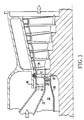
- Figure 2 shows an enlarged view of a portion of the turbine section in the vicinity of the first row vanes 10.
- the invention applies preferably to providing cooling the first row of shrouds, but is applicable to the other rows as well.
- each vane At the radially outboard end of each vane is an outer shroud 11 and at the inboard end is an inner shroud 12.
- Each inner shroud has two approximately axially oriented edges 50 and front and rear circumferentially oriented edges.
- a plurality of vanes 10 are arrayed circumferentially around the annular flow section of the turbine.
- the inner and outer shroud of each vane nearly abut those of the adjacent vane so that, when combined over the entire row, the shrouds form a short axial section of the gas path annulus.
- a housing 20 encases the rotating shaft in the vicinity of the first row vanes. Support rails 16 emanating radially inward from each inner shroud support the vane against this housing.
- High pressure air from the discharge of the compressor flows within the chamber 32 prior to its introduction into the combustion system.
- This high pressure air flows freely into a shroud cavity 24 formed between the inner surface of inner shrouds 12 and the shaft housing 20.
- Rotating blades 28 are affixed to a rotating disc 30 adjacent to the vanes.
- a gap 46 is formed between the down stream edge of the shroud 12 and the face of the adjacent disc 30.
- the support rails 16 provide a radial barrier to leakage of the high pressure air downstream by preventing it from flowing through the shroud cavity 24 and into the hot gas flow through the gap 46.
- Holes 18 are provided in the support rail 16, one hole for each inner shroud.
- the holes extend from the front to the rear face of the rail and are equally spaced circumferentially around the rail.
- a containment cover 14 affixed to the inner surface of the inner shroud allows high pressure air to flow through these holes in the support rail and into the vane airfoil through an opening 15 in the inner shroud.
- the containment cover extends axially from the rear face of the support rail to near the rear circumferentially oriented edge of the shroud and circumferentially it approximately spans the two edges forming the gaps, as shown in Figure 3.
- a means is provided for distributing high pressure air to the gap downstream of the support rail by providing a plurality of holes 36 extending from the slots 38 to the inner surface of the inner shroud encompassed by the containment cover 14 as shown in Figure 4. These holes allow the containment cover to act as a manifold so that the holes 18 in the support rail 16 can supply high pressure air to the slots containing the seal 34.
- a means for regulating and distributing the leakage through the seal by providing intermittent reliefs 42 in the cylindrical portions 40 of the seal 34 downstream of the radial barrier, as shown in Figure 5, the size and quantity of which determine the amount of leakage.
- the amount of leakage flow provided in this manner can also be controlled by varying the size of the holes 18 in the support rail 16. This leakage of high pressure air past the seals and through the circumferential gap between inner shrouds provides a film of air which flows over the outer surface of the inner shroud, thereby cooling it.
Landscapes
- Engineering & Computer Science (AREA)
- Mechanical Engineering (AREA)
- General Engineering & Computer Science (AREA)
- Turbine Rotor Nozzle Sealing (AREA)
Claims (2)
- Eine Gasturbine eines Typs mit einem Turbinenzylinder (48), der abwechselnd Reihen stationärer Leitschaufeln (10) und umlaufender Laufschaufeln (28) enthält, die in einem ringförmigen Strömungsweg angeordnet sind, wobei jede dieser Leitschaufeln (10) ein in Radialrichtung innen liegendes Ende mit einem Innendeckbandteil (12) an jedem dieser in Radialrichtung innen liegenden Enden aufweist, wobei jedes dieser Innendeckbänder (12) erste und zweite Kanten (50) an ihren umfangsmäßigen Enden aufweist, diese Kanten (50) jedes aneinanderstoßenden Paares Innendeckbänder einen in Umfangsrichtung liegenden Spalt (44) bilden; mit einer radialen Sperre (16), die sich umfangsmäßig um dieses Deckband erstreckt und von diesem Deckband aus nach innen vorsteht, um auf diese Weise einen Deckbandhohlraum (24) zu bilden, und wobei diese radiale Sperre (16) den Strom der zu diesem Deckbandhohlraum (24) geleiteten Hochdruckluft einschränkt, und jeweils ein hantelförmiger Dichtstreifen (34) zwischen aneinanderliegenden Deckbändern angeordnet ist, deren jeder zwei zylindrische Längskanten mit entlang diesen Längskanten ausgebildeten Dichtflächen aufweist, die in die in diesen aneinander anliegenden Innendeckbändern (12) ausgebildeten Aussparungen (38) eingesetzt sind, so daß dieser in Umfangsrichtung verlaufender Spalt (44) umspannt wird; dadurch gekennzeichnet, daß eine Vielzahl intermittierender Vorsprünge (42) in jeder dieser zylindrischen Kanten ausgebildet sind, wobei Größe und Anzahl derselben in Abhängigkeit vom gewünschten Leckagestrom gewählt werden, daß Löcher (36) in jedem dieser Innendeckbänder (12) vorgesehen sind, die sich von der Innenfläche des Deckbands zu diesem Schlitz (38) in einer dieser Kanten (50) und von dieser Innenfläche des Deckbands (12) zu diesem Schlitz in der anderen dieser Kanten (50) erstreckt; daß Löcher (18) in dieser radialen Sperre (16) sich von dieser vorderen zu dieser hinteren Seite dieser Sperre (16) erstrecken; und daß jedes dieser Innendeckbänder (12) eine Verteilerleitung (14) hat, die zur Verbindung zwischen diesen Löchern (18) in dieser radialen Sperre (16) und dieser Löchern (36) in dem jeweiligen Innendeckband (12) dient.
- Eine Gasturbine gemäß Anspruch 1, dadurch gekennzeichnet, daß jeder dieser Dichtstreifen (34) einen hantelförmigen Querschnitt aufweist und zylinderförmige Teile (40) hat, wobei sich jeder dieser zylinderförmigen Teile (40) entlang der Länge des jeweiligen Dichtstreifens (34) erstreckt und der Durchmesser dieser zylindrischen Teile (40) ungefähr gleich ist der Breite dieser Schlitze (38), und auf diese Weise diese Dichtflächen ausgebildet sind.
Applications Claiming Priority (2)
| Application Number | Priority Date | Filing Date | Title |
|---|---|---|---|
| US238942 | 1988-08-31 | ||
| US07/238,942 US4902198A (en) | 1988-08-31 | 1988-08-31 | Apparatus for film cooling of turbine van shrouds |
Publications (2)
| Publication Number | Publication Date |
|---|---|
| EP0357984A1 EP0357984A1 (de) | 1990-03-14 |
| EP0357984B1 true EP0357984B1 (de) | 1993-05-05 |
Family
ID=22899953
Family Applications (1)
| Application Number | Title | Priority Date | Filing Date |
|---|---|---|---|
| EP89114666A Expired - Lifetime EP0357984B1 (de) | 1988-08-31 | 1989-08-08 | Gasturbine mit einem gekühlten Leitschaufeldeckring |
Country Status (7)
| Country | Link |
|---|---|
| US (1) | US4902198A (de) |
| EP (1) | EP0357984B1 (de) |
| JP (1) | JP2835382B2 (de) |
| AR (1) | AR240712A1 (de) |
| CA (1) | CA1309597C (de) |
| DE (1) | DE68906334T2 (de) |
| MX (1) | MX164477B (de) |
Cited By (5)
| Publication number | Priority date | Publication date | Assignee | Title |
|---|---|---|---|---|
| GB2280935A (en) * | 1993-06-12 | 1995-02-15 | Rolls Royce Plc | Cooled sealing strip for nozzle guide vane segments |
| EP1013884A3 (de) * | 1998-12-24 | 2003-11-05 | ALSTOM (Switzerland) Ltd | Turbinenschaufel mit aktiv gekültem Deckbandelememt |
| US6705832B2 (en) | 2000-03-02 | 2004-03-16 | Siemens Aktiengesellschaft | Turbine |
| DE19940556B4 (de) * | 1999-08-26 | 2012-02-02 | Alstom | Vorrichtung zum Kühlen von Leit- oder Laufschaufeln in einer Gasturbine |
| US10156150B2 (en) | 2013-03-14 | 2018-12-18 | United Technologies Corporation | Gas turbine engine stator vane platform cooling |
Families Citing this family (60)
| Publication number | Priority date | Publication date | Assignee | Title |
|---|---|---|---|---|
| US5098257A (en) * | 1990-09-10 | 1992-03-24 | Westinghouse Electric Corp. | Apparatus and method for minimizing differential thermal expansion of gas turbine vane structures |
| US5158430A (en) * | 1990-09-12 | 1992-10-27 | United Technologies Corporation | Segmented stator vane seal |
| US5249920A (en) * | 1992-07-09 | 1993-10-05 | General Electric Company | Turbine nozzle seal arrangement |
| US5252026A (en) * | 1993-01-12 | 1993-10-12 | General Electric Company | Gas turbine engine nozzle |
| ES2144147T3 (es) * | 1994-11-10 | 2000-06-01 | Siemens Westinghouse Power | Alabe de turbina de gas con mortaja interna refrigerada. |
| US5531457A (en) * | 1994-12-07 | 1996-07-02 | Pratt & Whitney Canada, Inc. | Gas turbine engine feather seal arrangement |
| US5624227A (en) * | 1995-11-07 | 1997-04-29 | General Electric Co. | Seal for gas turbines |
| DE59710924D1 (de) * | 1997-09-15 | 2003-12-04 | Alstom Switzerland Ltd | Kühlvorrichtung für Gasturbinenkomponenten |
| DE19848103A1 (de) * | 1998-10-19 | 2000-04-20 | Asea Brown Boveri | Dichtungsanordnung |
| EP1008723B1 (de) | 1998-12-10 | 2004-02-18 | ALSTOM (Switzerland) Ltd | Plattformkühlung in Turbomaschinen |
| US6210111B1 (en) * | 1998-12-21 | 2001-04-03 | United Technologies Corporation | Turbine blade with platform cooling |
| US6254333B1 (en) * | 1999-08-02 | 2001-07-03 | United Technologies Corporation | Method for forming a cooling passage and for cooling a turbine section of a rotary machine |
| DE19963371A1 (de) * | 1999-12-28 | 2001-07-12 | Alstom Power Schweiz Ag Baden | Gekühltes Hitzeschild |
| FR2810365B1 (fr) * | 2000-06-15 | 2002-10-11 | Snecma Moteurs | Systeme de ventilation d'une paire de plates-formes d'aubes juxtaposees |
| JP2002201913A (ja) * | 2001-01-09 | 2002-07-19 | Mitsubishi Heavy Ind Ltd | ガスタービンの分割壁およびシュラウド |
| RU2302534C2 (ru) * | 2001-12-11 | 2007-07-10 | Альстом (Свитзерлэнд) Лтд. | Газотурбинное устройство |
| EP1331361B1 (de) | 2002-01-17 | 2010-05-12 | Siemens Aktiengesellschaft | Gegossene Turbinenleitschaufel mit Hakensockel |
| FR2835563B1 (fr) * | 2002-02-07 | 2004-04-02 | Snecma Moteurs | Agencement d'accrochage de secteurs en arc de cercle de distributeur porteur d'aubes |
| DE10209295B4 (de) | 2002-03-01 | 2010-12-09 | Alstom Technology Ltd. | Spaltdichtung bei einer Gasturbine |
| US6883807B2 (en) | 2002-09-13 | 2005-04-26 | Seimens Westinghouse Power Corporation | Multidirectional turbine shim seal |
| US6733234B2 (en) | 2002-09-13 | 2004-05-11 | Siemens Westinghouse Power Corporation | Biased wear resistant turbine seal assembly |
| WO2004074640A1 (de) * | 2003-02-19 | 2004-09-02 | Alstom Technology Ltd | Dichtungsanordnung, insbesondere für die schaufelsegmente von gasturbinen |
| GB0328952D0 (en) * | 2003-12-12 | 2004-01-14 | Rolls Royce Plc | Nozzle guide vanes |
| US7524163B2 (en) * | 2003-12-12 | 2009-04-28 | Rolls-Royce Plc | Nozzle guide vanes |
| JP4495481B2 (ja) * | 2004-02-18 | 2010-07-07 | イーグル・エンジニアリング・エアロスペース株式会社 | シール装置 |
| US7140835B2 (en) * | 2004-10-01 | 2006-11-28 | General Electric Company | Corner cooled turbine nozzle |
| US7217081B2 (en) * | 2004-10-15 | 2007-05-15 | Siemens Power Generation, Inc. | Cooling system for a seal for turbine vane shrouds |
| US7377742B2 (en) * | 2005-10-14 | 2008-05-27 | General Electric Company | Turbine shroud assembly and method for assembling a gas turbine engine |
| JP4690905B2 (ja) * | 2006-02-17 | 2011-06-01 | 三菱重工業株式会社 | シール装置及び該装置を備えたガスタービン |
| EP1892383A1 (de) * | 2006-08-24 | 2008-02-27 | Siemens Aktiengesellschaft | Gasturbinenschaufel mit gekühlter Plattform |
| CH698036B1 (de) * | 2006-09-12 | 2011-11-15 | Parker Hannifin Corp | Dichtungsanordnung. |
| US8308428B2 (en) * | 2007-10-09 | 2012-11-13 | United Technologies Corporation | Seal assembly retention feature and assembly method |
| US8240985B2 (en) * | 2008-04-29 | 2012-08-14 | Pratt & Whitney Canada Corp. | Shroud segment arrangement for gas turbine engines |
| US8206101B2 (en) * | 2008-06-16 | 2012-06-26 | General Electric Company | Windward cooled turbine nozzle |
| ATE537333T1 (de) * | 2009-01-28 | 2011-12-15 | Alstom Technology Ltd | Streifendichtung und verfahren zum entwurf einer streifendichtung |
| US8092159B2 (en) * | 2009-03-31 | 2012-01-10 | General Electric Company | Feeding film cooling holes from seal slots |
| US8371800B2 (en) * | 2010-03-03 | 2013-02-12 | General Electric Company | Cooling gas turbine components with seal slot channels |
| US8814517B2 (en) * | 2010-09-30 | 2014-08-26 | General Electric Company | Apparatus and methods for cooling platform regions of turbine rotor blades |
| US8727710B2 (en) * | 2011-01-24 | 2014-05-20 | United Technologies Corporation | Mateface cooling feather seal assembly |
| US8845272B2 (en) | 2011-02-25 | 2014-09-30 | General Electric Company | Turbine shroud and a method for manufacturing the turbine shroud |
| US8562000B2 (en) * | 2011-05-20 | 2013-10-22 | Siemens Energy, Inc. | Turbine combustion system transition piece side seals |
| US20130177383A1 (en) | 2012-01-05 | 2013-07-11 | General Electric Company | Device and method for sealing a gas path in a turbine |
| US8845285B2 (en) | 2012-01-10 | 2014-09-30 | General Electric Company | Gas turbine stator assembly |
| US8905708B2 (en) | 2012-01-10 | 2014-12-09 | General Electric Company | Turbine assembly and method for controlling a temperature of an assembly |
| US9243510B2 (en) * | 2012-09-10 | 2016-01-26 | General Electric Company | Floating seal |
| US9828872B2 (en) * | 2013-02-07 | 2017-11-28 | General Electric Company | Cooling structure for turbomachine |
| US9581036B2 (en) * | 2013-05-14 | 2017-02-28 | General Electric Company | Seal system including angular features for rotary machine components |
| US9518478B2 (en) | 2013-10-28 | 2016-12-13 | General Electric Company | Microchannel exhaust for cooling and/or purging gas turbine segment gaps |
| US10550706B2 (en) * | 2013-12-12 | 2020-02-04 | United Technolgies Corporation | Wrapped dog bone seal |
| US9416675B2 (en) | 2014-01-27 | 2016-08-16 | General Electric Company | Sealing device for providing a seal in a turbomachine |
| EP2907977A1 (de) * | 2014-02-14 | 2015-08-19 | Siemens Aktiengesellschaft | Heißgasbeaufschlagbares Bauteil für eine Gasturbine sowie Dichtungsanordnung mit einem derartigen Bauteil |
| US9790806B2 (en) | 2014-06-06 | 2017-10-17 | United Technologies Corporation | Case with vane retention feature |
| JP5676040B1 (ja) | 2014-06-30 | 2015-02-25 | 三菱日立パワーシステムズ株式会社 | 静翼、これを備えているガスタービン、静翼の製造方法、及び静翼の改造方法 |
| US10099290B2 (en) | 2014-12-18 | 2018-10-16 | General Electric Company | Hybrid additive manufacturing methods using hybrid additively manufactured features for hybrid components |
| US9587502B2 (en) * | 2015-03-06 | 2017-03-07 | United Technologies Corporation | Sliding compliant seal |
| US10927692B2 (en) * | 2018-08-06 | 2021-02-23 | General Electric Company | Turbomachinery sealing apparatus and method |
| US10890079B2 (en) * | 2018-12-04 | 2021-01-12 | Raytheon Technologies Corporation | Gas turbine engine arc segments with arced walls |
| US20230417326A1 (en) * | 2020-10-22 | 2023-12-28 | Lam Reseach Corporation | Multi-layer and multi-ringed seals for preventing permeation and leak-by of fluid |
| FR3132928B1 (fr) * | 2022-02-21 | 2024-02-16 | Safran Ceram | Assemblage pour une turbomachine d’aeronef |
| CN117490968B (zh) * | 2023-12-22 | 2024-03-08 | 中国空气动力研究与发展中心低速空气动力研究所 | 一种喷流模拟器整流装置及喷口设计方法 |
Family Cites Families (17)
| Publication number | Priority date | Publication date | Assignee | Title |
|---|---|---|---|---|
| GB753224A (en) * | 1953-04-13 | 1956-07-18 | Rolls Royce | Improvements in or relating to blading for turbines or compressors |
| GB761380A (en) * | 1953-11-26 | 1956-11-14 | Power Jets Res & Dev Ltd | Blade mounting for compressors, turbines and like fluid flow machines |
| GB938189A (en) * | 1960-10-29 | 1963-10-02 | Ruston & Hornsby Ltd | Improvements in the construction of turbine and compressor blade elements |
| US3519366A (en) * | 1968-05-22 | 1970-07-07 | Westinghouse Electric Corp | Turbine diaphragm seal structure |
| US3552753A (en) * | 1968-06-26 | 1971-01-05 | Westinghouse Electric Corp | High efficiency static seal assembly |
| US3542483A (en) * | 1968-07-17 | 1970-11-24 | Westinghouse Electric Corp | Turbine stator structure |
| US3752598A (en) * | 1971-11-17 | 1973-08-14 | United Aircraft Corp | Segmented duct seal |
| US3947145A (en) * | 1974-10-07 | 1976-03-30 | Westinghouse Electric Corporation | Gas turbine stationary shroud seals |
| US3938906A (en) * | 1974-10-07 | 1976-02-17 | Westinghouse Electric Corporation | Slidable stator seal |
| US3975114A (en) * | 1975-09-23 | 1976-08-17 | Westinghouse Electric Corporation | Seal arrangement for turbine diaphragms and the like |
| US4353679A (en) * | 1976-07-29 | 1982-10-12 | General Electric Company | Fluid-cooled element |
| GB1580884A (en) * | 1977-08-03 | 1980-12-10 | Rolls Royce | Sealing means |
| US4650394A (en) * | 1984-11-13 | 1987-03-17 | United Technologies Corporation | Coolable seal assembly for a gas turbine engine |
| US4688988A (en) * | 1984-12-17 | 1987-08-25 | United Technologies Corporation | Coolable stator assembly for a gas turbine engine |
| US4720236A (en) * | 1984-12-21 | 1988-01-19 | United Technologies Corporation | Coolable stator assembly for a gas turbine engine |
| GB2195403A (en) * | 1986-09-17 | 1988-04-07 | Rolls Royce Plc | Improvements in or relating to sealing and cooling means |
| US4767260A (en) * | 1986-11-07 | 1988-08-30 | United Technologies Corporation | Stator vane platform cooling means |
-
1988
- 1988-08-31 US US07/238,942 patent/US4902198A/en not_active Expired - Fee Related
-
1989
- 1989-08-08 DE DE8989114666T patent/DE68906334T2/de not_active Expired - Fee Related
- 1989-08-08 EP EP89114666A patent/EP0357984B1/de not_active Expired - Lifetime
- 1989-08-11 CA CA000608158A patent/CA1309597C/en not_active Expired - Lifetime
- 1989-08-30 MX MX17355A patent/MX164477B/es unknown
- 1989-08-31 JP JP1227281A patent/JP2835382B2/ja not_active Expired - Fee Related
- 1989-08-31 AR AR31481489A patent/AR240712A1/es active
Cited By (5)
| Publication number | Priority date | Publication date | Assignee | Title |
|---|---|---|---|---|
| GB2280935A (en) * | 1993-06-12 | 1995-02-15 | Rolls Royce Plc | Cooled sealing strip for nozzle guide vane segments |
| EP1013884A3 (de) * | 1998-12-24 | 2003-11-05 | ALSTOM (Switzerland) Ltd | Turbinenschaufel mit aktiv gekültem Deckbandelememt |
| DE19940556B4 (de) * | 1999-08-26 | 2012-02-02 | Alstom | Vorrichtung zum Kühlen von Leit- oder Laufschaufeln in einer Gasturbine |
| US6705832B2 (en) | 2000-03-02 | 2004-03-16 | Siemens Aktiengesellschaft | Turbine |
| US10156150B2 (en) | 2013-03-14 | 2018-12-18 | United Technologies Corporation | Gas turbine engine stator vane platform cooling |
Also Published As
| Publication number | Publication date |
|---|---|
| DE68906334T2 (de) | 1993-08-26 |
| AR240712A1 (es) | 1990-09-28 |
| US4902198A (en) | 1990-02-20 |
| DE68906334D1 (de) | 1993-06-09 |
| CA1309597C (en) | 1992-11-03 |
| EP0357984A1 (de) | 1990-03-14 |
| JPH02104902A (ja) | 1990-04-17 |
| MX164477B (es) | 1992-08-19 |
| JP2835382B2 (ja) | 1998-12-14 |
Similar Documents
| Publication | Publication Date | Title |
|---|---|---|
| EP0357984B1 (de) | Gasturbine mit einem gekühlten Leitschaufeldeckring | |
| EP0775805B1 (de) | Statorring | |
| EP0578460B1 (de) | Gasturbine | |
| EP0752052B1 (de) | Turbinenschaufel mit dichtungselement und einem integralen hitzeschild | |
| EP0753100B1 (de) | Turbinengehäusesegment mit haarnadelförmigen kühlkanälen | |
| EP0381955A1 (de) | Gasturbine mit luftgekühlten Schaufeln | |
| US5374161A (en) | Blade outer air seal cooling enhanced with inter-segment film slot | |
| EP0725888B1 (de) | Montage- und abdichtungssystem für segmente eines turbinenmantelringes | |
| EP0974733B1 (de) | Turbinenleitgitter mit einem Kühlluftleitsystem | |
| EP2055898B1 (de) | Gasturbinentriebwerk mit in Umfangsrichtung angeordneten Schaufeln mit Plattformkühlung | |
| EP0916811B1 (de) | Gerippte Turbinenschaufelspitze | |
| US5215435A (en) | Angled cooling air bypass slots in honeycomb seals | |
| US4688988A (en) | Coolable stator assembly for a gas turbine engine | |
| US4648799A (en) | Cooled combustion turbine blade with retrofit blade seal | |
| US3425665A (en) | Gas turbine rotor blade shroud | |
| EP1088963A2 (de) | Methode und Einrichtung zum Spülen von Hohlräumen in Turbinenrädern | |
| CA2048800C (en) | Windage shield | |
| EP0808413A1 (de) | Konfiguration der gebogenen abschnitte von serpentinenförmigen kühlkanälen in turbinen | |
| EP0682741B1 (de) | Äussere luftabdichtung für ein gasturbinentriebwerk | |
| EP0728258B1 (de) | Deckbandsegment einer turbine | |
| EP1306524B1 (de) | Konfiguration der Kühlbohrungen von Turbinenmantelsegmenten | |
| US6571470B1 (en) | Method of retrofitting seals in a gas turbine | |
| EP0144842B1 (de) | Stufenweise Luftzufuhr zur Kühlung einer Gasturbine |
Legal Events
| Date | Code | Title | Description |
|---|---|---|---|
| PUAI | Public reference made under article 153(3) epc to a published international application that has entered the european phase |
Free format text: ORIGINAL CODE: 0009012 |
|
| AK | Designated contracting states |
Kind code of ref document: A1 Designated state(s): CH DE FR GB IT LI NL SE |
|
| 17P | Request for examination filed |
Effective date: 19900914 |
|
| 17Q | First examination report despatched |
Effective date: 19910704 |
|
| GRAA | (expected) grant |
Free format text: ORIGINAL CODE: 0009210 |
|
| AK | Designated contracting states |
Kind code of ref document: B1 Designated state(s): CH DE FR GB IT LI NL SE |
|
| PG25 | Lapsed in a contracting state [announced via postgrant information from national office to epo] |
Ref country code: SE Effective date: 19930505 Ref country code: LI Effective date: 19930505 Ref country code: CH Effective date: 19930505 |
|
| ITF | It: translation for a ep patent filed | ||
| REF | Corresponds to: |
Ref document number: 68906334 Country of ref document: DE Date of ref document: 19930609 |
|
| ET | Fr: translation filed | ||
| REG | Reference to a national code |
Ref country code: CH Ref legal event code: PL |
|
| PLBE | No opposition filed within time limit |
Free format text: ORIGINAL CODE: 0009261 |
|
| STAA | Information on the status of an ep patent application or granted ep patent |
Free format text: STATUS: NO OPPOSITION FILED WITHIN TIME LIMIT |
|
| 26N | No opposition filed | ||
| PGFP | Annual fee paid to national office [announced via postgrant information from national office to epo] |
Ref country code: NL Payment date: 19940831 Year of fee payment: 6 |
|
| PG25 | Lapsed in a contracting state [announced via postgrant information from national office to epo] |
Ref country code: NL Effective date: 19960301 |
|
| NLV4 | Nl: lapsed or anulled due to non-payment of the annual fee |
Effective date: 19960301 |
|
| PGFP | Annual fee paid to national office [announced via postgrant information from national office to epo] |
Ref country code: GB Payment date: 19960710 Year of fee payment: 8 |
|
| PGFP | Annual fee paid to national office [announced via postgrant information from national office to epo] |
Ref country code: FR Payment date: 19960816 Year of fee payment: 8 |
|
| PGFP | Annual fee paid to national office [announced via postgrant information from national office to epo] |
Ref country code: DE Payment date: 19960828 Year of fee payment: 8 |
|
| PG25 | Lapsed in a contracting state [announced via postgrant information from national office to epo] |
Ref country code: GB Free format text: LAPSE BECAUSE OF NON-PAYMENT OF DUE FEES Effective date: 19970808 |
|
| GBPC | Gb: european patent ceased through non-payment of renewal fee |
Effective date: 19970808 |
|
| PG25 | Lapsed in a contracting state [announced via postgrant information from national office to epo] |
Ref country code: FR Free format text: LAPSE BECAUSE OF NON-PAYMENT OF DUE FEES Effective date: 19980430 |
|
| PG25 | Lapsed in a contracting state [announced via postgrant information from national office to epo] |
Ref country code: DE Free format text: LAPSE BECAUSE OF NON-PAYMENT OF DUE FEES Effective date: 19980501 |
|
| REG | Reference to a national code |
Ref country code: FR Ref legal event code: ST |
|
| PG25 | Lapsed in a contracting state [announced via postgrant information from national office to epo] |
Ref country code: IT Free format text: LAPSE BECAUSE OF NON-PAYMENT OF DUE FEES Effective date: 20050808 |