EP0358041A1 - Procédé pour chauffer un bâtiment et installation de chauffage - Google Patents
Procédé pour chauffer un bâtiment et installation de chauffage Download PDFInfo
- Publication number
- EP0358041A1 EP0358041A1 EP89115502A EP89115502A EP0358041A1 EP 0358041 A1 EP0358041 A1 EP 0358041A1 EP 89115502 A EP89115502 A EP 89115502A EP 89115502 A EP89115502 A EP 89115502A EP 0358041 A1 EP0358041 A1 EP 0358041A1
- Authority
- EP
- European Patent Office
- Prior art keywords
- tank
- water
- circulation
- solar
- temperature
- Prior art date
- Legal status (The legal status is an assumption and is not a legal conclusion. Google has not performed a legal analysis and makes no representation as to the accuracy of the status listed.)
- Granted
Links
Images


Classifications
-
- F—MECHANICAL ENGINEERING; LIGHTING; HEATING; WEAPONS; BLASTING
- F24—HEATING; RANGES; VENTILATING
- F24D—DOMESTIC- OR SPACE-HEATING SYSTEMS, e.g. CENTRAL HEATING SYSTEMS; DOMESTIC HOT-WATER SUPPLY SYSTEMS; ELEMENTS OR COMPONENTS THEREFOR
- F24D3/00—Hot-water central heating systems
- F24D3/10—Feed-line arrangements, e.g. providing for heat-accumulator tanks, expansion tanks ; Hydraulic components of a central heating system
- F24D3/1091—Mixing cylinders
-
- F—MECHANICAL ENGINEERING; LIGHTING; HEATING; WEAPONS; BLASTING
- F24—HEATING; RANGES; VENTILATING
- F24D—DOMESTIC- OR SPACE-HEATING SYSTEMS, e.g. CENTRAL HEATING SYSTEMS; DOMESTIC HOT-WATER SUPPLY SYSTEMS; ELEMENTS OR COMPONENTS THEREFOR
- F24D11/00—Central heating systems using heat accumulated in storage masses
- F24D11/002—Central heating systems using heat accumulated in storage masses water heating system
- F24D11/003—Central heating systems using heat accumulated in storage masses water heating system combined with solar energy
-
- F—MECHANICAL ENGINEERING; LIGHTING; HEATING; WEAPONS; BLASTING
- F24—HEATING; RANGES; VENTILATING
- F24D—DOMESTIC- OR SPACE-HEATING SYSTEMS, e.g. CENTRAL HEATING SYSTEMS; DOMESTIC HOT-WATER SUPPLY SYSTEMS; ELEMENTS OR COMPONENTS THEREFOR
- F24D3/00—Hot-water central heating systems
- F24D3/10—Feed-line arrangements, e.g. providing for heat-accumulator tanks, expansion tanks ; Hydraulic components of a central heating system
- F24D3/1058—Feed-line arrangements, e.g. providing for heat-accumulator tanks, expansion tanks ; Hydraulic components of a central heating system disposition of pipes and pipe connections
-
- Y—GENERAL TAGGING OF NEW TECHNOLOGICAL DEVELOPMENTS; GENERAL TAGGING OF CROSS-SECTIONAL TECHNOLOGIES SPANNING OVER SEVERAL SECTIONS OF THE IPC; TECHNICAL SUBJECTS COVERED BY FORMER USPC CROSS-REFERENCE ART COLLECTIONS [XRACs] AND DIGESTS
- Y02—TECHNOLOGIES OR APPLICATIONS FOR MITIGATION OR ADAPTATION AGAINST CLIMATE CHANGE
- Y02B—CLIMATE CHANGE MITIGATION TECHNOLOGIES RELATED TO BUILDINGS, e.g. HOUSING, HOUSE APPLIANCES OR RELATED END-USER APPLICATIONS
- Y02B10/00—Integration of renewable energy sources in buildings
- Y02B10/20—Solar thermal
Definitions
- the invention relates to a method for heating a building with a heating circuit having at least one radiator, through which water circulates, driven by a pump.
- the invention has for its object to provide a method for heating a building with which the temperature of the water flowing through the radiator can be adjusted very sensitively.
- the water when heat is required, the water is withdrawn from the heating circuit and passed into a tank with water at a higher temperature, from which the water withdrawn from the heating circuit is replaced by warmer water.
- the heating circuit is uncoupled from the tank again and water flows through the heating circuit at a constant, warmer temperature. In this way, the temperature can be metered very sensitively and it can be ensured with simple effort that the temperature in the heating circuit does not exceed the value mentioned, for example 25 ° C.
- the water in the heating circuit is passed through a circulation tank arranged approximately at the level of the tank, from the lower area of which the water is drawn off when heat is required and in the upper area the warmer water is introduced.
- This circulation tank serves to ensure that the heating circuit has a certain thermal inertia, so that water does not have to be replaced too often.
- the circulation tank should be of such a small size that the thermal inertia is not too great so that the temperature does not overshoot when the temperature is adjusted.
- the amount of water in the circulation tank should be small compared to the amount of water in the tank.
- the temperature of the heating system is independent of how high the temperature of the water in the tank is.
- the method can be used in particular with solar-powered heating systems in which it is not possible to predict the temperature of the water in the tank.
- the water is fed into the circulation tank of the heating circuit at a point below the line leading to the radiator.
- the warmer water from the tank is already mixed with the colder water in the circulation tank.
- the temperature can be measured at a point which is between the point of introduction of the warmer water from the tank and the further pipeline.
- the tank is flowed through in a shunt in a further development of the invention.
- This also means that the temperature is particularly careful when the warmer water is mixed in, if it has a significantly higher temperature.
- the warmer water is removed from the tank only when necessary and is replaced by colder water, and since the type of temperature control proposed by the invention is independent of the temperature of the water in the tank, it can be provided according to the invention for heating the water in the tank that the water in the tank is heated by an additional heater of low power. This heating can then run practically continuously, if necessary until a maximum temperature in the tank is reached.
- a small night power heater or a small gas heater can be used, for example, as an additional heater of low power.
- the water is conducted into the solar circuit through a circulation tank arranged approximately at the level of the tank.
- This circulation tank has a similar function as the circulation tank in the heating circuit. This is because it can be used to keep the thermal inertia in the solar circuit at certain values.
- the thermal inertia of the solar circuit should be relatively low, but at least reach a certain value.
- the invention proposes in a further development that the water is only drawn off from the circulation tank into the tank and is replaced by cold water from the lower region of the tank when the water temperature in the circulation tank is higher than an average temperature of the tank. Before this temperature is reached, the solar circuit is flowed through in a closed circuit, so that the water itself continually warmed up.
- the warm water is only drawn off when a higher temperature is reached. In this case, as can be provided in a further development, it is removed from the upper area of the circulation container and directed into the upper area of the tank. The colder water on the underside is then removed from the tank and likewise introduced into the lower region of the circulation tank. It can also be provided here that the tank is flowed through in the secondary flow.
- the water circulation in the solar circuit is started by a pump when the temperature at the solar collectors is higher than a predetermined fixed temperature of, for example, 15 ° C.
- a predetermined fixed temperature for example, 15 ° C.
- the heating circuit and the solar circuit are depressurized. This makes installation easier. In the solar circuit in particular, this has the advantage that it flows empty when the pump is switched off.
- the water is taken from the circulation tank of the solar circuit at a point below the mouth of the line coming from the solar collectors, and that the temperature is measured between these two points.
- the invention is also based on the object to provide a heating system which is easy to carry out Temperature control in buildings with the help of low temperature radiators can be used.
- the invention proposes a heating system with at least one radiator, water-flowed heating circuit and a temperature control in which a heating tank is contained in the heating circuit, which is approximately at the same height as a water tank and with this in the upper and lower area is connected via a line.
- the control device for regulating the room temperature can then establish a connection between the circulation tank and the tank, this connection being established whenever a heat requirement is signaled.
- connection can be established through one or both of these lines, for example, by an electrically operated servo valve.
- a pump is arranged in one of the two lines and is controlled by the temperature control device. This pump blocks the connection when it is not in operation. It only needs to be arranged in one of the lines, since if the connection is interrupted by one of the lines, the other line is not flowed through.
- the pump is arranged in the lower connecting line between the heating circuit and the tank and works in the direction from the heating circuit to the tank. It pumps cold water from the heating circuit in the tank. The same amount of warm water then flows through the upper connecting pipe in the opposite direction.
- the upper connecting line between the tank and the circulation tank opens into the latter below the line of the heating circuit leading to the radiators. This leads to the fact that the outflowing water in the circulation tank initially with the existing one Water mixes before it gets into the pipe to the radiators.
- the temperature sensor which is to register the temperature in the circulation tank, is advantageously arranged in the height between the two lines on or in the circulation tank.
- the heating circuit and the tank operate without pressure
- the circulation tank is connected to the tank via a vent line, the tank preferably being further vented.
- a water surface forms in the tank and in the circulation tank.
- the heating system has a solar circuit which contains at least one solar collector, a circulating pump and a circulation tank arranged approximately at the level of the tank. This is connected to the tank in its upper and lower area via a line. A connection through the lines can be established by controlling the solar system. This can be done using servo valves, for example. It is again particularly favorable if a pump which can be switched on by the control of the solar system is arranged in one of the two lines. In the case of the circulation tank for the solar system, this is preferably a pump in the upper line, which works in the direction from the solar circuit to the tank.
- the control of the solar system is set in such a way that it starts the circulation pump when the temperature at the solar collectors is higher than a predetermined temperature of, for example, 15 ° C.
- a controller activates the connection between the circulation tank and the tank when the temperature in the circulation tank is higher than a temperature of the tank in its central region. In this way, a good temperature stratification can be produced in the tank, so that there is hot water at the top and cold water at the bottom without mixing.
- the connecting line between the tank and the circulation tank of the solar circuit opens into the circulation tank below the line coming from the solar collectors.
- the temperature sensor can advantageously be arranged on or in the circulation tank between these two upper lines.
- the amount of water in the solar circuit is small compared to the amount of water in the tank.
- the ratio of the content of the circulation tank to the tank content can be approximately 1%.
- the circulation tank for the heating circuit and / or the circulation tank for the solar circuit can advantageously have the same height as the tank. If they have a smaller height, which is also possible, their tops should be approximately flush with one another, which is particularly important in depressurized systems, since the same water level is established in the tank and the circulation tanks.
- the circulation containers can advantageously have a cylindrical shape, the diameter of which is in the range from approximately ten to approximately 50 cm.
- an externally operated heating device of low power can be provided as an additive for heating the water in the tank, for example a gas heater or an electric heating device operated with night-time electricity.
- the tank has a heat exchanger for industrial water.
- the tank is filled according to the invention only to such an extent that the water from the heating circuit and the solar circuit still has space in it.
- the invention also proposes the use of such a heating system for heating a building using the method mentioned.
- the heating circuit shown schematically in FIG. 1 there is a large tank 11, for example to be accommodated in the basement of a building, which is used to hold water. This water serves as a medium for storing heat.
- Fig. 1 to the left of the tank 11 the heating circuit is shown, while to the right of the tank the solar circuit and an additional heater are shown.
- the heating circuit 12 initially contains a system of lines which bring water as heating medium to one or more radiators 13, from where the water flows back through a return line 14.
- the circulating water is driven by a pump 15.
- the heating circuit 12 contains a circulation tank 16 which is arranged at approximately the same height next to the tank 11.
- the water contained in the circulation tank 16 is removed via a line 17 in the upper region and is drawn in by the pump 15 a distributor 17 pumped. From the distributor 17, the water then reaches the individual radiators, only a single radiator 13 being shown in the simplified illustration in FIG. 1. From the radiators 13, the water returns via the return line 14 to the circulation tank.
- the circulation tank is only flowed through by water; it does not itself contain any heating device.
- a room temperature control which has a control device 18, is provided for the heating circuit 12.
- the control device 18 measures the temperature of the room to be heated with the aid of a first temperature sensor 19, and the temperature of the water in the upper region of the circulation tank 16 with a second temperature sensor 20 Has to heat water in the heating circuit 12 and when it should stop this heating.
- the circulation tank is in the upper area with a first connecting line 21 for warm water and in its lower Area connected to a second connection line 22, namely for cold water.
- a pump 23 is arranged in the lower connecting line for cold water and, when it is not in operation, blocks the connecting line 22.
- the pump 23 is switched on and off by the control device 18 of the heating system. As soon as it determines that an increase in the temperature of the water in the heating circuit 12 is required, it starts the pump 23. As a result, colder water is drawn off from the lower region of the circulation tank 16 and pumped into the tank 11. The same amount of water flows from the tank 11 through the connecting line 21 back into the circulation tank 16.
- the water in the tank 11 is usually warmer than the water in the heating circuit 12, so that the temperature in the heating circuit 12 is increased by mixing in the warmer Water increased.
- the control device 18 determines on the basis of the information from the temperature sensor 20 that the water in the heating circuit has risen to a temperature of, for example, 25 or 26 ° C., it switches the pump 23 off again. Now the somewhat warmer water flows in the heating circuit 12 and leads to an increase in the temperature of the building to be heated.
- FIG. 1 is not drawn to scale. Nevertheless, it can be seen that the volume of the circulation container 16 is significantly lower than that of the tank 11.
- the tank 11 should be as large as possible in order to be able to store as large a quantity of heat as possible.
- the circulation tank 16, on the other hand, should be small so that the thermal inertia of the heating circuit does not become too large. On the other hand, it should also not be too small so that warmer water is not mixed in too often. It is supposed to take on a certain balancing function for the temperature.
- the water in the tank 11 can be heated in two ways.
- an externally operated auxiliary heater is provided, which is always is then put into operation when the water in the upper region of the tank 11 falls below a certain temperature of, for example, 40 ° C.
- the additional heater is connected to the tank via a lower connection heater 25.
- a pump 26 is inserted in this lower connecting line 25.
- the additional heater 24 is also connected to the upper region of the tank 11 via an upper connecting line 27.
- the auxiliary heater 24 and its pump 26 are controlled by a control device 28, which measures the temperature in the upper region of the tank 11 with the aid of a temperature sensor 29.
- the control device 28 switches on the pump 26 and the heating of the additional heater 24, so that water is removed from the lower region of the tank 11, heated in the additional heater 24 and through the connecting line 27 into the upper region of the tank is fed. As soon as the temperature at the temperature sensor 29 reaches 50 ° C., for example, the heating is switched off again.
- This additional heater 24 only needs to deliver a low power, since it can work continuously.
- a solar system with a solar circuit 30 is provided as the actual heating for the water in the tank 11. Similar to the heating circuit, the solar circuit contains a circulation container 31 which is arranged approximately at the same height as the tank 11 and also has approximately the same height.
- the circulation tank 31 is connected to the tank 11 via a lower connecting line 32 and an upper connecting line 33.
- a pump 34 is arranged in the upper connecting line 33 and is constructed in a manner similar to the pump 23 of the connecting line 22.
- the solar circuit contains a circulation pump 35 which takes water from the lower area of the circulation tank 31 and pumps via a riser 36 to the solar collectors 37, which are only shown schematically.
- Vacuum collectors are preferably used as solar collectors, in which the heat is emitted at one, namely the upper end of the collectors.
- the line 36 passes, so that the collectors 37 heat the water present there.
- the temperature of the collectors 37 is determined by a temperature sensor 38.
- the water heated by the solar collectors 37 passes through a vented down pipe 39 into the upper region of the circulation tank 31. There its temperature is measured with a further temperature sensor 40.
- a temperature sensor 41 is also arranged in the central region of the circulation container 31.
- the temperature sensors 40, 41 in the circulation tank 31 and the temperature sensor 38 for the solar collectors 37 are connected to a control device 42 for the solar system.
- This control device 42 uses a repeated temperature sensor 43 to determine the temperature in a middle or lower region of the tank 11.
- the temperature in the upper region of the tank 11 can also be communicated here via the temperature sensor 29.
- the operation of the solar system is as follows.
- the control device 42 determines when the temperature at the solar collectors 37 is higher than a previously set fixed temperature of e.g. B. 15 ° C.
- the pump 35 is started. This pumps the cold water from the circulation tank 31 via the riser 36 to the solar collectors, where it is heated and returns to the circulation tank 31 via the down pipe 39.
- the pump 34 is out of operation at this time.
- the now somewhat warmer water is heated again during the next cycle.
- the water is always warmer until it is warmer than the water in the central region of the tank 11 at a certain point in time.
- control device 42 switches on the pump 34, which pumps the water out of the pumps the upper region of the circulation container 31 into the upper region of the tank, specifically below its water level.
- the warm water removed from the circulation tank 31 is replaced by colder water from the lower region of the tank 11 via the line 32, so that this colder water is now heated by the solar collectors 37.
- the volume of the circulation container 31 is selected such that the heat capacity is small enough on the one hand. On the other hand, the amount should be large enough so that the water in the circulation tank 31 does not reach the temperature in the central region of the tank 11 too quickly.
- Both the heating circuit 12 and the solar circuit 30 are open systems, i. H. there may be air in them in the return line 14 or in the down line 39. In the solar circuit 30, this is represented by the open branch of the line 39. When the circulation pump 35 is switched off, the solar circuit empties.
- the tank 11 contains a ventilation line 45, the circulation tank 31 also having a ventilation line.
- the circulation tank also contains a vent. All vents can lead to an activated carbon filter.
- Fig. 1 indicates that a heat exchanger 46 is present in the tank 11, which is used to provide hot water.
- the tank 11 contains approximately 40 cm3 of water, the heating circuit approximately 2 cm3 and the solar circuit run about the same value.
- the output of the auxiliary heater 24 is 20 kW, for example.
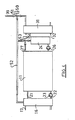
- FIG. 2 also shows in simplified form the circulation tank 16 for the heating circuit 12. It is designed as a cylinder and has a diameter of between approximately 10 and approximately 40 cm, for example.
- the vent line 44 is arranged in its upper end face.
- the water level is indicated by the wavy line 47.
- the line 17 to the circulation pump 15 opens slightly below the water level.
- the connecting line 21 to the tank 11 is arranged below the line 17, the temperature sensor 20 being arranged between the two heights.
- the displacement of the line 21 downwards leads to a mixing of the warm water of the line 21 with the already existing colder water takes place in the circulation tank 16, which still has water flowing through it. As a result, water with a mixed temperature already reaches the pump 15, and the temperature sensor 20 does not measure the temperature of the water flowing out of the line 21 either.
- the second temperature sensor 41 is arranged in the lower to middle region of the circulation container 31.
- both circulation tanks it is important that they align with the tank 11 in the upper area, since a water level is formed in both circulation tanks 31. If shorter circulation tanks 31, 16 are used, they are arranged so that they are at approximately the same height as the tank 11 at the top.
- the circulation tank 31 While in the circulation tank 31 the water leading to the collectors is removed from the lower area, it is also possible to remove the water from the central area or from the central and lower areas simultaneously. In the latter case, the ratio of water from the middle and lower range can be different from 1. This can prevent the temperature of the water pumped to the collectors from dropping too much.
- the line coming from the solar collectors 37, through which the heated water flows, does not reach the circulation tank 31 directly, as in the system of FIG. 1, but to a multi-way valve 51 which can be actuated by an electric drive 50.
- This can be done by the electric drive 50 be actuated that in one way the water coming from the collectors 37, exactly as in the embodiment of FIG. 1, flows into the associated circulation tank 31.
- the valve 51 can also be switched so that the heated water via a line 52 to the circulation tank 31 and the tank 11th run 12 flows. In this way, if there is a sudden need for heat in the heating circuit, the heated water coming from the solar collectors 37 can be fed directly into the heating circuit 12 without taking the detour via the tank 11.
- the output of the additional auxiliary heater 24 is connected to a multi-way valve 53 which can be actuated by an electric drive 54.
- the multi-way valve 53 can be controlled on the one hand so that the output of the additional heating is passed through line 27 into the tank. This would be the same method as in the embodiment according to FIG. 1.
- the valve 53 can also be controlled in such a way that the water heated by the additional heating 24 is fed directly into the circulation tank 16 of the heating circuit 12 via the already mentioned line 52. This possibility can also be used to bypass the tank 11 when there is a sudden need for heat in the circuit 12.
Landscapes
- Engineering & Computer Science (AREA)
- General Engineering & Computer Science (AREA)
- Chemical & Material Sciences (AREA)
- Thermal Sciences (AREA)
- Combustion & Propulsion (AREA)
- Mechanical Engineering (AREA)
- Physics & Mathematics (AREA)
- Sustainable Development (AREA)
- Life Sciences & Earth Sciences (AREA)
- Sustainable Energy (AREA)
- Steam Or Hot-Water Central Heating Systems (AREA)
- Heat-Pump Type And Storage Water Heaters (AREA)
- Buildings Adapted To Withstand Abnormal External Influences (AREA)
- Chemical And Physical Treatments For Wood And The Like (AREA)
- Mirrors, Picture Frames, Photograph Stands, And Related Fastening Devices (AREA)
Priority Applications (1)
| Application Number | Priority Date | Filing Date | Title |
|---|---|---|---|
| AT89115502T ATE91336T1 (de) | 1988-08-27 | 1989-08-23 | Verfahren zum beheizen eines gebaeudes und heizungsanlage. |
Applications Claiming Priority (2)
| Application Number | Priority Date | Filing Date | Title |
|---|---|---|---|
| DE3829097A DE3829097A1 (de) | 1988-08-27 | 1988-08-27 | Verfahren zum beheizen eines gebaeudes und heizungsanlage |
| DE3829097 | 1988-08-27 |
Publications (2)
| Publication Number | Publication Date |
|---|---|
| EP0358041A1 true EP0358041A1 (fr) | 1990-03-14 |
| EP0358041B1 EP0358041B1 (fr) | 1993-07-07 |
Family
ID=6361701
Family Applications (1)
| Application Number | Title | Priority Date | Filing Date |
|---|---|---|---|
| EP89115502A Expired - Lifetime EP0358041B1 (fr) | 1988-08-27 | 1989-08-23 | Procédé pour chauffer un bâtiment et installation de chauffage |
Country Status (3)
| Country | Link |
|---|---|
| EP (1) | EP0358041B1 (fr) |
| AT (1) | ATE91336T1 (fr) |
| DE (2) | DE3829097A1 (fr) |
Cited By (2)
| Publication number | Priority date | Publication date | Assignee | Title |
|---|---|---|---|---|
| FR2740204A1 (fr) * | 1995-10-18 | 1997-04-25 | Guillot Ind Sa | Dispositif de raccordement sur une chaudiere regulee permettant l'alimentation et la regulation de deux circuits de chauffage |
| WO2014125306A1 (fr) * | 2013-02-18 | 2014-08-21 | Ideal Boilers Limited | Appareil chauffant l'eau |
Families Citing this family (2)
| Publication number | Priority date | Publication date | Assignee | Title |
|---|---|---|---|---|
| AT403842B (de) * | 1994-08-03 | 1998-05-25 | Vaillant Gmbh | Heizungsanlage mit zwei brauchwasserspeichern |
| AT402662B (de) * | 1995-04-03 | 1997-07-25 | Vaillant Gmbh | Heizanlage mit einem brennerbeheizten heizanlage mit einem brennerbeheizten primärwärmetauscher primärwärmetauscher |
Citations (3)
| Publication number | Priority date | Publication date | Assignee | Title |
|---|---|---|---|---|
| FR2452675A1 (fr) * | 1979-03-28 | 1980-10-24 | Eidenschenck Roland | Installation polyvalente de chauffage domestique et d'eau sanitaire |
| FR2505459A1 (fr) * | 1981-05-05 | 1982-11-12 | Amblard Francois | Ensemble de raccordement entre un generateur de chaleur principal et un generateur d'appoint ou de remplacement, parcourus par un meme fluide caloporteur |
| FR2566885A1 (fr) * | 1984-07-02 | 1986-01-03 | Moureau Marie Lucienne | Nouveau type de capteur solaire |
Family Cites Families (2)
| Publication number | Priority date | Publication date | Assignee | Title |
|---|---|---|---|---|
| IT1126116B (it) * | 1979-06-04 | 1986-05-14 | Zanussi A Spa Industrie | Impianto di riscaldamento ad energia solare |
| DE3428479A1 (de) * | 1984-08-02 | 1986-02-13 | E. Cacarda GmbH, 8602 Strullendorf | Niedertemperatur-luftheizungsanlage |
-
1988
- 1988-08-27 DE DE3829097A patent/DE3829097A1/de not_active Withdrawn
-
1989
- 1989-08-23 AT AT89115502T patent/ATE91336T1/de not_active IP Right Cessation
- 1989-08-23 DE DE8989115502T patent/DE58904865D1/de not_active Expired - Fee Related
- 1989-08-23 EP EP89115502A patent/EP0358041B1/fr not_active Expired - Lifetime
Patent Citations (3)
| Publication number | Priority date | Publication date | Assignee | Title |
|---|---|---|---|---|
| FR2452675A1 (fr) * | 1979-03-28 | 1980-10-24 | Eidenschenck Roland | Installation polyvalente de chauffage domestique et d'eau sanitaire |
| FR2505459A1 (fr) * | 1981-05-05 | 1982-11-12 | Amblard Francois | Ensemble de raccordement entre un generateur de chaleur principal et un generateur d'appoint ou de remplacement, parcourus par un meme fluide caloporteur |
| FR2566885A1 (fr) * | 1984-07-02 | 1986-01-03 | Moureau Marie Lucienne | Nouveau type de capteur solaire |
Cited By (2)
| Publication number | Priority date | Publication date | Assignee | Title |
|---|---|---|---|---|
| FR2740204A1 (fr) * | 1995-10-18 | 1997-04-25 | Guillot Ind Sa | Dispositif de raccordement sur une chaudiere regulee permettant l'alimentation et la regulation de deux circuits de chauffage |
| WO2014125306A1 (fr) * | 2013-02-18 | 2014-08-21 | Ideal Boilers Limited | Appareil chauffant l'eau |
Also Published As
| Publication number | Publication date |
|---|---|
| DE58904865D1 (de) | 1993-08-12 |
| ATE91336T1 (de) | 1993-07-15 |
| EP0358041B1 (fr) | 1993-07-07 |
| DE3829097A1 (de) | 1990-03-08 |
Similar Documents
| Publication | Publication Date | Title |
|---|---|---|
| DE2619744C2 (de) | Anlage zum Beheizen eines Gebäudes und zur Warmwasserbereitung | |
| DE1604205A1 (de) | Klimaanlage | |
| DE2638354A1 (de) | Zentralheizungsanlage | |
| DE4035115C2 (de) | Anordnung zum aufheizen und zum bereitstellen von warmem oder heissem brauchwasser von trinkwasserqualitaet | |
| DE2411308A1 (de) | Heizungs- und/oder klimaanlage | |
| WO2009095010A2 (fr) | Dispositif de chauffage | |
| AT508481B1 (de) | Verfahren zur erwärmung von brauchwasser | |
| DE2614118C2 (de) | Heiz- oder Kühlanlage | |
| DE4208958A1 (de) | Waermespeicher als pufferspeicher fuer eine raumheizung | |
| EP2492599B1 (fr) | Installation de chauffage dotée d'une combustion de biomasse et d'une pompe à chaleur | |
| EP0358041B1 (fr) | Procédé pour chauffer un bâtiment et installation de chauffage | |
| EP0115014B1 (fr) | Procédé pour l'économie d'énergie à commande de température d'air dans des bâtiments et bâtiment permettant la mise en oeuvre du procédé | |
| DE2804748B1 (de) | Waerme-isolierter Behaelter fuer warmes Wasser o.a. Fluessigkeiten | |
| EP0049790B1 (fr) | Procédé pour exploiter l'énergie secondaire dans le chauffage des bâtiments | |
| DE3539327C2 (de) | Schaltung zur Steuerung einer Zentralheizungsanlage | |
| DE3145636C2 (fr) | ||
| DE3004324A1 (de) | Vorrichtung zur regelung einer heizungsanlage mit wenigstens einer einrichtung zur gewinnung von waerme aus einem absorber | |
| DE3538934A1 (de) | Verfahren zur absenkung eines temperaturniveaus | |
| DE2710139A1 (de) | Vorrichtung zum erhitzen von brauchwasser in einem fluessigkeitsgefuellten speicherkessel | |
| CH670497A5 (fr) | ||
| DE4438986A1 (de) | Anordnung zur Brauchwasserbereitung | |
| DE3523339A1 (de) | Heizungseinheit mit ambivalenter energiezufuhr in modulbauweise | |
| AT400894B (de) | Warmwasserbereitungsanlage | |
| DE3308447A1 (de) | Vorrichtung zur warmwassererzeugung | |
| EP0238776B1 (fr) | Procédé pour exploiter une installation de chauffage et accumulateur de chaleur pour cette installation de chauffage |
Legal Events
| Date | Code | Title | Description |
|---|---|---|---|
| PUAI | Public reference made under article 153(3) epc to a published international application that has entered the european phase |
Free format text: ORIGINAL CODE: 0009012 |
|
| AK | Designated contracting states |
Kind code of ref document: A1 Designated state(s): AT BE CH DE FR LI LU NL |
|
| 17P | Request for examination filed |
Effective date: 19900808 |
|
| 17Q | First examination report despatched |
Effective date: 19910709 |
|
| GRAA | (expected) grant |
Free format text: ORIGINAL CODE: 0009210 |
|
| AK | Designated contracting states |
Kind code of ref document: B1 Designated state(s): AT BE CH DE FR LI LU NL |
|
| PG25 | Lapsed in a contracting state [announced via postgrant information from national office to epo] |
Ref country code: NL Effective date: 19930707 Ref country code: FR Effective date: 19930707 Ref country code: BE Effective date: 19930707 |
|
| REF | Corresponds to: |
Ref document number: 91336 Country of ref document: AT Date of ref document: 19930715 Kind code of ref document: T |
|
| REF | Corresponds to: |
Ref document number: 58904865 Country of ref document: DE Date of ref document: 19930812 |
|
| PG25 | Lapsed in a contracting state [announced via postgrant information from national office to epo] |
Ref country code: AT Effective date: 19930823 |
|
| PG25 | Lapsed in a contracting state [announced via postgrant information from national office to epo] |
Ref country code: LU Free format text: LAPSE BECAUSE OF NON-PAYMENT OF DUE FEES Effective date: 19930831 Ref country code: LI Effective date: 19930831 Ref country code: CH Effective date: 19930831 |
|
| EN | Fr: translation not filed | ||
| NLV1 | Nl: lapsed or annulled due to failure to fulfill the requirements of art. 29p and 29m of the patents act | ||
| REG | Reference to a national code |
Ref country code: CH Ref legal event code: AUV Free format text: DAS OBENGENANNTE PATENT IST, MANGELS BEZAHLUNG DER 5. JAHRESGEBUEHR, GELOESCHT WORDEN. Ref country code: CH Ref legal event code: PL |
|
| PLBE | No opposition filed within time limit |
Free format text: ORIGINAL CODE: 0009261 |
|
| STAA | Information on the status of an ep patent application or granted ep patent |
Free format text: STATUS: NO OPPOSITION FILED WITHIN TIME LIMIT |
|
| 26N | No opposition filed | ||
| PGFP | Annual fee paid to national office [announced via postgrant information from national office to epo] |
Ref country code: DE Payment date: 19951018 Year of fee payment: 7 |
|
| PG25 | Lapsed in a contracting state [announced via postgrant information from national office to epo] |
Ref country code: DE Effective date: 19970501 |