EP0358052B1 - Wechselsystem an einer Mittelkupplung von Schienenfahrzeugen - Google Patents
Wechselsystem an einer Mittelkupplung von Schienenfahrzeugen Download PDFInfo
- Publication number
- EP0358052B1 EP0358052B1 EP89115603A EP89115603A EP0358052B1 EP 0358052 B1 EP0358052 B1 EP 0358052B1 EP 89115603 A EP89115603 A EP 89115603A EP 89115603 A EP89115603 A EP 89115603A EP 0358052 B1 EP0358052 B1 EP 0358052B1
- Authority
- EP
- European Patent Office
- Prior art keywords
- coupling
- coupling rod
- extension
- exchange system
- known per
- Prior art date
- Legal status (The legal status is an assumption and is not a legal conclusion. Google has not performed a legal analysis and makes no representation as to the accuracy of the status listed.)
- Expired - Lifetime
Links
- 230000008878 coupling Effects 0.000 title claims abstract description 45
- 238000010168 coupling process Methods 0.000 title claims abstract description 45
- 238000005859 coupling reaction Methods 0.000 title claims abstract description 45
- 230000035939 shock Effects 0.000 claims description 2
- 238000006073 displacement reaction Methods 0.000 description 1
Images


Classifications
-
- B—PERFORMING OPERATIONS; TRANSPORTING
- B61—RAILWAYS
- B61G—COUPLINGS; DRAUGHT AND BUFFING APPLIANCES
- B61G9/00—Draw-gear
- B61G9/20—Details; Accessories
-
- B—PERFORMING OPERATIONS; TRANSPORTING
- B61—RAILWAYS
- B61G—COUPLINGS; DRAUGHT AND BUFFING APPLIANCES
- B61G7/00—Details or accessories
Definitions
- the invention relates to a changing system for a linkage to a central coupling of rail vehicles, the coupling rod articulated at one end to the vehicle, bogie, vehicle frame, etc. using a device known per se and a shock absorbing member, a buffer member or the like in the coupling rod. is arranged.
- the present invention is therefore based on the object of avoiding the disadvantages of the known couplings and of designing the front end of the coupling rod such that not only a coupling head can be easily attached, but also other elements, such as e.g. a buffer plate, which can be used in some cases, e.g. when maneuvering.
- the other front end of the coupling rod with an extension or one Centering system is provided with a cup sleeve collar, which in a dome end, in a bumper plate carrying a bumper end or the like.
- a fuse such as a shell sleeve, bolt with bracket etc. is provided.
- the extension is advantageously a bolt with a round cross section, which fits into the recess of the interchangeable parts with relatively little play.
- the advantage of this changing system is that the most varied of devices can be arranged on the coupling rod with very simple means, such as a central buffer dome head, a buffer plate, an apron to cover the body openings at the two ends of the vehicle, close couplings etc.
- very simple means such as a central buffer dome head, a buffer plate, an apron to cover the body openings at the two ends of the vehicle, close couplings etc.
- exact alignment of the interchangeable parts can be achieved with simple centering devices known per se.
- the securing elements can be made much simpler and, above all, lighter, which can lead to a noticeable reduction in the weight of the vehicle.
- FIG. 1 shows the front end of a coupling rod with a spring part 11 hidden under a bellows, from which the front end 12 of the coupling rod projects forward and on which a cylindrical extension 13 is arranged, which extends into a recess 14 in the rear end 15 of the coupling head 16 extends.
- the fit is relatively coarse and to ensure that the connection between bumper 12 and coupling head 16 cannot come loose, a shell sleeve 17 is provided, which the End 12 and at the end of the coupling head 16 arranged flange comprises.
- the shell sleeve 17 can also be provided with a quick-release fastener of a known type.
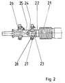
- the fuse consists of a bolt 27 with safety bracket 28, which extends transversely to the longitudinal axis of the coupling rod in a bore in the extension 23 and in a corresponding bore in the rear end 25.
- the coupling rod known per se is provided with a spring part 31 and a cylindrical extension 33 is arranged at the front end 32 of the coupling rod, which extends into a recess 34 in a short piece 35 of a push rod 36.
- the fit is relatively tight.
- the fuse consists of a bolt 37 which penetrates the extension 33 and the bumper 36 transversely to the push rod 36 and which is secured by a bracket 38.
- a buffer plate 39 is welded to the bumper or fastened by other means known per se. The size of this buffer plate 39 can be adapted to the circumstances and also as large as the opening in the car body
Landscapes
- Engineering & Computer Science (AREA)
- Mechanical Engineering (AREA)
- Vibration Dampers (AREA)
- Platform Screen Doors And Railroad Systems (AREA)
- Fittings On The Vehicle Exterior For Carrying Loads, And Devices For Holding Or Mounting Articles (AREA)
- Seal Device For Vehicle (AREA)
Description
- Die Erfindung betrifft ein Wechselsystem für eine Anlenkung an einer Mittelkupplung von Schienenfahrzeugen, wobei die Kuppelstange am einen Ende mit einer an sich bekannten Vorrichtung am Fahrzeug, Drehgestell, Fahrzeugrahmen etc. angelenkt und in der Kuppelstange ein Stossverzehrglied, ein Pufferglied o.ä. angeordnet ist.
- Die bisher bekannten Verbindungen zwischen Kuppelstange und Kuppelkopf bestehen im allgemeinen aus je einem Flansch am Kuppelkopf und an der Kuppelstange, welche dann durch parallel zur Kuppelstange liegende Schrauben fest miteinander verbunden werden. Dies führte aber schon bei geringen Ungenauigkeiten der Schraubenlöcher zur Verlagerung der Kuppelkopfs etc, welche von den Bahngesellschaften nicht akzeptiert werden konnten. Bei der unter dem Namen Albert-Kupplung bekannten Kupplungsart besitzen beide Kuppelköpfe Öffnungen, in die dann ein gemeinsamer Bolzen eingesteckt und gesichert wird. Diese Kupplungsart zeigt aber ein sehr grosses Spiel zwischen den einzelnen Teilen, weshalb diese Kupplung alsbald durch andere Kupplungen ersetzt wurde, die weniger Spiel zwischen den zu kuppelnden Teilen der Vorrichtungen besitzen. Vor allem ist das Wechseln des Kuppelkopfs sehr zeitaufwendig.
- Der vorliegenden Erfindung liegt daher die Aufgabe zugrunde, die Nachteile der bekannten Kupplungen zu vermeiden und das vordere Ende der Kuppelstange so auszubilden, dass nicht nur ein Kuppelkopf leicht angebracht werden kann, sondern auch andere Elemente, wie z.B. eine Pufferplatte, welche in manchen Fällen z.B.beim Rangieren vorteilhaft eingesetzt werden kann.
- Die Lösung dieser Aufgabe besteht darin, dass das andere vordere Ende der Kuppelstange mit einem Fortsatz oder einem Zentriersystem mit Schalenmuffenbund versehen ist, welcher in eine im Kuppelkopfende, in eine eine Pufferplatte tragende Stosstangenende o.ä. vorgesehenen, dem Fortsatz entsprechende Ausnehmung passt und eine Sicherung wie Schalenmuffe, Bolzen mit Bügel etc. vorgesehen ist.
- Vorteilhaft ist der Fortsatz ein Bolzen mit rundem Querschnitt, welcher mit relativ geringem Spiel in die Ausnehmung der Wechselteile passt.
- Der Vorteil dieses Wechselsystems besteht darin, dass mit recht einfachen Mitteln die unterschiedlichsten Vorrichtungen an der Kuppelstange angeordnet werden können, wie z.B. ein Mittelpufferkuppelkopf, eine Pufferplatte, eine Schürze zur Abdeckung der Wagenkastenöffnungen an den beiden Enden des Fahrzeugs, Kurzkupplungen etc. Darüberhinaus kann mit einfachen an sich bekannten Zentriervorrichtungen eine genaue Ausrichtung der Wechselteile erzielt werden. Weiter können die Sicherungselemente wesentlich einfacher und vor allem leichter ausgebildet sein, was zu einer spürbaren Gewichtsverringerung des Fahrzeugs führen kann.
- In den Zeichnungen sind beispielsweise Ausführungsformen der Erfindung dargestellt und zwar zeigt :
- Figur 1
- eine Seitenansicht des vorderen Endes einer Kuppelstange,
- Figur 2
- mit einem Mittelpufferkupplungskuppelkopf,
- Figur 2
- einen anderen Kuppelkopf,
- Figur 3
- eine Pufferplatte.
- Figur 1 zeigt das vordere Ende einer Kuppelstange mit einem unter einem Faltenbalg verborgenen Federteil 11, aus dem nach vorne das vordere Ende 12 der Kuppelstange vorsteht und an dem ein zylindrischer Fortsatz 13 angeordnet ist, welcher sich in eine Ausnehmung 14 im hinteren Ende 15 des Kuppelkopfs 16 erstreckt. Die Passung ist relativ grob und zur Sicherung dass sich die Verbindung von Stosstange 12 und Kuppelkopf 16 nicht lösen kann, ist eine Schalenmuffe 17 vorgesehen, welche den am Ende 12 und am Ende des Kuppelkopfs 16 angeordneten Flansch umfasst. Die Schalenmuffe 17 kann auch mit einem Schnellverschluss bekannter Bauart versehen sein.
- In Fig. 2 ist ebenfalls eine Kuppelstange mit Federteil 21 dargestellt, wobei das vordere Ende 22 der Kuppelstange einen Fortsatz 23 mit rundem Querschnitt trägt, welcher sich in eine entsprechende Ausnehmung 24 am hinteren Ende 25 des Kuppelkopf 26 erstreckt, wobei die Passung recht gering ist. Die Sicherung besteht aus einem Bolzen 27 mit Sicherheitsbügel 28, welcher sich quer zur Kuppelstangenlängsachse in eine Bohrung im Fortsatz 23 und in eine korrespondierende Bohrung im hinteren Ende 25 erstreckt.
- Nach Fig.3 ist die an sich bekannte Kuppelstange mit einem Federteil 31 versehen und am vorderen Ende 32 der Kuppelstange ist ein zylindrischer Fortsatz 33 angeordnet, welcher sich in eine Ausnehmung 34 in einem kurzen Stück 35 einer Stosstange 36 erstreckt. Die Passung ist relativ eng. Die Sicherung besteht aus einem Bolzen 37, welcher quer zur Stosstange 36 den Fortsatz 33 und die Stosstange 36 durchdringt und welcher durch einen Bügel 38 gesichert ist. Auf der Vorderseite ist an die Stosstange eine Pufferplatte 39 angeschweisst oder mit anderen an sich bekannten Mitteln befestigt. Die Grösse dieser Pufferplatte 39 kann den Gegebenheiten angepasst werden und auch so gross ein, wie die im Wagenkasten vorhandene Öffnung
Claims (4)
- Wechselsystem für eine Anlenkung an einer Mittelkupplung von Schienenfahrzeugen, wobei die Kuppelstange am einen Ende mit einer an sich bekannten Vorrichtung am Fahrzeug, Drehgestell, Fahrzeugrahmen etc. angelenkt und in der Kuppelstange ein Stossverzehrglied, ein Pufferglied o.ä. angeordnet ist, dadurch gekennzeichnet, dass das andere vordere Ende (12,22,32) der Kuppelstange mit einem Fortsatz (13,23,33) versehen ist, welcher in einen im Kuppelkopfende (15,25) oder in ein eine Pufferplatte (39) tragendes Stosstangenende (35) o.ä. vorgesehenen dem Fortsatz (13,23,33) entsprechende Ausnehmung (14,24,34) passt und eine Sicherung wie Schalenmuffe (17), Bolzen (27,37) mit Bügel (28,38) vorgesehen ist.
- Wechselsystem nach Anspruch 1, dadurch gekennzeichnet, dass die Sicherung am Ende des Fortsatzes angeordnet ist.
- Wechselsystem nach einem der Ansprüche 1 oder 2, dadurch gekennzeichnet, dass der Fortsatz (13,23,33) ein Bolzen mit rundem Querschnitt ist.
- Wechselsystem nach einem der Ansprüche 1 bis 3, dadurch gekennzeichnet, dass zur Festlegung der Wechselteile relativ zur Kuppelstange an sich bekannte Elemente, wie Zentrierstift, Zentriernocken etc. vorgesehen sind.
Priority Applications (1)
| Application Number | Priority Date | Filing Date | Title |
|---|---|---|---|
| AT89115603T ATE88957T1 (de) | 1988-09-09 | 1989-08-24 | Wechselsystem an einer mittelkupplung von schienenfahrzeugen. |
Applications Claiming Priority (2)
| Application Number | Priority Date | Filing Date | Title |
|---|---|---|---|
| DE3830739A DE3830739A1 (de) | 1988-09-09 | 1988-09-09 | Wechselsystem an einer mittelkupplung von schienenfahrzeugen |
| DE3830739 | 1988-09-09 |
Publications (2)
| Publication Number | Publication Date |
|---|---|
| EP0358052A1 EP0358052A1 (de) | 1990-03-14 |
| EP0358052B1 true EP0358052B1 (de) | 1993-05-05 |
Family
ID=6362654
Family Applications (1)
| Application Number | Title | Priority Date | Filing Date |
|---|---|---|---|
| EP89115603A Expired - Lifetime EP0358052B1 (de) | 1988-09-09 | 1989-08-24 | Wechselsystem an einer Mittelkupplung von Schienenfahrzeugen |
Country Status (3)
| Country | Link |
|---|---|
| EP (1) | EP0358052B1 (de) |
| AT (1) | ATE88957T1 (de) |
| DE (2) | DE3830739A1 (de) |
Families Citing this family (5)
| Publication number | Priority date | Publication date | Assignee | Title |
|---|---|---|---|---|
| SE525210C2 (sv) | 2003-05-26 | 2004-12-28 | Dellner Couplers Ab | Muffkoppling för fordonskoppel |
| DE10355640B3 (de) | 2003-11-28 | 2004-11-04 | Voith Turbo Scharfenberg Gmbh & Co. Kg | Mittelpufferkupplung für Schienenfahrzeuge |
| DE102014218484A1 (de) * | 2014-09-15 | 2016-03-17 | Voith Patent Gmbh | Automatische Mittelpufferkupplung der WILLISON -Bauart, insbesondere SA-3 Bauart für Schienenfahrzeuge mit standardisierter Schnittstelle |
| DE102017110325A1 (de) * | 2017-05-12 | 2018-11-15 | Voith Patent Gmbh | Vorrichtung zum lösbaren Verbinden der Endbereiche eines ersten und zweiten hohlzylindrischen Kraftübertragungselements |
| WO2020133309A1 (zh) * | 2018-12-29 | 2020-07-02 | 中车戚墅堰机车车辆工艺研究所有限公司 | 过渡车钩用辅助连挂装置、轨道车辆过渡车钩及轨道车辆 |
Family Cites Families (4)
| Publication number | Priority date | Publication date | Assignee | Title |
|---|---|---|---|---|
| US2656046A (en) * | 1949-07-29 | 1953-10-20 | Carl N Rydin | Mine coupler |
| BE552069A (de) * | 1955-10-25 | |||
| US3246771A (en) * | 1964-09-01 | 1966-04-19 | Cushion Coupler Corp | Cushion couplers for railway cars |
| GB1132705A (en) * | 1965-07-23 | 1968-11-06 | F H Lloyd & Co Ltd | Railway vehicle buff and/or drawgear |
-
1988
- 1988-09-09 DE DE3830739A patent/DE3830739A1/de not_active Withdrawn
-
1989
- 1989-08-24 EP EP89115603A patent/EP0358052B1/de not_active Expired - Lifetime
- 1989-08-24 AT AT89115603T patent/ATE88957T1/de not_active IP Right Cessation
- 1989-08-24 DE DE8989115603T patent/DE58904266D1/de not_active Expired - Fee Related
Also Published As
| Publication number | Publication date |
|---|---|
| DE3830739A1 (de) | 1990-03-22 |
| DE58904266D1 (de) | 1993-06-09 |
| EP0358052A1 (de) | 1990-03-14 |
| ATE88957T1 (de) | 1993-05-15 |
Similar Documents
| Publication | Publication Date | Title |
|---|---|---|
| EP1531117A1 (de) | Zugfahrzeug mit einem insbesondere doppelachsigen Anhänger | |
| EP0358052B1 (de) | Wechselsystem an einer Mittelkupplung von Schienenfahrzeugen | |
| EP3418084A1 (de) | Bus mit einem kuppelbaren übergang | |
| DE2732345C2 (de) | Kuppelvorrichtung | |
| DE60101103T2 (de) | Den Kupplungsstoss aufnehmende Kupplung | |
| DE1291212B (de) | Vorrichtung zur loesbaren und verdrehungssicheren Verbindung der beiden Teile einer Zugstange | |
| DE488970C (de) | Anhaengerkupplung fuer Kraftfahrzeuge | |
| DE3328123A1 (de) | Lastzug mit einer lenkung fuer das anhaengerfahrzeug | |
| DE6910947U (de) | Kupplung zur verbindung von einraedrigen anhaengern mit kraftwagen. | |
| DE4031718A1 (de) | Zweiteiliger kinder-sicherheitssitz | |
| DE69611117T2 (de) | Bewegliches Kopfstück für bimodales Vehikel (Schiene/Strasse) | |
| DE3004885A1 (de) | Anhaenger fuer lastkraftwagen | |
| AT391662B (de) | Zwischenkupplung zum verbinden von fahrzeugen, insbesondere von strassenfahrzeugen | |
| AT219649B (de) | Vorrichtung zur nachträglichen Befestigung einer Mittelpufferkupplung | |
| DE2161793C (de) | Anhängevorrichtung für Kraftfahrzeuge | |
| EP0538893B1 (de) | Sattelzugfahrzeug | |
| DE942068C (de) | Deichsel fuer Anhaengewagen | |
| DE3035922A1 (de) | Zug- und stossvorrichtung fuer eine mittelpufferkupplung eines schienenfahrzeuges | |
| EP0060996A1 (de) | Fahrgestell für Anhänger | |
| DE1938588C3 (de) | Anschlußprofil, das bei Schleppern, Traktoren und Baumaschinen den Kotflügel und dessen Aufbauten trägt | |
| DE2459232C3 (de) | Abschleppvorrichtung für Kraftfahrzeuge | |
| DE3630580A1 (de) | Lagerung des kappenanstellzylinders bei einem schildausbaugestell | |
| EP0563681B1 (de) | Zugeinrichtung für Schienenfahrzeuge | |
| CH656583A5 (en) | Drawbar for trailers | |
| DE4014631C2 (de) | Luftkupplung für Schienenfahrzeuge |
Legal Events
| Date | Code | Title | Description |
|---|---|---|---|
| PUAI | Public reference made under article 153(3) epc to a published international application that has entered the european phase |
Free format text: ORIGINAL CODE: 0009012 |
|
| AK | Designated contracting states |
Kind code of ref document: A1 Designated state(s): AT BE CH DE FR GB IT LI NL SE |
|
| 17P | Request for examination filed |
Effective date: 19900821 |
|
| 17Q | First examination report despatched |
Effective date: 19911220 |
|
| GRAA | (expected) grant |
Free format text: ORIGINAL CODE: 0009210 |
|
| AK | Designated contracting states |
Kind code of ref document: B1 Designated state(s): AT BE CH DE FR GB IT LI NL SE |
|
| PG25 | Lapsed in a contracting state [announced via postgrant information from national office to epo] |
Ref country code: GB Effective date: 19930505 Ref country code: BE Effective date: 19930505 |
|
| REF | Corresponds to: |
Ref document number: 88957 Country of ref document: AT Date of ref document: 19930515 Kind code of ref document: T |
|
| REF | Corresponds to: |
Ref document number: 58904266 Country of ref document: DE Date of ref document: 19930609 |
|
| ITF | It: translation for a ep patent filed | ||
| PGFP | Annual fee paid to national office [announced via postgrant information from national office to epo] |
Ref country code: FR Payment date: 19930811 Year of fee payment: 5 |
|
| PGFP | Annual fee paid to national office [announced via postgrant information from national office to epo] |
Ref country code: SE Payment date: 19930818 Year of fee payment: 5 |
|
| PG25 | Lapsed in a contracting state [announced via postgrant information from national office to epo] |
Ref country code: AT Effective date: 19930824 |
|
| PG25 | Lapsed in a contracting state [announced via postgrant information from national office to epo] |
Ref country code: LI Effective date: 19930831 Ref country code: CH Effective date: 19930831 |
|
| ET | Fr: translation filed | ||
| GBV | Gb: ep patent (uk) treated as always having been void in accordance with gb section 77(7)/1977 [no translation filed] |
Effective date: 19930505 |
|
| PG25 | Lapsed in a contracting state [announced via postgrant information from national office to epo] |
Ref country code: NL Effective date: 19940301 |
|
| PLBE | No opposition filed within time limit |
Free format text: ORIGINAL CODE: 0009261 |
|
| STAA | Information on the status of an ep patent application or granted ep patent |
Free format text: STATUS: NO OPPOSITION FILED WITHIN TIME LIMIT |
|
| NLV4 | Nl: lapsed or anulled due to non-payment of the annual fee | ||
| 26N | No opposition filed | ||
| REG | Reference to a national code |
Ref country code: CH Ref legal event code: PL |
|
| PG25 | Lapsed in a contracting state [announced via postgrant information from national office to epo] |
Ref country code: SE Effective date: 19940825 |
|
| ITTA | It: last paid annual fee | ||
| EAL | Se: european patent in force in sweden |
Ref document number: 89115603.6 |
|
| PG25 | Lapsed in a contracting state [announced via postgrant information from national office to epo] |
Ref country code: FR Effective date: 19950428 |
|
| EUG | Se: european patent has lapsed |
Ref document number: 89115603.6 |
|
| REG | Reference to a national code |
Ref country code: FR Ref legal event code: ST |
|
| PGFP | Annual fee paid to national office [announced via postgrant information from national office to epo] |
Ref country code: DE Payment date: 19950914 Year of fee payment: 7 |
|
| PG25 | Lapsed in a contracting state [announced via postgrant information from national office to epo] |
Ref country code: DE Effective date: 19970501 |
|
| PG25 | Lapsed in a contracting state [announced via postgrant information from national office to epo] |
Ref country code: IT Free format text: LAPSE BECAUSE OF NON-PAYMENT OF DUE FEES;WARNING: LAPSES OF ITALIAN PATENTS WITH EFFECTIVE DATE BEFORE 2007 MAY HAVE OCCURRED AT ANY TIME BEFORE 2007. THE CORRECT EFFECTIVE DATE MAY BE DIFFERENT FROM THE ONE RECORDED. Effective date: 20050824 |