EP0358367A1 - Plate-forme - Google Patents
Plate-forme Download PDFInfo
- Publication number
- EP0358367A1 EP0358367A1 EP89308444A EP89308444A EP0358367A1 EP 0358367 A1 EP0358367 A1 EP 0358367A1 EP 89308444 A EP89308444 A EP 89308444A EP 89308444 A EP89308444 A EP 89308444A EP 0358367 A1 EP0358367 A1 EP 0358367A1
- Authority
- EP
- European Patent Office
- Prior art keywords
- platform
- support
- support members
- platform according
- elements
- Prior art date
- Legal status (The legal status is an assumption and is not a legal conclusion. Google has not performed a legal analysis and makes no representation as to the accuracy of the status listed.)
- Withdrawn
Links
- 239000004794 expanded polystyrene Substances 0.000 claims abstract description 6
- 239000000463 material Substances 0.000 claims description 17
- 230000008093 supporting effect Effects 0.000 claims description 7
- 230000000284 resting effect Effects 0.000 claims description 5
- 239000004033 plastic Substances 0.000 claims description 3
- 229920003023 plastic Polymers 0.000 claims description 3
- 230000000717 retained effect Effects 0.000 claims description 2
- 229910052729 chemical element Inorganic materials 0.000 abstract description 3
- 239000011093 chipboard Substances 0.000 abstract description 2
- 239000011120 plywood Substances 0.000 abstract description 2
- 230000000875 corresponding effect Effects 0.000 description 2
- 229910000831 Steel Inorganic materials 0.000 description 1
- XAGFODPZIPBFFR-UHFFFAOYSA-N aluminium Chemical compound [Al] XAGFODPZIPBFFR-UHFFFAOYSA-N 0.000 description 1
- 229910052782 aluminium Inorganic materials 0.000 description 1
- 239000004411 aluminium Substances 0.000 description 1
- 238000000034 method Methods 0.000 description 1
- 238000012986 modification Methods 0.000 description 1
- 230000004048 modification Effects 0.000 description 1
- 238000009740 moulding (composite fabrication) Methods 0.000 description 1
- 239000010959 steel Substances 0.000 description 1
Images

Classifications
-
- E—FIXED CONSTRUCTIONS
- E04—BUILDING
- E04H—BUILDINGS OR LIKE STRUCTURES FOR PARTICULAR PURPOSES; SWIMMING OR SPLASH BATHS OR POOLS; MASTS; FENCING; TENTS OR CANOPIES, IN GENERAL
- E04H3/00—Buildings or groups of buildings for public or similar purposes; Institutions, e.g. infirmaries or prisons
- E04H3/10—Buildings or groups of buildings for public or similar purposes; Institutions, e.g. infirmaries or prisons for meetings, entertainments, or sports
- E04H3/22—Theatres; Concert halls; Studios for broadcasting, cinematography, television or similar purposes
- E04H3/24—Constructional features of stages
-
- E—FIXED CONSTRUCTIONS
- E04—BUILDING
- E04F—FINISHING WORK ON BUILDINGS, e.g. STAIRS, FLOORS
- E04F15/00—Flooring
- E04F15/02—Flooring or floor layers composed of a number of similar elements
- E04F15/02044—Separate elements for fastening to an underlayer
-
- E—FIXED CONSTRUCTIONS
- E04—BUILDING
- E04F—FINISHING WORK ON BUILDINGS, e.g. STAIRS, FLOORS
- E04F15/00—Flooring
- E04F15/02—Flooring or floor layers composed of a number of similar elements
- E04F15/02044—Separate elements for fastening to an underlayer
- E04F2015/0205—Separate elements for fastening to an underlayer with load-supporting elongated furring elements between the flooring elements and the underlayer
- E04F2015/02055—Separate elements for fastening to an underlayer with load-supporting elongated furring elements between the flooring elements and the underlayer with additional supporting elements between furring elements and underlayer
Definitions
- THE PRESENT INVENTION relates to a platform.
- One embodiment of the invention particularly relates to a working platform or stage primarily intended for use by builders and/or decorators. Whilst the invention will be described with reference to this primary application it should be appreciated that the platform may have other applications. For example, the platform may be used as a stage by actors.
- Another embodiment of the invention may comprise a permanent fixture to be incorporated in a building.
- a platform or stage it is sometimes necessary to erect a platform or stage for use by builders or decorators, the platform or stage being erected inside a building.
- a platform or stage may be constructed on a supporting framework formed from conventional scaffolding tubes and couplers, or formed from scaffold frames. Whilst such a framework may be satisfactory in use, the scaffolding tubes or the scaffold frames may damage the floor upon which the stage or platform is erected. This is clearly inconvenient, especially if the floor is a screeded floor which is subsequently to be tiled, or if the floor is a woodblock floor.
- the present invention seeks to provide a platform or stage which can be erected without damaging the under-lying floor.
- the invention also seeks to provide a staging or platform that can be assembled quickly, at a low cost.
- a platform comprising a plurality of support elements engaging an under-lying floor, a plurality of support members extending between the support elements, the support members supporting directly or indirectly a plurality of panels constituting the upper surface of the said platform, the support elements having at least the part thereof engaging the under-lying floor made from a yieldable material.
- the yieldable material comprises an expanded or foamed plastics material.
- the yieldable material comprises expanded polystyrene.
- each support element is made as an integral element formed of said yieldable material.
- each support element comprises one or more components located one on top of the other, at least the lowest component being formed entirely of said yieldable material.
- the support elements define a substantially regular square array
- the support members comprise first members extending between support elements defining rows of said elements, and transverse support members resting thereon, the sheets forming the surface of said platform resting on the said transverse support members.
- the joints between adjacent sheets which extend parallel to said transverse support members are located immediately above selected ones of said transverse support members.
- transverse support members comprise planks or scaffolding boards.
- each transverse support comprises two superimposed planks or scaffolding boards.
- the said first support members comprise planks or scaffold boards retained in a vertical or "on edge” condition.
- each support element is provided with at least one groove formed in the upper surface thereof, the groove receiving an edge portion of a said plank or scaffold board.
- each support element is provided with two parallel grooves formed in the upper surface thereof, each receiving an edge portion of a respective plank or scaffold board.
- the invention also relates to a platform structure comprising a plurality of platforms as described superimposed one on the other.
- a platform or stage 1 in accordance with the invention comprises a plurality of supporting elements 2 which rest upon an under-lying floor 3.
- the elements 2 form a regular square array.
- the supporting elements in the presently described embodiment of the invention each comprise a single block of a rigid but yieldable expanded or foamed plastics material.
- a suitable material is expanded polystyrene, but other materials having similar properties may be utilised.
- Each element 2 is of regular parallelipidic form.
- Two parallel transverse grooves or slots 4 are formed in the upper face of each block.
- the blocks in each row of blocks are aligned so that the grooves 4 in the upper faces thereof are co-aligned.
- Wooden planks or scaffold boards 5 are inserted edge-wise into the slots 4 to act as support members.
- Each plank 5 is substantially vertical.
- Each plank 5 may extend between two adjacent blocks in the row or may even extend across three or four blocks in the row.
- planks or scaffold boards 6 may be located extending transversely across the tops of the rows of vertical planks 5.
- the planks 6 may be located in super-imposed pairs.
- the horizontal planks 6 extending between the adjacent rows of vertical planks 5 may be staggered.
- panels or sheets 8 of plywood, chipboard or other similar material may be located on top of the horizontal planks 6. It may be necessary for these panels to be staggered slightly, as shown at 9, in view of the stagger of the under-lying supporting planks 6. It is to be appreciated that each join between the panels 8 parallel to the axis of the planks 6 should actually lie immediately over the centre of a plank 6.
- the positioning of the elements 2 may be adjusted within wide limits, but preferably the positioning is such that the elements 2 are able to withstand the load that is to be supported by the platform 1. If the platform is to carry a heavy load the elements 2 should be relatively close together. However, if the platform is only to carry a relatively light load, then the elements 2 may be further apart.
- the supporting members extending between the elements 2 may comprise timber, steel or aluminium beams. It is not essential for these support members to be recessed into grooves in the elements in any way, and thus in certain embodiments, the transverse slots 4 may be omitted.
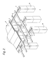
- Figure 2 illustrates an embodiment of the invention which is similar to that illustrated in Figure 1, and like reference numerals apply to like parts.
- each element 2 rests on top of another under-lying block 10, with the block 10 resting upon the floor 3.
- the block 10 is made of expanded polystyrene.
- the the platform of Figure 2 is located higher above the floor than is the platform of Figure 1. It is to be appreciated that the dimension of the elements 2 and the blocks 10 in the vertical direction may be selected to provide a platform having any desired height above the under-lying floor 3.
- the platform or stage may be readily erected in a room of any size. Since the support elements 2 (and the blocks 10) are formed of expanded polystyrene, the load bearing parts of the platform or stage, as represented by the lower parts of the elements 2 and the blocks 10 which actually touch the floor, are of a yieldable material. Thus the stage or platform will not damage an under-lying floor, even if the floor is delicate, such as a woodblock floor.
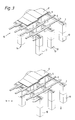
- Figure 3 is a perspective view illustrating a modified embodiment of the invention in which a first platform assembly 11, as described with refernce to Figure 2, rests upon the floor 3, and a second platform assembly 12 rests upon the platform assembly 11.
- the lower-most blocks 10 of the platform assembly 12 may have pairs of transverse grooves 13 formed thereon, to engage the upper edges of the planks 5, thus relatively rigidly inter-connecting the upper platform assembly 12, and the lower platform assembly 11.
- the lower-most blocks 10 of the upper platform assembly 12 may have planar under-surfaces 14, without transverse grooves, and the planar under-surfaces 14 will then just rest on the panels or sheets 8 of the lower platform assembly 11.
- Such a platform may comprise a permanent fitting within a building.
Landscapes
- Engineering & Computer Science (AREA)
- Architecture (AREA)
- Civil Engineering (AREA)
- Structural Engineering (AREA)
- Multimedia (AREA)
- Floor Finish (AREA)
Applications Claiming Priority (2)
| Application Number | Priority Date | Filing Date | Title |
|---|---|---|---|
| GB8819857 | 1988-08-22 | ||
| GB888819857A GB8819857D0 (en) | 1988-08-22 | 1988-08-22 | Improvements in/relating to platform |
Publications (1)
| Publication Number | Publication Date |
|---|---|
| EP0358367A1 true EP0358367A1 (fr) | 1990-03-14 |
Family
ID=10642492
Family Applications (1)
| Application Number | Title | Priority Date | Filing Date |
|---|---|---|---|
| EP89308444A Withdrawn EP0358367A1 (fr) | 1988-08-22 | 1989-08-21 | Plate-forme |
Country Status (2)
| Country | Link |
|---|---|
| EP (1) | EP0358367A1 (fr) |
| GB (1) | GB8819857D0 (fr) |
Cited By (3)
| Publication number | Priority date | Publication date | Assignee | Title |
|---|---|---|---|---|
| EP0517648A1 (fr) * | 1991-06-07 | 1992-12-09 | Peter Riesen | Podium multifonctionnel |
| GB2316974A (en) * | 1996-09-03 | 1998-03-11 | Jonathan Gordon Dyson | Trestle Structure |
| WO2012167899A2 (fr) | 2011-06-10 | 2012-12-13 | Overesch Hubert | Podium transportable |
Citations (5)
| Publication number | Priority date | Publication date | Assignee | Title |
|---|---|---|---|---|
| GB822738A (en) * | 1956-08-15 | 1959-10-28 | Stanley Kermode | Improvements in or relating to floor structures |
| GB1340037A (en) * | 1971-05-24 | 1973-12-05 | Harvey R W S | Raised flooring panels |
| DE2314463A1 (de) * | 1973-03-23 | 1975-02-13 | Winfried Staudenmayer | Bodenplatte |
| GB2126265A (en) * | 1982-08-31 | 1984-03-21 | Contiwood | Adjustable flooring |
| GB2197357A (en) * | 1986-11-07 | 1988-05-18 | Gordon Bramwell Dodson | Staging comprising framing partly nestable within a similar frame |
-
1988
- 1988-08-22 GB GB888819857A patent/GB8819857D0/en active Pending
-
1989
- 1989-08-21 EP EP89308444A patent/EP0358367A1/fr not_active Withdrawn
Patent Citations (5)
| Publication number | Priority date | Publication date | Assignee | Title |
|---|---|---|---|---|
| GB822738A (en) * | 1956-08-15 | 1959-10-28 | Stanley Kermode | Improvements in or relating to floor structures |
| GB1340037A (en) * | 1971-05-24 | 1973-12-05 | Harvey R W S | Raised flooring panels |
| DE2314463A1 (de) * | 1973-03-23 | 1975-02-13 | Winfried Staudenmayer | Bodenplatte |
| GB2126265A (en) * | 1982-08-31 | 1984-03-21 | Contiwood | Adjustable flooring |
| GB2197357A (en) * | 1986-11-07 | 1988-05-18 | Gordon Bramwell Dodson | Staging comprising framing partly nestable within a similar frame |
Cited By (4)
| Publication number | Priority date | Publication date | Assignee | Title |
|---|---|---|---|---|
| EP0517648A1 (fr) * | 1991-06-07 | 1992-12-09 | Peter Riesen | Podium multifonctionnel |
| GB2316974A (en) * | 1996-09-03 | 1998-03-11 | Jonathan Gordon Dyson | Trestle Structure |
| WO2012167899A2 (fr) | 2011-06-10 | 2012-12-13 | Overesch Hubert | Podium transportable |
| DE102011103871A1 (de) | 2011-06-10 | 2012-12-13 | Hubert Overesch | Transportables Bühnenpodest |
Also Published As
| Publication number | Publication date |
|---|---|
| GB8819857D0 (en) | 1988-09-21 |
Similar Documents
| Publication | Publication Date | Title |
|---|---|---|
| EP0228241A2 (fr) | Système de construction | |
| US5333426A (en) | Wood frame construction system with prefabricated components | |
| US7487622B2 (en) | Interlocking frame system for floor and wall structures | |
| US5301486A (en) | Bracing system | |
| US5054580A (en) | Modular walkway system | |
| WO2007142589A1 (fr) | Élément raccord et procédé permettant de raccorder des corps dynamiques à l'aide de l'élément raccord | |
| EP2010375B1 (fr) | Panneau et son utilisation comme planche d'échafaudage ou comme panneau de construction | |
| CA2497711A1 (fr) | Systeme de support structural porteur montable et demontable | |
| AU2001278504B2 (en) | Module for building platforms | |
| GB2161514A (en) | Dance floor | |
| CA2865147A1 (fr) | Trait de scie etendue et mecanisme de limitation de clavette pour surfaces de plancher surelevees | |
| EP0358367A1 (fr) | Plate-forme | |
| DE10006748A1 (de) | Wieder lösbares Verbindungsprofil für Fußbodendielen, Paneele oder ähnliche Bauteile | |
| US11982080B2 (en) | Stack-it bracket | |
| WO2021024019A1 (fr) | Support de plancher surélevé doté d'une tête d'accouplement résistant au vent | |
| WO2012170670A2 (fr) | Panneau de construction et procédés associés | |
| GB2316974A (en) | Trestle Structure | |
| JP2965795B2 (ja) | 建物用床の構築方法 | |
| TWI831137B (zh) | 高架地板收邊結構 | |
| JP7364422B2 (ja) | 床構成ユニット | |
| JPH09189085A (ja) | 建物のパネル構造 | |
| PT8463U (pt) | Estrutura de elemento de superficie de pavimento e/ou assentamento para tribunas (bancada desmontaveis) ou plataformas | |
| JP4227938B2 (ja) | 型枠用補助部材 | |
| JP2561588B2 (ja) | 建物における間仕切りの施工方法 | |
| GB2382837A (en) | Plastic scaffold system |
Legal Events
| Date | Code | Title | Description |
|---|---|---|---|
| PUAI | Public reference made under article 153(3) epc to a published international application that has entered the european phase |
Free format text: ORIGINAL CODE: 0009012 |
|
| AK | Designated contracting states |
Kind code of ref document: A1 Designated state(s): DE FR GB NL SE |
|
| STAA | Information on the status of an ep patent application or granted ep patent |
Free format text: STATUS: THE APPLICATION IS DEEMED TO BE WITHDRAWN |
|
| 18D | Application deemed to be withdrawn |
Effective date: 19900915 |