EP0358397A2 - Ausrüstung eines Progammier-/Zeitschalters mit zweifacher Steuerung - Google Patents
Ausrüstung eines Progammier-/Zeitschalters mit zweifacher Steuerung Download PDFInfo
- Publication number
- EP0358397A2 EP0358397A2 EP89308734A EP89308734A EP0358397A2 EP 0358397 A2 EP0358397 A2 EP 0358397A2 EP 89308734 A EP89308734 A EP 89308734A EP 89308734 A EP89308734 A EP 89308734A EP 0358397 A2 EP0358397 A2 EP 0358397A2
- Authority
- EP
- European Patent Office
- Prior art keywords
- ratchet
- cam
- hub
- pawl
- clutch
- Prior art date
- Legal status (The legal status is an assumption and is not a legal conclusion. Google has not performed a legal analysis and makes no representation as to the accuracy of the status listed.)
- Granted
Links
Images
Classifications
-
- G—PHYSICS
- G05—CONTROLLING; REGULATING
- G05G—CONTROL DEVICES OR SYSTEMS INSOFAR AS CHARACTERISED BY MECHANICAL FEATURES ONLY
- G05G7/00—Manually-actuated control mechanisms provided with one single controlling member co-operating with one single controlled member; Details thereof
- G05G7/02—Manually-actuated control mechanisms provided with one single controlling member co-operating with one single controlled member; Details thereof characterised by special provisions for conveying or converting motion, or for acting at a distance
-
- H—ELECTRICITY
- H01—ELECTRIC ELEMENTS
- H01H—ELECTRIC SWITCHES; RELAYS; SELECTORS; EMERGENCY PROTECTIVE DEVICES
- H01H43/00—Time or time-programme switches providing a choice of time-intervals for executing one or more switching actions and automatically terminating their operation after the programme is completed
- H01H43/10—Time or time-programme switches providing a choice of time-intervals for executing one or more switching actions and automatically terminating their operation after the programme is completed with timing of actuation of contacts due to a part rotating at substantially constant speed
- H01H43/101—Driving mechanisms
-
- H—ELECTRICITY
- H01—ELECTRIC ELEMENTS
- H01H—ELECTRIC SWITCHES; RELAYS; SELECTORS; EMERGENCY PROTECTIVE DEVICES
- H01H43/00—Time or time-programme switches providing a choice of time-intervals for executing one or more switching actions and automatically terminating their operation after the programme is completed
- H01H43/10—Time or time-programme switches providing a choice of time-intervals for executing one or more switching actions and automatically terminating their operation after the programme is completed with timing of actuation of contacts due to a part rotating at substantially constant speed
- H01H43/106—Manual programme selecting means
- H01H2043/107—Bidirectional selecting means, e.g. the programme selecting knob being turnable in both directions
-
- H—ELECTRICITY
- H01—ELECTRIC ELEMENTS
- H01H—ELECTRIC SWITCHES; RELAYS; SELECTORS; EMERGENCY PROTECTIVE DEVICES
- H01H43/00—Time or time-programme switches providing a choice of time-intervals for executing one or more switching actions and automatically terminating their operation after the programme is completed
- H01H43/10—Time or time-programme switches providing a choice of time-intervals for executing one or more switching actions and automatically terminating their operation after the programme is completed with timing of actuation of contacts due to a part rotating at substantially constant speed
- H01H43/101—Driving mechanisms
- H01H43/102—Driving mechanisms using a pawl and ratchet wheel mechanism
-
- Y—GENERAL TAGGING OF NEW TECHNOLOGICAL DEVELOPMENTS; GENERAL TAGGING OF CROSS-SECTIONAL TECHNOLOGIES SPANNING OVER SEVERAL SECTIONS OF THE IPC; TECHNICAL SUBJECTS COVERED BY FORMER USPC CROSS-REFERENCE ART COLLECTIONS [XRACs] AND DIGESTS
- Y10—TECHNICAL SUBJECTS COVERED BY FORMER USPC
- Y10T—TECHNICAL SUBJECTS COVERED BY FORMER US CLASSIFICATION
- Y10T74/00—Machine element or mechanism
- Y10T74/21—Elements
- Y10T74/2101—Cams
- Y10T74/2102—Adjustable
- Y10T74/2106—Timer devices
Definitions
- the present invention relates to electromechanical programmer/timers utilized for sequentially activating at least one and usually a plurality of electrical switches for a selective program interval.
- Programmer/timers of this sort are commonly employed for appliances such as clothes washing machines, dishwashers, microwave ovens and other appliances wherein it is desired for the machine user to select a desired program interval for the appliance operation; and, upon such selection a timing motor provides advancement of a cam track for sequentially actuating the machine control function switches during time-out of the selected interval.
- electromechanical appliance programmer/timers utilize a subfractional horsepower synchronous timer motor driving either a continuous drive to the cam through a speed reducer, or employ an indexing mechanism such as a ratchet wheel engaged by a periodically advanced and retracted pawl.
- an electromechanical programmer/timer for appliance having a ratchet and pawl advance mechanism providing a relatively fast rate of advance and yet also provide for a substantially slower rate of advance with a continuous drive means for a portion of the selected program interval.
- the present invention provides an electromechanical programmer/timer for appliances having a relatively fast rate of advance of the switch cam track provided by an oscillating advance pawl and ratchet wheel and a substantially slower rate of advance provided by a continuous speed reducer drive.
- the ratchet is connected to drive the cam track by a first frictional clutch means and the continuous drive is connected for driving the ratchet by a second frictional clutch means which is permitted to slip when the pawl is engaged for advancing the ratchet.
- the cam track has a portion thereof configured to lift the advanced pawl for the ratchet, thereby disabling the pawl and ratchet advance, whereupon the second frictional clutch ceases to slip and the continuous drive provides for the slower rate of advance.
- User selection of the desired program interval for the cam track is accomplished by user rotation of the cam track which is permitted by slippage of the first and second clutch means to enable the desired positioning of the cam track for commencement of the timed interval for the program.
- the first clutch means comprises a frictional engagement between the interior of the hub on the ratchet wheel and a shaft connected to the cam track.
- a second clutch means comprises a collet provided on the speed reducer aftward gear with the collet frictionally engaging the exterior of the ratchet wheel head.
- the present invention thus provides a novel and simplified instruction for a programmer/timer for appliances wherein a single drive motor is operative to providing a fast rate of advancement through a pawl advancing a ratchet wheel and a slower rate through continuous drive to the ratchet wheel which slips during pawl advancement of the ratchet.
- the slipping clutch Upon lifting of the ratchet, the slipping clutch ceases to slip and provides a slower rate of continuous drive to the cam track.
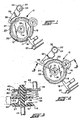
- the dual rate drive mechanism before a programmer/timer is illustrated generally by reference numeral 10 and comprises a drum 12 mounted for rotation about shaft 14 and having a cam track 16 provided about the periphery thereof.
- a cam follower means 18 is pivotally exposed on the base or housing means (not shown) and the follower is engaged in track 16 and is operative to effect actuation and deactuation of the electrical switch mechanism indicated generally at 20.
- the cam drum 12 is shown rotated to a position such that the cam follower 18 rests against the depressed or base circle portion 17 of cam track 16 and in this position effects deactuation of opening of the switch 20.
- cam track 16 on drum 12 disposed generally diameterally opposite the depressed portion 17 is also depressed for a desired arcuate segment of the cam track periphery as indicated by the reference numeral 22.
- a toothed ratchet wheel having teeth 24 of substantially constant pitch and root diameter greater than tracks 22 are formed about the periphery thereof; and, the ratchet 25 is disposed concentrically with respect to shaft 14 and in axially spaced relationship with cam drum 12.
- An advance pawl 26 is provided and has a chisel point 28 disposed to engage the ratchet teeth 24 as illustrated in Figure 1.
- Pawl 26 is connected to orbiting concentric crank pin 30 and has the end thereof opposite to the point 28 disposed over pin 30 and biased thereon by integrally formed spring fingers 34, 32. It will be understood that the crank pin 30 is rotated by a speed reducer and motor drive mechanism (not shown).
- the cam drum 12 is illustrated in the preferred practice as being integrally formed on shaft 14 and is rotated therewith by user rotation of the shaft 14 for positioning the cam track 16 at a desired rotational position with respect to cam follower 18.
- Ratchet wheel 25 is shown in Figure 3 as having an axially extending hub 36 which has the inner periphery thereof received over shaft 14 so as to position the ratchet teeth 24 in alignment for engagement with the pawl chisel point 28.
- the ratchet hub engages the shaft 14 in a frictional engagement and comprises a first frictional clutching means indicated generally by the numeral 37 for operatively connecting the ratchet wheel 25 for rotationally driving cam drum 12.
- the ratchet hub 36 has a reduced diameter extension portion 38 extending from the hub in a direction opposite that of the cam drum 12.
- a speed reducing gear 40 has a central hub 42 provided thereon and received over shaft 14 adjacent the reduced diameter portion 38 of the ratchet hub.
- Gear 40 has peripheral teeth 44 continuously engaged by a motor drive pinion gear 46 which is driven from shaft 48 by a motor comprised (not shown). It will be understood, however, that a common motor drive may be employed with appropriate speed reduction for the eccentric shaft 30 and for the pinion gear 46.
- the hub 42 of gear 40 has provided on the interior thereof a plurality of collet jaws 50 which frictionally engage the exterior of the smaller hub diameter 38 in frictional engagement and comprise a second clutching means indicated generally by reference numeral 51 in Figure 3 for providing a continuous drive from shaft 48 to ratchet wheel 25 via gear 44 and through the first clutching means 31 to the cam drum 12.
- the ratchet wheel 25 is advanced by clutch 51 engaging hub 36 with the pawl chisel point 28 lifted from the ratchet teeth 24 by cam track 52.
- point 28 engages ratchet teeth 24, driving of the ratchet wheel 25.
- the clutch means 51 begins slipping the shaft 14 is driven by clutch 37 at the speed of rotation of the gear 25.
- the drum 12 continues rotating until the cam track 16 reaches the recessed cam track portion 17 whereupon cam follower drops and deactuates or opens switch 20 to cut line power to the motor drive (not shown) for shaft 48.
- the pawl and ratchet drive is operable to provide a faster rotation to cam drive 12 than the continuously rotating pinion gear 46 driving through gear 40 and clutch 51.
- the driving pinion 46 is rotated at a rate of one-fifteenth revolution per minute (1/15 RPM); and, the ration of the number of teeth on pinion 46 to the number of gear teeth 44 is 1:4 giving the gear 40 a rate of rotation of one-sixtieth revolution per minute (1/60 RPM).
- clutch 51 provided with a slippage of break-away torque of forty (40) in-ounces; and, the clutch 37 has a break-away torque of 20 in-ounces.
- shaft 14 may be rotated by the appliance user in either direction. If the pawl 26 is in the position shown in Figure 2, clutch 37 will slip to permit positioning of the cam in either direction. If the pawl is in the position shown in Figure 1, with the chisel point engaging the ratchet teeth, clutch 37 will slip upon user rotation of shaft 14.
- the present invention provides unique and novel dual rate drive for an electromechanical programmer/timer for actuating appliance function switches in a sequence during a selected program interval.
- the programmer/timer of the present invention provides a pawl and ratchet drive to a rotatable switch cam drum in which the ratchet wheel is frictionally clutched to the cam drum shaft; and, the ratchet wheel hub is also separately frictionally clutched to a continuously rotating motor drive gear.
- the friction clutch to the continuously driven gear slips and permits the shaft to be overdriven.
- a cam track lifts the pawl from engagement with the advance ratchet and the shaft is not overdriven and slippage of the gear clutch ceases and the cam drum shaft is driven as a slower rate by the continuously rotated drive gear.
- the pawl engages the ratchet and the drum overdrives the continuously driven gear.
- the user positioning of the cam drum is accomplished by permitting clutch 37 to slip upon user rotation of the cam drum shaft in either direction.
Landscapes
- Physics & Mathematics (AREA)
- General Physics & Mathematics (AREA)
- Engineering & Computer Science (AREA)
- Automation & Control Theory (AREA)
- Measurement Of Predetermined Time Intervals (AREA)
- Transmission Devices (AREA)
- Electromechanical Clocks (AREA)
Applications Claiming Priority (2)
| Application Number | Priority Date | Filing Date | Title |
|---|---|---|---|
| US07/242,397 US4856096A (en) | 1988-09-09 | 1988-09-09 | Providing a programmer/timer with dual rate drive |
| US242397 | 1994-05-13 |
Publications (3)
| Publication Number | Publication Date |
|---|---|
| EP0358397A2 true EP0358397A2 (de) | 1990-03-14 |
| EP0358397A3 EP0358397A3 (de) | 1991-07-03 |
| EP0358397B1 EP0358397B1 (de) | 1995-05-17 |
Family
ID=22914632
Family Applications (1)
| Application Number | Title | Priority Date | Filing Date |
|---|---|---|---|
| EP89308734A Expired - Lifetime EP0358397B1 (de) | 1988-09-09 | 1989-08-30 | Ausrüstung eines Progammier-/Zeitschalters mit zweifacher Steuerung |
Country Status (9)
| Country | Link |
|---|---|
| US (1) | US4856096A (de) |
| EP (1) | EP0358397B1 (de) |
| JP (1) | JPH02135642A (de) |
| KR (1) | KR900005259A (de) |
| AU (1) | AU4117789A (de) |
| BR (1) | BR8904601A (de) |
| DE (1) | DE68922678T2 (de) |
| ES (1) | ES2072303T3 (de) |
| MX (1) | MX168394B (de) |
Cited By (1)
| Publication number | Priority date | Publication date | Assignee | Title |
|---|---|---|---|---|
| EP0518768A1 (de) * | 1991-06-14 | 1992-12-16 | Crouzet Appliance Controls | Schaltgerät für die Programmschalteinrichtung eines elektrischen Haushaltgerät |
Families Citing this family (10)
| Publication number | Priority date | Publication date | Assignee | Title |
|---|---|---|---|---|
| US4945196A (en) * | 1988-09-09 | 1990-07-31 | Eaton Corporation | Providing a programmer/timer with dual rate drive |
| US4980523A (en) * | 1989-07-24 | 1990-12-25 | Eaton Corporation | Appliance programmer/timer with bi-directional drive |
| US5689096A (en) * | 1996-05-28 | 1997-11-18 | Emerson Electric Co. | Cam-operated timer test procedure |
| US5861590A (en) * | 1996-05-28 | 1999-01-19 | Emerson Electric Co. | Cam-operated time quiet cycle selector |
| US5780791A (en) * | 1997-02-24 | 1998-07-14 | Emerson Electric Co. | Timer for controlling an appliance having a plurality of pawls which rotate a camstack |
| US6797897B2 (en) * | 1999-08-02 | 2004-09-28 | France/Scott Fetzer Company | Timer |
| US6080943A (en) * | 1999-08-02 | 2000-06-27 | France/Scott Fetzer Company | Timer |
| US6441326B1 (en) | 1999-08-02 | 2002-08-27 | France/Scott Fetzer Company | Timer |
| US6583371B1 (en) | 2001-11-02 | 2003-06-24 | France/Scott Fetzer Company | Timer |
| GB201710959D0 (en) * | 2017-07-07 | 2017-08-23 | Eaton Srl | Actuator arrangement |
Family Cites Families (5)
| Publication number | Priority date | Publication date | Assignee | Title |
|---|---|---|---|---|
| GB633054A (en) * | 1944-02-05 | 1949-12-12 | British Thomson Houston Co Ltd | Improvements in apparatus for controlling a sequence of operations |
| US3213695A (en) * | 1961-12-21 | 1965-10-26 | Gen Motors Corp | Interval timer and drive mechanism therefor |
| US4366352A (en) * | 1980-08-29 | 1982-12-28 | The Singer Company | Two-speed continuous drive timer |
| US4467664A (en) * | 1981-09-28 | 1984-08-28 | The Singer Company | Timer drive mechanism |
| US4611103A (en) * | 1985-04-11 | 1986-09-09 | Emhart Industries, Inc. | Means providing intermittent motion to a cam means of a timing mechanism and having sub-interval switching means |
-
1988
- 1988-09-09 US US07/242,397 patent/US4856096A/en not_active Expired - Fee Related
-
1989
- 1989-08-30 EP EP89308734A patent/EP0358397B1/de not_active Expired - Lifetime
- 1989-08-30 DE DE68922678T patent/DE68922678T2/de not_active Expired - Fee Related
- 1989-08-30 ES ES89308734T patent/ES2072303T3/es not_active Expired - Lifetime
- 1989-09-08 AU AU41177/89A patent/AU4117789A/en not_active Abandoned
- 1989-09-08 MX MX017490A patent/MX168394B/es unknown
- 1989-09-08 BR BR898904601A patent/BR8904601A/pt unknown
- 1989-09-09 KR KR1019890013063A patent/KR900005259A/ko not_active Withdrawn
- 1989-09-11 JP JP1235488A patent/JPH02135642A/ja active Pending
Cited By (2)
| Publication number | Priority date | Publication date | Assignee | Title |
|---|---|---|---|---|
| EP0518768A1 (de) * | 1991-06-14 | 1992-12-16 | Crouzet Appliance Controls | Schaltgerät für die Programmschalteinrichtung eines elektrischen Haushaltgerät |
| FR2677805A1 (fr) * | 1991-06-14 | 1992-12-18 | Sextant Avionique | Dispositif de commutation pour programmateur d'appareil electrodomestique. |
Also Published As
| Publication number | Publication date |
|---|---|
| AU4117789A (en) | 1990-03-15 |
| JPH02135642A (ja) | 1990-05-24 |
| US4856096A (en) | 1989-08-08 |
| KR900005259A (ko) | 1990-04-13 |
| EP0358397B1 (de) | 1995-05-17 |
| DE68922678D1 (de) | 1995-06-22 |
| EP0358397A3 (de) | 1991-07-03 |
| MX168394B (es) | 1993-05-20 |
| DE68922678T2 (de) | 1996-02-01 |
| BR8904601A (pt) | 1990-04-24 |
| ES2072303T3 (es) | 1995-07-16 |
Similar Documents
| Publication | Publication Date | Title |
|---|---|---|
| US4856096A (en) | Providing a programmer/timer with dual rate drive | |
| EP0124202B1 (de) | Programmierung eines elektrischen Gerätes | |
| US4945196A (en) | Providing a programmer/timer with dual rate drive | |
| EP0360488A2 (de) | Zweirichtungseinstellung eines Programmzeitschaltwerkes | |
| EP0077133B1 (de) | Antriebsvorrichtung für Zeitschalter | |
| EP0410156B1 (de) | Geräte-Programmier-/Zeitschalter mit Zweirichtungsantrieb | |
| JPS62264529A (ja) | 機器コントロ−ルシステム及びそのプログラマ−タイマ− | |
| US3040227A (en) | Timing devices | |
| US4366352A (en) | Two-speed continuous drive timer | |
| US4629845A (en) | Electrical appliance programming | |
| EP0766279A2 (de) | Elektromechanisches Zeitschaltwerk | |
| JP2735360B2 (ja) | マイクロ波オーブンの制御装置 | |
| US6583372B1 (en) | Timer with two speed delay drive system | |
| US4563911A (en) | Programmer control device | |
| GB1369922A (en) | Timing mechanism | |
| GB2030770A (en) | Timing device | |
| JPS60257029A (ja) | プログラムタイマ | |
| SU868204A1 (ru) | Полуоборотный механизм | |
| SU486842A1 (ru) | Устройство дл включени и выключени механизма подачи проволоки в пружиннонавивочном автомате | |
| SU366291A1 (ru) | •сесоюзиая i даш1ш-тгхш1''г-рр; | |
| US6727440B1 (en) | Electromechanical program timer with delay sections | |
| US3081638A (en) | Time control switch mechanism | |
| SU574307A1 (ru) | Привод поворота планшайбы делительного стола | |
| US4592659A (en) | Timer for coin operated devices | |
| FR2446008A1 (fr) | Dispositif de pas a pas pour programmateur electrodomestique |
Legal Events
| Date | Code | Title | Description |
|---|---|---|---|
| PUAI | Public reference made under article 153(3) epc to a published international application that has entered the european phase |
Free format text: ORIGINAL CODE: 0009012 |
|
| AK | Designated contracting states |
Kind code of ref document: A2 Designated state(s): DE ES FR GB IT |
|
| PUAL | Search report despatched |
Free format text: ORIGINAL CODE: 0009013 |
|
| AK | Designated contracting states |
Kind code of ref document: A3 Designated state(s): DE ES FR GB IT |
|
| 17P | Request for examination filed |
Effective date: 19911106 |
|
| 17Q | First examination report despatched |
Effective date: 19931123 |
|
| GRAA | (expected) grant |
Free format text: ORIGINAL CODE: 0009210 |
|
| AK | Designated contracting states |
Kind code of ref document: B1 Designated state(s): DE ES FR GB IT |
|
| REF | Corresponds to: |
Ref document number: 68922678 Country of ref document: DE Date of ref document: 19950622 |
|
| ITF | It: translation for a ep patent filed | ||
| REG | Reference to a national code |
Ref country code: ES Ref legal event code: FG2A Ref document number: 2072303 Country of ref document: ES Kind code of ref document: T3 |
|
| ET | Fr: translation filed | ||
| PG25 | Lapsed in a contracting state [announced via postgrant information from national office to epo] |
Ref country code: GB Effective date: 19950830 |
|
| PG25 | Lapsed in a contracting state [announced via postgrant information from national office to epo] |
Ref country code: ES Free format text: LAPSE BECAUSE OF THE APPLICANT RENOUNCES Effective date: 19950831 |
|
| PLBE | No opposition filed within time limit |
Free format text: ORIGINAL CODE: 0009261 |
|
| STAA | Information on the status of an ep patent application or granted ep patent |
Free format text: STATUS: NO OPPOSITION FILED WITHIN TIME LIMIT |
|
| PG25 | Lapsed in a contracting state [announced via postgrant information from national office to epo] |
Ref country code: FR Effective date: 19960430 |
|
| GBPC | Gb: european patent ceased through non-payment of renewal fee |
Effective date: 19950830 |
|
| PG25 | Lapsed in a contracting state [announced via postgrant information from national office to epo] |
Ref country code: DE Effective date: 19960501 |
|
| 26N | No opposition filed | ||
| REG | Reference to a national code |
Ref country code: FR Ref legal event code: ST |
|
| REG | Reference to a national code |
Ref country code: ES Ref legal event code: FD2A Effective date: 19991102 |
|
| PG25 | Lapsed in a contracting state [announced via postgrant information from national office to epo] |
Ref country code: IT Free format text: LAPSE BECAUSE OF NON-PAYMENT OF DUE FEES;WARNING: LAPSES OF ITALIAN PATENTS WITH EFFECTIVE DATE BEFORE 2007 MAY HAVE OCCURRED AT ANY TIME BEFORE 2007. THE CORRECT EFFECTIVE DATE MAY BE DIFFERENT FROM THE ONE RECORDED. Effective date: 20050830 |