EP0358460B1 - Dispositif de tri - Google Patents
Dispositif de tri Download PDFInfo
- Publication number
- EP0358460B1 EP0358460B1 EP89308984A EP89308984A EP0358460B1 EP 0358460 B1 EP0358460 B1 EP 0358460B1 EP 89308984 A EP89308984 A EP 89308984A EP 89308984 A EP89308984 A EP 89308984A EP 0358460 B1 EP0358460 B1 EP 0358460B1
- Authority
- EP
- European Patent Office
- Prior art keywords
- particles
- stream
- light
- windows
- width
- Prior art date
- Legal status (The legal status is an assumption and is not a legal conclusion. Google has not performed a legal analysis and makes no representation as to the accuracy of the status listed.)
- Expired - Lifetime
Links
- 239000002245 particle Substances 0.000 claims abstract description 65
- 239000004973 liquid crystal related substance Substances 0.000 claims abstract description 12
- 230000003287 optical effect Effects 0.000 claims abstract description 4
- 238000001514 detection method Methods 0.000 claims description 20
- 239000010432 diamond Substances 0.000 claims description 8
- 239000013307 optical fiber Substances 0.000 claims description 7
- 229910003460 diamond Inorganic materials 0.000 claims description 5
- 230000000694 effects Effects 0.000 claims description 4
- 239000011236 particulate material Substances 0.000 claims description 3
- 238000000926 separation method Methods 0.000 claims description 2
- 230000005284 excitation Effects 0.000 description 6
- 239000000835 fiber Substances 0.000 description 3
- 230000005855 radiation Effects 0.000 description 3
- 238000004020 luminiscence type Methods 0.000 description 2
- 230000004044 response Effects 0.000 description 2
- 238000012163 sequencing technique Methods 0.000 description 2
- OAICVXFJPJFONN-UHFFFAOYSA-N Phosphorus Chemical compound [P] OAICVXFJPJFONN-UHFFFAOYSA-N 0.000 description 1
- 230000001351 cycling effect Effects 0.000 description 1
- 230000003247 decreasing effect Effects 0.000 description 1
- 230000023077 detection of light stimulus Effects 0.000 description 1
- 238000010586 diagram Methods 0.000 description 1
- BHEPBYXIRTUNPN-UHFFFAOYSA-N hydridophosphorus(.) (triplet) Chemical compound [PH] BHEPBYXIRTUNPN-UHFFFAOYSA-N 0.000 description 1
- 238000000034 method Methods 0.000 description 1
- 239000013618 particulate matter Substances 0.000 description 1
- 230000000135 prohibitive effect Effects 0.000 description 1
- 239000002356 single layer Substances 0.000 description 1
- 238000001228 spectrum Methods 0.000 description 1
- 230000001360 synchronised effect Effects 0.000 description 1
- XLYOFNOQVPJJNP-UHFFFAOYSA-N water Substances O XLYOFNOQVPJJNP-UHFFFAOYSA-N 0.000 description 1
Images

Classifications
-
- B—PERFORMING OPERATIONS; TRANSPORTING
- B07—SEPARATING SOLIDS FROM SOLIDS; SORTING
- B07C—POSTAL SORTING; SORTING INDIVIDUAL ARTICLES, OR BULK MATERIAL FIT TO BE SORTED PIECE-MEAL, e.g. BY PICKING
- B07C5/00—Sorting according to a characteristic or feature of the articles or material being sorted, e.g. by control effected by devices which detect or measure such characteristic or feature; Sorting by manually actuated devices, e.g. switches
- B07C5/34—Sorting according to other particular properties
- B07C5/342—Sorting according to other particular properties according to optical properties, e.g. colour
- B07C5/3425—Sorting according to other particular properties according to optical properties, e.g. colour of granular material, e.g. ore particles, grain
-
- B—PERFORMING OPERATIONS; TRANSPORTING
- B07—SEPARATING SOLIDS FROM SOLIDS; SORTING
- B07C—POSTAL SORTING; SORTING INDIVIDUAL ARTICLES, OR BULK MATERIAL FIT TO BE SORTED PIECE-MEAL, e.g. BY PICKING
- B07C5/00—Sorting according to a characteristic or feature of the articles or material being sorted, e.g. by control effected by devices which detect or measure such characteristic or feature; Sorting by manually actuated devices, e.g. switches
- B07C5/34—Sorting according to other particular properties
- B07C5/342—Sorting according to other particular properties according to optical properties, e.g. colour
- B07C5/3425—Sorting according to other particular properties according to optical properties, e.g. colour of granular material, e.g. ore particles, grain
- B07C5/3427—Sorting according to other particular properties according to optical properties, e.g. colour of granular material, e.g. ore particles, grain by changing or intensifying the optical properties prior to scanning, e.g. by inducing fluorescence under UV or x-radiation, subjecting the material to a chemical reaction
Definitions
- THIS invention relates to a sorting apparatus.
- the particles may, for instance, be subjected to X-radiation in a case where diamonds are to be sorted from gangue.
- a detection zone Downstream of the excitation zone is a detection zone where a series of photomultiplier (PM) tubes are arranged across the width of the belt to detect luminescence in the particles.
- a bank of air blast ejectors is arranged downstream. When a luminescing particle is detected at the detection zone, the appropriate ejector is actuated to issue an air blast which deflects the relevant particle out of the main stream.
- each PM tube and each ejector cover a small area only of the width of the falling stream of particles. If, for instance, the area "seen" by a PM tube is large, an "eject" signal could be issued when any one of a number of particles "seen” by the PM tube is luminescing. Similarly, if the ejector blasts too large an area, non-luminescing particles could also be ejected. With continuing research, the sizes of the ejectors have been decreased with the result that they are able these days to cover smaller areas than was hitherto possible. However the cost of many small PM tubes has proved to be prohibitive, and the present invention seeks to provide an alternative solution to the detection problem.
- Document EP-A-0,064,842 describes apparatus in accordance with the prior art portion of claim 1 for separating infra-red emitting particulate matter from a stream of matter, by line scanning the stream as it passes through a scanning zone, and diverting detected particles, through the use of air blast nozzles.
- the present invention as defined in claim 1, provides individual windows which are selectively openable, whereby the signals from windows open at different times may be processed by the same means.
- Document GB-A-2,176,888 describes apparatus which directs an X-ray beam across a stream of matter on a conveyor belt under which is mounted a phosphorous strip.
- the strip emits light in response to incident radiation and the amount of light depends on the amount of incident radiation.
- Optical fibres pass this light to a multiplexor which sequentially rotates an open window by the end of each fibre to detect the amount of light passing through each one and correspondingly the amount of radiation incident on each section of the phosphor strip. It contains no suggestion of the simple use of a plurality of controllable windows as used in the present invention.
- the invention provides light detection apparatus according to the appended claim 1.
- each optical fibre is associated with a single window
- each window can pass light from a single width zone only of the stream and the switching means operates such that only one window is open at any given moment.
- the windows may be in an array extending across the width of the stream and the switching means may operate such that every window is open for a portion of the time taken for a particle in the stream to pass the array.
- the invention extends to a particulate material sorting apparatus which comprises light detection apparatus of the kind summarised above.
- the sorting apparatus may comprise means for moving the particles, in a stream, in a direction transverse to the width of the stream and separation means responsive to the processing means for separating from other particles desired particles which emit light detected by the light detection means.
- the light detection apparatus and sorting apparatus are used to sort particles, typically diamond particles, which luminesce under the effects of incident X-radiation from other particles.
- particles typically diamond particles
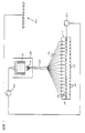
- a stream of particles 10, being diamond and gangue particles, is conveyed on a belt or chute 12, the direction of movement of the stream being into the plane of the paper.
- the stream of particles Immediately preceding its entry into an enclosure 11, the stream of particles has passed through an excitation zone where it is subjected to incident X-radiation or other excitation. Diamond particles in the stream luminesce as a result of this excitation.
- a member 13 Situated just above the stream of particles in the enclosure 11 is a member 13 formed with a series of windows 14 adjacent each of which one end of an optical fibre 19 is located. Each of the windows covers a small width zone of the stream and each of them is controlled by a liquid crystal shutter.
- the various liquid crystal shutters are connected to a control unit 20.
- the unit 20 incorporates a driver unit which, at any given moment, applies a voltage to all of the liquid crystal shutters with the exception of one so that all of the shutters with the exception of that one are opaque.
- a driver unit which, at any given moment, applies a voltage to all of the liquid crystal shutters with the exception of one so that all of the shutters with the exception of that one are opaque.
- the unit 20 furthermore includes the facility for rapidly changing the situation so that all liquid crystal shutters, with the exception of another shutter different to the first shutter, are opaque. In other words, there is only one window 14 which is open at any given time, the window which is open changing continuously and at an extremely rapid rate.
- the optical fibres 19 are arranged in a bundle 22 which extends to a housing 23 in which a photomultiplier tube (PM) tube 21 is situated. The ends of the fibres 19 inside the housing are exposed.
- PM photomultiplier tube
- a window 14 is open, i.e. its associated liquid crystal shutter is transparent, and a particle in the relevant width zone of the stream luminesces, the open window passes the light to the associated optical fibre 19 which conveys the light by total internal reflection to the housing 23, for detection by the PM tube 21.
- FIG. 2 shows the electronic components of the system.
- a clock pulse is applied by a clock oscillator 25 to a liquid crystal drive unit 26 comprising a demultiplexed upcounter which has outputs 27 suitable for applying an appropriate voltage to the liquid crystal shutters 24 associated with the windows 14.
- the voltage is such as to maintain the shutters in a normal dark or opaque state.
- the upcounter sequences it switches one liquid crystal shutter at a time to its transparent state, thus allowing light to pass through the relevant window 14 to the associated optical fibre 19 and, through the fibre 19, to the PM tube 21.
- the PM tube Upon detection of light, the PM tube sends a signal to a signal processing and decision making unit 28 which decides whether the light is indicative of a desired particle in the stream.
- the unit 28 sends an enabling signal to a particle selector sequencing unit 29 comprising a second demultiplexed upcounter cycling synchronously with the driver unit 26.
- the outputs 33 of this counter are enabled by the signal coming from the unit 28 and are connected to a particle selector mechanism (not shown in Figure 2).
- the particle selector mechanism may, for instance, comprise a bank of air blast ejectors 30 ( Figure 1) which is arranged alongside the stream of particles at a downstream location.
- the bank of air blast ejectors will be located alongside the stream of particles after they have been caused to fall in free flight from the belt or chute 12. Then, at the appropriate moment of time, the appropriate ejector is actuated to issue a short duration blast of air which deflects the desired particle from the falling stream for collection apart from other, undesired particles.
- the units 28 and 29 constitute a means (shown diagrammatically at 32 in Figure 1) which acts in response both to the PM tube 21 and, by virtue of the synchronous sequencing, to the instantaneous state of the driver unit 26 to make a decision about which particles are to be selected from the stream of particles.
- a decision is made as to which window 14 was open to pass light detected by the PM tube and accordingly which width zone of the stream contains the light-emitting particle, this decision then enabling the actuation of the correct air blast ejector 30.
- Figure 2 also illustrates the presence of a reset driver 31 to ensure that the circuit starts up synchronously.
- the air blast ejectors each cover the same width of the stream of particles as a lens associated with an optical fibre does. It is then possible to achieve a high degree of accuracy in the ejection zone, so that few non-luminescing particles, if any, are ejected from the stream along with luminescing particles.
- a major advantage of the illustrated apparatus is the fact that there is a requirement for only one PM tube while it is still possible to determine in which width zone of the stream luminescence took place.
- the fibres could, as in the illustrated case, be arranged in a single bundle served by a single PM tube. Alternatively, the fibres could be in different bundles each served by a single PM tube. Even in the latter event, there will still be a relatively small number of PM tubes only.
- the particles are transported through the enclosure 11 on a conveyor belt or chute 12.
- the particles could be falling in free flight after projection from the end of a conveyor.
- the invention is not limited in any way to any particular type of separator in the ejection zone.
- the desired particles could, for instance, be removed from the remainder of the stream by water blasts or by suction means.
- PM tubes for viewing fibres which emanate from the same width zone and which are each fed with a portion of the light given off by a luminescing particle.
- filters for each fibre or a single filter for the PM tube.
- the suitable filter it would be possible to detect diamonds which luminesce in the red part of the spectrum and hence to separate those diamonds from other particles.
Landscapes
- Investigating Or Analysing Materials By Optical Means (AREA)
- Photoreceptors In Electrophotography (AREA)
- Combined Means For Separation Of Solids (AREA)
- Optical Communication System (AREA)
- Sorting Of Articles (AREA)
- Seasonings (AREA)
- Polarising Elements (AREA)
- Investigating Materials By The Use Of Optical Means Adapted For Particular Applications (AREA)
Claims (9)
- Appareil de détection de lumière destiné à déterminer des sections qui, à partir d'une pluralité de sections sur la largeur d'un courant de particules (10), contiennent des particules émettrices de lumière, l'appareil comprenant des moyens de détection de lumière (21), et caractérisé en ce qu'il comprend de plus :(a) une pluralité de fenêtres ouvrables et fermables (14) disposées en opposition à différentes sections sur la largeur du courant de particules (10), chaque fenêtre comprenant un obturateur à cristaux liquides (24) et les fenêtres qui s'ouvrent pouvant laisser passer la lumière émise par les particules dans les sections correspondantes ;(b) des moyens pour commuter les obturateurs à cristaux liquides (24) entre des états de transmission de lumière et des états opaques correspondant respectivement à des états d'ouverture et de fermeture des fenêtres (14) ;(c) une pluralité de fibres optiques (19) associées aux fenêtres et disposées pour transmettre la lumière admise par les fenêtres (14) à destination des moyens de détection des lumières (21) pour sa détection ;(d) des moyens (28,29,32) destinés à identifier une fenêtre (21) qui a admis la lumière détectée par les moyens de détection et de façon correspondante pour identifier une section sur la largeur du courant de particules (10), courant à partir duquel provient la lumière.
- Appareil de détection de lumière selon la revendication 1, caractérisé en ce que chaque fibre optique (19) est associée à une fenêtre unique (14), chaque fenêtre (14) pouvant admettre la lumière à partir d'une section unique seulement, sur la largeur du courant, et les moyens de commutation (20,26) fonctionnent de telle sorte qu'une seule fenêtre (14) est ouverte à tout moment donné.
- Appareil de détection de lumière selon la revendication 1 ou la revendication 2, dans lequel le courant de particules (10) est déplacé dans une direction transversale à la largeur du courant, et caractérisé en ce que les fenêtres (14) se situent dans un ensemble (13) sur la largeur du courant et les moyens de communication (20,26) fonctionnent de façon que chaque fenêtre (14) s'ouvre pendant la fraction de temps nécessaire à une particule (10) dans le courant pour franchir le réseau (13).
- Appareil de détection de lumière selon l'une quelconque des revendications précédentes, cet appareil comprenant un appareil destiné à trier des matières particulaires.
- Appareil selon la revendication 4, comprenant des moyens (12) destinés à déplacer des particules (10), dans un courant, dans une direction transversale à la largeur du courant et des moyens de séparation (30) sensibles aux moyens d'identification (32,28,29) pour séparer à partir d'autres particules (10) les particules (10) qui émettent la lumière détectée par les moyens de détection de lumière (21).
- Appareil selon la revendication 4 ou la revendication 5, comprenant une bande transporteuse (12) destinée à déplacer le courant de particules (10) devant les fenêtres (14).
- Utilisation d'un appareil selon l'une quelconque des revendications 4 à 6, pour trier des particules (10) qui entrent en luminescence sous les effets du rayonnement X incident à partir de particules non luminescentes (10).
- Utilisation d'un appareil selon la revendication 7, pour trier des particules de diamant à partir d'autres particules (10).
- Utilisation d'un appareil de détection de lumière selon l'une quelconque des revendications 1 à 3, pour détecter la lumière émise par les particules de diamant entrant en luminescence sous les effets du rayonnement X incident.
Priority Applications (1)
| Application Number | Priority Date | Filing Date | Title |
|---|---|---|---|
| AT89308984T ATE99196T1 (de) | 1988-09-08 | 1989-09-05 | Sortiervorrichtung. |
Applications Claiming Priority (2)
| Application Number | Priority Date | Filing Date | Title |
|---|---|---|---|
| ZA886679 | 1988-09-08 | ||
| ZA886679 | 1988-09-08 |
Publications (3)
| Publication Number | Publication Date |
|---|---|
| EP0358460A2 EP0358460A2 (fr) | 1990-03-14 |
| EP0358460A3 EP0358460A3 (fr) | 1991-07-31 |
| EP0358460B1 true EP0358460B1 (fr) | 1993-12-29 |
Family
ID=25579407
Family Applications (1)
| Application Number | Title | Priority Date | Filing Date |
|---|---|---|---|
| EP89308984A Expired - Lifetime EP0358460B1 (fr) | 1988-09-08 | 1989-09-05 | Dispositif de tri |
Country Status (6)
| Country | Link |
|---|---|
| US (1) | US4994667A (fr) |
| EP (1) | EP0358460B1 (fr) |
| AT (1) | ATE99196T1 (fr) |
| AU (1) | AU616796B2 (fr) |
| DE (1) | DE68911800T2 (fr) |
| ES (1) | ES2047678T3 (fr) |
Families Citing this family (4)
| Publication number | Priority date | Publication date | Assignee | Title |
|---|---|---|---|---|
| US5753904A (en) * | 1995-12-29 | 1998-05-19 | Motorola, Inc. | Tool for detecting missing balls using a photodetector |
| CN104707807B (zh) * | 2015-03-17 | 2017-05-03 | 项俊俊 | 金刚石刀头自动分类系统和控制策略 |
| CN105137927A (zh) * | 2015-07-30 | 2015-12-09 | 王云丽 | 无干扰光纤信号灯状态采集系统和方法 |
| DE102022121928B4 (de) * | 2022-08-30 | 2025-10-30 | Steinert GmbH | Verfahren bzw. System zum Analysieren von Objekten |
Family Cites Families (16)
| Publication number | Priority date | Publication date | Assignee | Title |
|---|---|---|---|---|
| GB993063A (en) * | 1962-04-30 | 1965-05-26 | Gunsons Sortex Ltd | Photoelectric sorting machine |
| GB1305192A (fr) * | 1969-05-19 | 1973-01-31 | ||
| GB1568366A (en) * | 1976-12-22 | 1980-05-29 | Applied Photophysics Ltd | Apparatus and method for characterising and/or identifying materials using luminescence |
| US4127773A (en) * | 1977-03-31 | 1978-11-28 | Applied Photophysics Limited | Characterizing and identifying materials |
| AU3947278A (en) * | 1978-09-01 | 1980-03-06 | Gunson Sa Ltd | Sorting apparatus |
| US4281765A (en) * | 1979-05-30 | 1981-08-04 | Geosource Inc. | Article-detect signal separating network |
| GB2052736A (en) * | 1979-06-19 | 1981-01-28 | Sphere Invest | Scanning radiation from moving objects |
| EP0064842A1 (fr) * | 1981-05-12 | 1982-11-17 | Sphere Investments Limited | Triage de matériaux |
| ZA831558B (fr) * | 1982-01-27 | 1983-09-30 | ||
| GB2121535B (en) * | 1982-06-02 | 1986-04-30 | Anglo Amer Corp South Africa | Detector for use in sorting system |
| AU562250B2 (en) * | 1982-08-04 | 1987-06-04 | Argyle Diamond Mines Pty. Ltd. | Particle sorting |
| GB2140555B (en) * | 1983-05-24 | 1987-03-25 | British Petroleum Co Plc | Diamond separation |
| GB2176888A (en) * | 1985-06-21 | 1987-01-07 | Goring Kerr Plc | Improvements in or relating to x-ray detection apparatus |
| AU587345B2 (en) * | 1986-08-20 | 1989-08-10 | De Beers Consolidated Mines Limited | Separation process |
| GB2211931B (en) * | 1987-11-02 | 1992-02-26 | De Beers Ind Diamond | Sorting apparatus |
| AU2889289A (en) * | 1988-01-29 | 1989-08-10 | Argyle Diamond Sales Limited | Method of identifying gems |
-
1989
- 1989-09-05 EP EP89308984A patent/EP0358460B1/fr not_active Expired - Lifetime
- 1989-09-05 DE DE89308984T patent/DE68911800T2/de not_active Expired - Fee Related
- 1989-09-05 ES ES89308984T patent/ES2047678T3/es not_active Expired - Lifetime
- 1989-09-05 US US07/402,817 patent/US4994667A/en not_active Expired - Fee Related
- 1989-09-05 AT AT89308984T patent/ATE99196T1/de active
- 1989-09-07 AU AU41137/89A patent/AU616796B2/en not_active Expired
Also Published As
| Publication number | Publication date |
|---|---|
| DE68911800D1 (de) | 1994-02-10 |
| ES2047678T3 (es) | 1994-03-01 |
| ATE99196T1 (de) | 1994-01-15 |
| DE68911800T2 (de) | 1994-04-14 |
| EP0358460A3 (fr) | 1991-07-31 |
| EP0358460A2 (fr) | 1990-03-14 |
| AU616796B2 (en) | 1991-11-07 |
| US4994667A (en) | 1991-02-19 |
| AU4113789A (en) | 1990-03-15 |
Similar Documents
| Publication | Publication Date | Title |
|---|---|---|
| AU716000B2 (en) | High throughput sorting system | |
| EP0789633B1 (fr) | Appareil de tri | |
| US7351929B2 (en) | Method of and apparatus for high speed, high quality, contaminant removal and color sorting of glass cullet | |
| US4136778A (en) | Linen sorter | |
| US5819373A (en) | Apparatus and method for recognizing and separating foreign bodies from fiber in a fiber processing machine | |
| EP0238561B1 (fr) | Trieuse | |
| US5954206A (en) | Optical inspection system | |
| CA2104470C (fr) | Classement ou tri | |
| US4697709A (en) | Sorter for agricultural products | |
| EP0838274A2 (fr) | Systèmes optiques pour dispositif de tri | |
| CN104245159A (zh) | 分选集料 | |
| US3914601A (en) | Compact viewing assembly for light sensitive sorting machine | |
| US5508512A (en) | Sorting machine using dual frequency optical detectors | |
| EP0358460B1 (fr) | Dispositif de tri | |
| WO1993010913A1 (fr) | Separateur de calcin et procede d'utilisation dudit separateur | |
| EP0341096A2 (fr) | Procédé pour identifier des objets ou des domaines individuels | |
| EP0772498B1 (fr) | Systeme de controle optique | |
| US4765484A (en) | Glass sorting apparatus | |
| CN1074947C (zh) | 采用双频率光探测器的分选机 | |
| EP0630693B1 (fr) | Machine de tri comprenant un détecteur de format défectueux | |
| US3750881A (en) | Color sorter | |
| GB2211931A (en) | Sorting particulate material | |
| EP0341092A2 (fr) | Procédé pour identifier des objets ou des domaines spécifiques | |
| CS271568B1 (en) | Device for objects sorting, e.g. solid waste | |
| JPH0231873A (ja) | 角切り野菜の色彩選別機 |
Legal Events
| Date | Code | Title | Description |
|---|---|---|---|
| PUAI | Public reference made under article 153(3) epc to a published international application that has entered the european phase |
Free format text: ORIGINAL CODE: 0009012 |
|
| AK | Designated contracting states |
Kind code of ref document: A2 Designated state(s): AT BE CH DE ES FR GB GR IT LI LU NL SE |
|
| PUAL | Search report despatched |
Free format text: ORIGINAL CODE: 0009013 |
|
| AK | Designated contracting states |
Kind code of ref document: A3 Designated state(s): AT BE CH DE ES FR GB GR IT LI LU NL SE |
|
| 17P | Request for examination filed |
Effective date: 19911125 |
|
| 17Q | First examination report despatched |
Effective date: 19920612 |
|
| GRAA | (expected) grant |
Free format text: ORIGINAL CODE: 0009210 |
|
| AK | Designated contracting states |
Kind code of ref document: B1 Designated state(s): AT BE CH DE ES FR GB GR IT LI LU NL SE |
|
| PG25 | Lapsed in a contracting state [announced via postgrant information from national office to epo] |
Ref country code: GR Free format text: LAPSE BECAUSE OF FAILURE TO SUBMIT A TRANSLATION OF THE DESCRIPTION OR TO PAY THE FEE WITHIN THE PRESCRIBED TIME-LIMIT Effective date: 19931229 |
|
| REF | Corresponds to: |
Ref document number: 99196 Country of ref document: AT Date of ref document: 19940115 Kind code of ref document: T |
|
| ITF | It: translation for a ep patent filed | ||
| REF | Corresponds to: |
Ref document number: 68911800 Country of ref document: DE Date of ref document: 19940210 |
|
| REG | Reference to a national code |
Ref country code: ES Ref legal event code: FG2A Ref document number: 2047678 Country of ref document: ES Kind code of ref document: T3 |
|
| ET | Fr: translation filed | ||
| PGFP | Annual fee paid to national office [announced via postgrant information from national office to epo] |
Ref country code: FR Payment date: 19940615 Year of fee payment: 6 |
|
| PGFP | Annual fee paid to national office [announced via postgrant information from national office to epo] |
Ref country code: SE Payment date: 19940817 Year of fee payment: 6 |
|
| PGFP | Annual fee paid to national office [announced via postgrant information from national office to epo] |
Ref country code: ES Payment date: 19940822 Year of fee payment: 6 |
|
| PGFP | Annual fee paid to national office [announced via postgrant information from national office to epo] |
Ref country code: LU Payment date: 19940901 Year of fee payment: 6 |
|
| PGFP | Annual fee paid to national office [announced via postgrant information from national office to epo] |
Ref country code: CH Payment date: 19940906 Year of fee payment: 6 |
|
| PGFP | Annual fee paid to national office [announced via postgrant information from national office to epo] |
Ref country code: BE Payment date: 19940927 Year of fee payment: 6 |
|
| PGFP | Annual fee paid to national office [announced via postgrant information from national office to epo] |
Ref country code: AT Payment date: 19940928 Year of fee payment: 6 |
|
| PGFP | Annual fee paid to national office [announced via postgrant information from national office to epo] |
Ref country code: NL Payment date: 19940930 Year of fee payment: 6 |
|
| PGFP | Annual fee paid to national office [announced via postgrant information from national office to epo] |
Ref country code: DE Payment date: 19941017 Year of fee payment: 6 |
|
| PLBE | No opposition filed within time limit |
Free format text: ORIGINAL CODE: 0009261 |
|
| STAA | Information on the status of an ep patent application or granted ep patent |
Free format text: STATUS: NO OPPOSITION FILED WITHIN TIME LIMIT |
|
| 26N | No opposition filed | ||
| EAL | Se: european patent in force in sweden |
Ref document number: 89308984.7 |
|
| PG25 | Lapsed in a contracting state [announced via postgrant information from national office to epo] |
Ref country code: AT Effective date: 19950905 Ref country code: LU Free format text: LAPSE BECAUSE OF NON-PAYMENT OF DUE FEES Effective date: 19950905 |
|
| PG25 | Lapsed in a contracting state [announced via postgrant information from national office to epo] |
Ref country code: SE Effective date: 19950906 Ref country code: ES Free format text: LAPSE BECAUSE OF NON-PAYMENT OF DUE FEES Effective date: 19950906 |
|
| PG25 | Lapsed in a contracting state [announced via postgrant information from national office to epo] |
Ref country code: LI Effective date: 19950930 Ref country code: CH Effective date: 19950930 Ref country code: BE Effective date: 19950930 |
|
| BERE | Be: lapsed |
Owner name: DE BEERS INDUSTRIAL DIAMOND DIVISION (PROPRIETARY Effective date: 19950930 |
|
| PG25 | Lapsed in a contracting state [announced via postgrant information from national office to epo] |
Ref country code: NL Effective date: 19960401 |
|
| REG | Reference to a national code |
Ref country code: CH Ref legal event code: PL |
|
| PG25 | Lapsed in a contracting state [announced via postgrant information from national office to epo] |
Ref country code: FR Effective date: 19960531 |
|
| PG25 | Lapsed in a contracting state [announced via postgrant information from national office to epo] |
Ref country code: DE Effective date: 19960601 |
|
| NLV4 | Nl: lapsed or anulled due to non-payment of the annual fee |
Effective date: 19960401 |
|
| EUG | Se: european patent has lapsed |
Ref document number: 89308984.7 |
|
| REG | Reference to a national code |
Ref country code: FR Ref legal event code: ST |
|
| REG | Reference to a national code |
Ref country code: ES Ref legal event code: FD2A Effective date: 19990503 |
|
| REG | Reference to a national code |
Ref country code: GB Ref legal event code: IF02 |
|
| PG25 | Lapsed in a contracting state [announced via postgrant information from national office to epo] |
Ref country code: IT Free format text: LAPSE BECAUSE OF NON-PAYMENT OF DUE FEES Effective date: 20050905 |
|
| PGFP | Annual fee paid to national office [announced via postgrant information from national office to epo] |
Ref country code: GB Payment date: 20080910 Year of fee payment: 20 |
|
| REG | Reference to a national code |
Ref country code: GB Ref legal event code: PE20 Expiry date: 20090904 |
|
| PG25 | Lapsed in a contracting state [announced via postgrant information from national office to epo] |
Ref country code: GB Free format text: LAPSE BECAUSE OF EXPIRATION OF PROTECTION Effective date: 20090904 |