EP0358547A1 - Greif- und Haltevorrichtung für zumindest zwei biegsame Teile, die durch Nähen o.dgl. zusammengefügt werden - Google Patents
Greif- und Haltevorrichtung für zumindest zwei biegsame Teile, die durch Nähen o.dgl. zusammengefügt werden Download PDFInfo
- Publication number
- EP0358547A1 EP0358547A1 EP89402342A EP89402342A EP0358547A1 EP 0358547 A1 EP0358547 A1 EP 0358547A1 EP 89402342 A EP89402342 A EP 89402342A EP 89402342 A EP89402342 A EP 89402342A EP 0358547 A1 EP0358547 A1 EP 0358547A1
- Authority
- EP
- European Patent Office
- Prior art keywords
- support
- mold
- seat
- forming
- aforementioned
- Prior art date
- Legal status (The legal status is an assumption and is not a legal conclusion. Google has not performed a legal analysis and makes no representation as to the accuracy of the status listed.)
- Granted
Links
- 238000009958 sewing Methods 0.000 title claims abstract description 21
- 239000004744 fabric Substances 0.000 claims abstract description 33
- 230000002093 peripheral effect Effects 0.000 claims abstract description 6
- 230000014759 maintenance of location Effects 0.000 claims description 3
- 238000004519 manufacturing process Methods 0.000 abstract 1
- 210000000078 claw Anatomy 0.000 description 1
- 239000012530 fluid Substances 0.000 description 1
- 238000012423 maintenance Methods 0.000 description 1
- 239000000463 material Substances 0.000 description 1
- 238000000034 method Methods 0.000 description 1
- 210000001519 tissue Anatomy 0.000 description 1
- 238000003466 welding Methods 0.000 description 1
- 238000004804 winding Methods 0.000 description 1
Images

Classifications
-
- D—TEXTILES; PAPER
- D05—SEWING; EMBROIDERING; TUFTING
- D05B—SEWING
- D05B11/00—Machines for sewing quilts or mattresses
- D05B11/005—Machines for sewing quilts or mattresses for sewing the edges of mattresses
-
- B—PERFORMING OPERATIONS; TRANSPORTING
- B68—SADDLERY; UPHOLSTERY
- B68G—METHODS, EQUIPMENT, OR MACHINES FOR USE IN UPHOLSTERING; UPHOLSTERY NOT OTHERWISE PROVIDED FOR
- B68G15/00—Auxiliary devices and tools specially for upholstery
- B68G15/005—Worktables or workframes
Definitions
- the present invention relates generally to a device for gripping and holding at least two pieces or sheets of flexible material with a view to their assembly by sewing, welding, or any suitable method.
- It relates more particularly to a device for gripping and holding two pieces of fabric or canvas intended to be assembled by sewing, one of these pieces having to constitute the covering surface of the upper part of a seat of an automobile seat and the another piece of fabric constituting a band surrounding this seat.
- the present invention aims to fill this gap by providing a gripping and holding device achieving the above objective, and this in a reliable and inexpensive manner.
- the invention relates to a device for gripping and holding at least two flexible parts in fabric for example, intended to be assembled by sewing or the like, and one of which forms a covering surface of the upper part of a seat cushion, for example, while the other forms a strip surrounding this seat, characterized in that that it comprises a support forming a mold capable of receiving said surface and said strip and comprising means allowing the peripheral clamping of these two elements by pressing a plate or the like on said support forming mold.
- the periphery of the mold-forming support is provided with a groove or the like capable of receiving the band surrounding the seat and defining, on the interior side of the support, a sole in the shape of the covering surface. from the upper part of the seat, and from the side outside the support, a flange constituting with the periphery of the plate, the aforementioned pinching means.
- the wall of the groove situated on the outside of the support and comprising the abovementioned flange is provided with orifices connected to a source of vacuum allowing the strip surrounding the seat to be pressed against said wall.
- the aforementioned plate can be actuated by a jack mounted articulated on a frame of which the support forming the mold is integral.
- This frame is fixed on a sleeve rotatably mounted on a part with end piece integral with the support forming the mold and capable of being grasped by the pliers of a robot.
- the plate applicable on the sole it is fixed to the frame by means of a bearing.
- connection of the plate to the frame by a bearing, and the connection of the support forming the mold to the frame by means of a sleeve integral with this frame will allow the plate and the support to rotate simultaneously relative to the frame so to automatically assemble the two pieces of fabric by sewing, as will be explained in detail below.
- the device according to this invention comprises indexing means for identifying the relative positions of the support forming the mold and the plate.
- This invention is further characterized by a cable associated with a return means and fixed to the frame to allow in particular the retention of the frame during the simultaneous rotation of the support forming the mold and the plate, this in order to allow assembly by sewing.
- the frame has substantially the shape of a U between the branches of which the mold-forming support and the plate are simultaneously rotatably mounted, the latter being secured, by means of the aforementioned bearing, to one branches of the U articulated on the remaining part of this U.
- the aforementioned sole receiving the piece of fabric intended to cover the upper part of the seat cushion is provided with means, such as for example asperities, preventing any sliding of this piece of fabric.
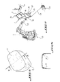
- a gripping and holding device in accordance with this invention essentially comprises a support forming a mold 1 which comprises on the one hand a sole 2 whose external face 2a can receive a piece of fabric, of canvas or the like 3 corresponding to the shape of the upper part of a seat of a vehicle seat for example, and on the other hand of the means 4 allowing the peripheral pinching of the part 3 and of another piece of fabric, canvas or the like 5 to be assembled to the part 3 and constituting a band to surround the seat of the seat (not shown).
- the support forming the mold 1 is provided with a groove or the like 6 capable of receive, in a substantially vertical orientation, the piece of fabric 5 and defining, on the interior side of the support 1, the sole 2 previously mentioned and which is, by its external face 2a, in the shape of the upper surface of the seat of the seat, and on the outside of the support 1, a flange 7 which can cooperate with the periphery 8 of a presser plate 9 so as to pinch the periphery of the pieces of fabric 3 and 5.
- this pinching is carried out a short distance from the peripheral edges of the pieces of fabric 3 and 5 so that these two edges are juxtaposed to form an edge or a fringe 10 which is free and external to the support forming the mold 1, which edge 10 can be sewn by the sewing head shown schematically at 11 in Figure 2 and this in the manner which will be explained later.
- the groove 6 which has substantially a cross section in the shape of a U or a V, comprises, on the inside of the support 1, a wall 6a which in a way constitutes the edge of the sole 2.
- the plate 9, like the mold forming the support 1, are integral with a frame generally identified at 15 and having the general shape of a U, as can be seen in FIGS. 1 and 2.
- One 16 of the branches of the U is articulated at 17 on the remaining part 18 of the U which is itself integral with a sleeve 19 mounted idly on a part 20 fixed on the support forming the mold 1 and carrying at its end an end piece removable 21 allowing the gripping of the entire device by the clamps 22 of a robot 23 visible in FIG. 2.
- the presser plate 9 On the end of the branch 16 of the frame 15 is fixed the presser plate 9 by means of a ball bearing 24, so that said plate can rotate relative to said branch or arm 16.
- a jack 25 is mounted in an articulated manner between the arm 16 and the remaining part 18 of the frame 15, so that, as will be described later in connection with operation, the pressure plate 9 can be moved away from or applied to the sole 2 of the mold support 1.
- Indexing means constituted, according to the example shown, by thrust bearings 27, 28 respectively allow the location of the relative positions of the pressure plate 9 and the support forming the mold 1.
- the outer face 2a of the sole 2 is provided with asperities preventing any sliding of the piece of fabric 3 relative to said sole.
- asperities one could perfectly, without departing from the scope of the invention, use other equivalent means.
- the plate 9-support 1 assembly can rotate simultaneously between the branches of the U constituting the frame 15, and this thanks to the ball bearing 24 and the sleeve bearing 19, it being understood that between this sleeve and the part 20 are provided with seals 31 ensuring airtightness in all the angular positions that the device takes during the operation which will now be described.
- the actuator 25 is actuated which lifts the arm 16 and consequently moves the pressure plate 9 away from the sole 2, so that access inside the mold support 1 is possible
- the operator firstly places the piece of fabric 5 constituting the surrounding of the seat base in the groove 6, taking care to place the outside or appearance of the fabric or the canvas on the side of the wall 6a of said groove, that is to say on the side of the sole 2. Then the operator creates a vacuum in the cavity or chamber 13 which, by means of the orifices 12, causes the part 5 to be held against the wall 6b.
- the piece of fabric 3 is deposited on the sole 2, so that the outer face or aspect of this piece is on the side of the face 2a of the sole 2. It will be specified here that any sliding of the piece of fabric 3 on the sole 2 is avoided by the roughness or other equivalent means, on the face 2a.
- the operator then controls the jack 25 to press the plate 9 on the sole 2 so that the pieces of fabric 3 and 5 are sandwiched by their peripheral edges, and this thanks to the cooperation of the edge 8 of the plate 9 and the rim 7, so as to leave a free edge 10 constituted by two superimposed fringes of part 3 and part 5.
- the robot 23 then grasps the device on the carousel by the end piece 21 and changes the device in front of the sewing head 11, as can be understood by referring to FIG. 2.
- the assembly 9-support plate 1 rotates relative to the frame 15 as the seam is made on the edge 10 formed by the two fringes of the pieces of fabric 3 and 5.
- the cable 29 performs an elastic traction on the frame 15 so as not to interfere with the automatic sewing operation.
- This finished part is then turned over, so as to reveal the outside or appearance of the fabric and to hide the seam, as can be seen in FIG. 4 where the seam is shown diagrammatically at 32.
- the assembly now holding the pieces of fabric to be joined can be fixed, while the sewing head is movable.
- the assembly for gripping and holding the pieces of fabric 3 and 5 can be considered as a fixed station template around which the sewing head moves, which can be animated by a robot.
- the maintenance of the piece of fabric 1 in position can be ensured in various ways, that is to say by using for example the electrostatic properties of this piece of fabric , or by still using a claw mechanism which would be movable inside the sole 2.
Landscapes
- Engineering & Computer Science (AREA)
- Mechanical Engineering (AREA)
- Textile Engineering (AREA)
- Sewing Machines And Sewing (AREA)
Applications Claiming Priority (2)
| Application Number | Priority Date | Filing Date | Title |
|---|---|---|---|
| FR8811755 | 1988-09-08 | ||
| FR8811755A FR2636058B1 (fr) | 1988-09-08 | 1988-09-08 | Dispositif de prehension et maintien d'au moins deux pieces souples en vue de leur assemblage par couture ou analogue |
Publications (2)
| Publication Number | Publication Date |
|---|---|
| EP0358547A1 true EP0358547A1 (de) | 1990-03-14 |
| EP0358547B1 EP0358547B1 (de) | 1993-07-28 |
Family
ID=9369831
Family Applications (1)
| Application Number | Title | Priority Date | Filing Date |
|---|---|---|---|
| EP19890402342 Expired - Lifetime EP0358547B1 (de) | 1988-09-08 | 1989-08-24 | Greif- und Haltevorrichtung für zumindest zwei biegsame Teile, die durch Nähen o.dgl. zusammengefügt werden |
Country Status (3)
| Country | Link |
|---|---|
| EP (1) | EP0358547B1 (de) |
| DE (1) | DE68907826T2 (de) |
| FR (1) | FR2636058B1 (de) |
Cited By (2)
| Publication number | Priority date | Publication date | Assignee | Title |
|---|---|---|---|---|
| WO1997006300A1 (de) * | 1995-08-08 | 1997-02-20 | Moll Automatische Nähsysteme Gmbh | Verfahren und vorrichtung zum bilden dreidimensionaler hüllen |
| CN105129482A (zh) * | 2015-07-16 | 2015-12-09 | 合肥奥瑞数控科技有限公司 | 控制式压布器的固定装置 |
Families Citing this family (3)
| Publication number | Priority date | Publication date | Assignee | Title |
|---|---|---|---|---|
| DE102015200720B4 (de) | 2014-07-02 | 2021-05-20 | Adient Luxembourg Holding S.À R.L. | Zuführeinrichtung und Fertigungsvorrichtung zum Vernähen von Zuschnitten gleicher Kontur |
| CN104724659A (zh) * | 2015-03-20 | 2015-06-24 | 苏州琼派瑞特电子科技有限公司 | 一种装枕芯机 |
| DE102015109103B3 (de) * | 2015-06-09 | 2016-09-29 | Benteler Automobiltechnik Gmbh | Anordnung sowie Verfahren zum Vernähen eines Faserwerkstoffrohlings |
Citations (2)
| Publication number | Priority date | Publication date | Assignee | Title |
|---|---|---|---|---|
| US1460399A (en) * | 1922-05-04 | 1923-07-03 | Derby & Co Inc P | Art of upholstery |
| FR994020A (fr) * | 1944-12-06 | 1951-11-09 | Dispositif de montage pour la couture des pièces de maroquinerie s'assemblant angulairement |
-
1988
- 1988-09-08 FR FR8811755A patent/FR2636058B1/fr not_active Expired - Fee Related
-
1989
- 1989-08-24 DE DE1989607826 patent/DE68907826T2/de not_active Expired - Fee Related
- 1989-08-24 EP EP19890402342 patent/EP0358547B1/de not_active Expired - Lifetime
Patent Citations (2)
| Publication number | Priority date | Publication date | Assignee | Title |
|---|---|---|---|---|
| US1460399A (en) * | 1922-05-04 | 1923-07-03 | Derby & Co Inc P | Art of upholstery |
| FR994020A (fr) * | 1944-12-06 | 1951-11-09 | Dispositif de montage pour la couture des pièces de maroquinerie s'assemblant angulairement |
Cited By (2)
| Publication number | Priority date | Publication date | Assignee | Title |
|---|---|---|---|---|
| WO1997006300A1 (de) * | 1995-08-08 | 1997-02-20 | Moll Automatische Nähsysteme Gmbh | Verfahren und vorrichtung zum bilden dreidimensionaler hüllen |
| CN105129482A (zh) * | 2015-07-16 | 2015-12-09 | 合肥奥瑞数控科技有限公司 | 控制式压布器的固定装置 |
Also Published As
| Publication number | Publication date |
|---|---|
| FR2636058A1 (fr) | 1990-03-09 |
| EP0358547B1 (de) | 1993-07-28 |
| DE68907826D1 (de) | 1993-09-02 |
| DE68907826T2 (de) | 1994-02-10 |
| FR2636058B1 (fr) | 1990-11-30 |
Similar Documents
| Publication | Publication Date | Title |
|---|---|---|
| FR2576865A1 (fr) | Dispositif de levier de frein et plus particulierement pieces de raccordement de cable de frein et de reception de gaine pour ce cable | |
| FR2672834A1 (fr) | Organe de serrage et de prehension. | |
| FR2475105A1 (fr) | Mecanisme formant charniere pour couvercle de coffre de vehicule automobile | |
| FR2729885A1 (fr) | Dispositif de coupe de substrat | |
| EP0358547B1 (de) | Greif- und Haltevorrichtung für zumindest zwei biegsame Teile, die durch Nähen o.dgl. zusammengefügt werden | |
| EP0463952A1 (de) | Verfahren zum Schleifen der Messer eines Drehzylinders und Einstellen des mit ihnen zusammenwirkenden festen Gegenmessers, und Vorrichtung zur Durchführung dieses Verfahrens | |
| EP0242309B1 (de) | Biegepresse mit Schwenkbalken | |
| WO1985001898A1 (fr) | Machine automatique perfectionnee pour cambrer selon une configuration spatiale des elements minces et rectilignes, et notamment des fils metalliques | |
| FR2764254A1 (fr) | Dispositif de marchepied mobile pour un vehicule automobile | |
| FR2641487A1 (fr) | Vehicule porteur a outil pour l'inspection et/ou la maintenance des trous de goujons de la bride porteuse du couvercle d'une cuve ou similaire | |
| FR2606308A1 (fr) | Dispositif automatique de remplacement des electrodes d'un robot de soudage | |
| FR2590955A1 (fr) | Appareil pour la fixation d'agrafes de jonction sur un tapis transporteur ou similaire | |
| EP0296442A1 (de) | Ventil für Vakuumbehälter | |
| EP0726123B1 (de) | Roboterverbundenes Werkzeug zum Montieren von Dichtungsstreifen | |
| EP0734338A1 (de) | Einrichtung zur befestigung eines rades eines motorrades am ständer und leistungsprüfstand dafür | |
| FR2952023A1 (fr) | Dispositif d'assistance pour la pose d'un pare-brise ou similaire | |
| FR2833201A1 (fr) | Dispositif de transfert d'objets industriels entre deux positions | |
| LU86110A1 (fr) | Actionneur pour le mouvement d'un outil et dispositif de transfert de carcasses de bandages pneumatiques utilisant cet actionneur | |
| FR2660219A1 (fr) | Machine a bouteroller. | |
| FR2574334A1 (fr) | Systeme de manipulation de pieces de montage | |
| FR2787063A1 (fr) | Procede de montage d'un pneumatique sur une jante et dispositif pour la mise en oeuvre d'une etape de ce procede | |
| FR2642691A1 (fr) | Appareil destine a etre fixe sur un poignet de robot pour assurer la pose d'un joint de porte | |
| FR2901514A1 (fr) | Accoudoir pour vehicule automobile | |
| FR2708491A1 (fr) | Dispositif de préassemblage de deux pièces à sertir. | |
| FR2612908A1 (fr) | Appareil pour assembler par adherence une housse de garnissage avec une matelassure de siege de vehicule |
Legal Events
| Date | Code | Title | Description |
|---|---|---|---|
| PUAI | Public reference made under article 153(3) epc to a published international application that has entered the european phase |
Free format text: ORIGINAL CODE: 0009012 |
|
| AK | Designated contracting states |
Kind code of ref document: A1 Designated state(s): DE GB IT |
|
| 17P | Request for examination filed |
Effective date: 19900421 |
|
| 17Q | First examination report despatched |
Effective date: 19921229 |
|
| GRAA | (expected) grant |
Free format text: ORIGINAL CODE: 0009210 |
|
| AK | Designated contracting states |
Kind code of ref document: B1 Designated state(s): DE GB IT |
|
| PGFP | Annual fee paid to national office [announced via postgrant information from national office to epo] |
Ref country code: GB Payment date: 19930816 Year of fee payment: 5 |
|
| PGFP | Annual fee paid to national office [announced via postgrant information from national office to epo] |
Ref country code: DE Payment date: 19930823 Year of fee payment: 5 |
|
| REF | Corresponds to: |
Ref document number: 68907826 Country of ref document: DE Date of ref document: 19930902 |
|
| ITF | It: translation for a ep patent filed | ||
| GBT | Gb: translation of ep patent filed (gb section 77(6)(a)/1977) |
Effective date: 19931013 |
|
| PLBE | No opposition filed within time limit |
Free format text: ORIGINAL CODE: 0009261 |
|
| STAA | Information on the status of an ep patent application or granted ep patent |
Free format text: STATUS: NO OPPOSITION FILED WITHIN TIME LIMIT |
|
| 26N | No opposition filed | ||
| PG25 | Lapsed in a contracting state [announced via postgrant information from national office to epo] |
Ref country code: GB Effective date: 19940824 |
|
| GBPC | Gb: european patent ceased through non-payment of renewal fee |
Effective date: 19940824 |
|
| PG25 | Lapsed in a contracting state [announced via postgrant information from national office to epo] |
Ref country code: DE Effective date: 19950503 |
|
| PG25 | Lapsed in a contracting state [announced via postgrant information from national office to epo] |
Ref country code: IT Free format text: LAPSE BECAUSE OF NON-PAYMENT OF DUE FEES;WARNING: LAPSES OF ITALIAN PATENTS WITH EFFECTIVE DATE BEFORE 2007 MAY HAVE OCCURRED AT ANY TIME BEFORE 2007. THE CORRECT EFFECTIVE DATE MAY BE DIFFERENT FROM THE ONE RECORDED. Effective date: 20050824 |