EP0358576A2 - Überwachungsvorrichtung für parkende Autos - Google Patents
Überwachungsvorrichtung für parkende Autos Download PDFInfo
- Publication number
- EP0358576A2 EP0358576A2 EP89402457A EP89402457A EP0358576A2 EP 0358576 A2 EP0358576 A2 EP 0358576A2 EP 89402457 A EP89402457 A EP 89402457A EP 89402457 A EP89402457 A EP 89402457A EP 0358576 A2 EP0358576 A2 EP 0358576A2
- Authority
- EP
- European Patent Office
- Prior art keywords
- vehicle
- detector
- terminal
- alarm means
- cable
- Prior art date
- Legal status (The legal status is an assumption and is not a legal conclusion. Google has not performed a legal analysis and makes no representation as to the accuracy of the status listed.)
- Granted
Links
Images
Classifications
-
- G—PHYSICS
- G08—SIGNALLING
- G08B—SIGNALLING SYSTEMS, e.g. PERSONAL CALLING SYSTEMS; ORDER TELEGRAPHS; ALARM SYSTEMS
- G08B25/00—Alarm systems in which the location of the alarm condition is signalled to a central station, e.g. fire or police telegraphic systems
- G08B25/008—Alarm setting and unsetting, i.e. arming or disarming of the security system
-
- G—PHYSICS
- G07—CHECKING-DEVICES
- G07F—COIN-FREED OR LIKE APPARATUS
- G07F17/00—Coin-freed apparatus for hiring articles; Coin-freed facilities or services
- G07F17/24—Coin-freed apparatus for hiring articles; Coin-freed facilities or services for parking meters
-
- G—PHYSICS
- G08—SIGNALLING
- G08G—TRAFFIC CONTROL SYSTEMS
- G08G1/00—Traffic control systems for road vehicles
- G08G1/14—Traffic control systems for road vehicles indicating individual free spaces in parking areas
Definitions
- the invention relates to a device for monitoring parked vehicles, in particular motor cars in a parking lot. More particularly, the object of the invention is to create a device capable of ensuring the automatic surveillance of vehicles whether or not provided with their own surveillance device, and of reporting any malicious act targeting the vehicle being monitored: attempted break-in, vehicle intrusion, theft, vandalism, etc.
- the monitoring device comprises for this purpose a fixed terminal, arranged near a parking space, a movable detector head connected to the fixed terminal by a flexible cable and designed to be able to be fixed temporarily, inviolably , to a vehicle to be monitored so as to detect possible malicious acts of which it would be the object, an electronic control circuit triggering the operation of alarm means specific to the monitoring device in response to detection signals emitted by the detector head or in the event of severing of the connection cable from the latter to said terminal, and a confidential code device making it possible to authorize and inhibit the triggering of the alarm means.
- Such a device allows each person coming to park their vehicle nearby to place it under surveillance during their absence. It suffices to subject the detector head of the device to its vehicle and to put the latter into activity (standby situation) by introducing a confidential code. To take back his vehicle, the person forms a second confidential code (preferably identical to the first) which puts the device in a situation of inactivity (or waiting); it can then detach the detector head from the vehicle without the device reacting, and the latter is available to monitor another vehicle.
- the detector head has in its structure a part of reduced thickness thanks to which it can be fixed to the vehicle by pinching, at this part, between a fixed element and a mobile element of the vehicle, the operation of this movable element which can be made impossible without break-in to any person not authorized to enter the vehicle.
- the above-mentioned fixed element can be a door frame, the movable element being the door received in this frame, or even a window frame, the movable element being a sliding window in this frame.
- the lesser thickness of the detector head should be the result of a deep slit which the latter comprises, this slit making it possible to mount the detector head on the edge of the sliding glass.
- the detector head may include at least one volumetric ultrasonic or microwave detector (to detect any abnormal movement or displacement inside the vehicle), a shock detector or a change of attitude detector (to detect acts of vandalism and vehicle theft attempts).
- the device for authorizing and inhibiting the triggering of the alarm means can be constituted by a keyboard mounted on the terminal and making it possible to introduce an authorization code into the electronic control circuit and an inhibition code in order to place the device in an active standby situation or return it to a standby situation.
- the fixed terminal may include a safety lock, the only operation of which, using a special key, makes it possible to stop the operation of the alarm means after they have been activated.
- this is done by connecting said terminals at successive points of a single electric cable, which comprises a conductive loop which extends over its entire length and whose opening, revealing a sectioning of the cable, is detected by a control device which then triggers an alarm.
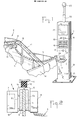
- FIG. 1 a fixed terminal 1 with which a vehicle 2 (automobile) is parked.
- a terminal 4 is connected to terminal 1 by a twisted cable 3 which can be temporarily secured to the vehicle or, when not in use, placed at rest in 4 ′ on a support 5 secured to terminal 1.
- the detector head 4 comprises a U-shaped part 6 on the branches 6a, b of which are fixed externally on the one hand a housing 10 containing a detector 7 and on the other hand a housing 8 of connection to cable 3 and, internally, a pair of blocks 9 of elastic foam offering between them a narrow gap forming a deep slot 24.
- the head 4 is thus composed of two relatively large parts, constituted by the housings 8, 10, which are connected by a thin part formed by the bottom 6c of the U-shaped part 6
- This structure makes it possible to secure the detection head on the vehicle in an inviolable manner by pinching said thin part between the edge of the sliding glass 11 of one of the doors 14 of the vehicle and the corresponding seal 12 which runs the along the frame 13 of the glass in the door.
- the detector 7 is housed in the housing 10 which is inside the vehicle when the detector head 4 is in place.
- This detector is intended to detect attempted break-ins or theft of which the parked vehicle 2 is likely to be the object. It can be a volumetric detector (with ultrasonic, infrared or microwave waves) sensitive to the presence of any moving object or person inside the vehicle, or a shock or attitude change detector , sensitive to the movements of the vehicle as a whole which would result from an attempt to tow or remove the vehicle.
- a volumetric detector with ultrasonic, infrared or microwave waves
- a shock or attitude change detector sensitive to the movements of the vehicle as a whole which would result from an attempt to tow or remove the vehicle.
- several detectors of different types will be combined in the detector head 4.
- the cable 3 ensures the electrical supply, from terminal 1, of the detector or detectors 7 of the head 4 and the routing towards the terminal 1 of the detection signals possibly emitted by the head 4.
- Terminal 1 ( Figure 1) consists of a barrel 21 anchored to the ground by a base 15. On the front face of the barrel 21 appear the support 5 already mentioned, a keyboard 16 with twelve keys, a lock 17 operating using a key, two indicator lights 18, 19 and an information plate 20 for users. At the top of the barrel 21 is mounted a mast 22 carrying at its end a visual alarm device 23 (flashing lamp for example). Terminal 1 also contains an audible alarm device, an electronic control circuit and means of electrical supply or connection to such a supply, not visible in the drawing.
- the keyboard 16 connected to the electronic circuit, comprises ten keys marked 0, 1, ... 9 which allow each user to dial a digital code with several digits at the address of the electronic circuit, as well as a validation key V and a cancel key A for the code entered on the keyboard.
- the two indicators 18 and 19 are also connected to the electronic circuit.
- the indicator 18 is a green indicator, the lighting of which indicates that the monitoring device is available; the indicator 19 is a red indicator which is lit for the entire duration of use of the device.
- the electronic circuit can be a known type of circuit ordinarily used in home monitoring devices. It is designed to trigger the operation of the alarm means if the connection cable 3 comes to be cut.
- the detector head 4 When a motorist wishes to use the monitoring device for his vehicle 2 parked nearby, he enters, after verifying that the green light 18 is on, the detector head 4 resting on the support 5 and subjects it to the vehicle. To do this, it lowers the glass 11 and straddles the head 4 thereon, which takes place in the slot 24 formed between the elastic blocks 9; then it raises the glass so that the thin part 6c of the head 4 is pinched between the edge of the glass and the seal 12. The detector head 4 is then firmly secured to the vehicle, and cannot be removed without it break-in once locked the vehicle doors.
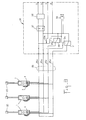
- a monitoring device 1, 3, 4 as described above is installed near each parking space ( Figure 3).
- the terminals 1 of these devices are electrically connected to a common cable 25 for connection to a central station 26.
- This comprises a supply device composed of a storage battery 27 and a charger 28 connected to the AC sector. by a pair of terminals S and ensuring the charge of the battery 27, which supplies, via two wires 25a, 25b of the cable 25, the DC supply voltage necessary for each monitoring device.
- a third wire 25c of the cable 25 routes the alarm signal delivered by the electronic circuit of any of the monitoring devices to the central station 26 and applies this signal to the coil of a relay 29, a contact 29a of which then provides the excitation of an audible alarm means 30, while another contact 29b of this relay applies the voltage of the battery 27 to a pair of terminals P in order to trigger the taking of additional measures such as closing of the gate d access to the car park, switching on of its lighting system, automatic dialing of the telephone number of the nearest police station, etc.
- the cable 25 comprises a fourth wire 25d which, with the supply wire 25a, forms a loop extending over the entire length of the cable.
- This loop connected in series with the coil of a relay 31, a break contact 31a supplies the alarm means 30, ensures the integrity of the cable 25.
- the loop 25a-25d is open, the relay 31 is no longer supplied and its contact 31a closes and controls the operation of the alarm means 30.
- the parking manager is immediately notified by the audible alarm means 30 provided in the central station 26.
- the alarm means specific to each monitoring device, in particular the flashing light 23, immediately indicate to it which vehicle is the object of malicious maneuvers, so that it can take any appropriate measure to put an end to it. He can then stop the emission of alarm signals by actuating the lock 17 of the corresponding terminal 1 using the special key he has, valid for the locks of all the terminals in the car park. Apart from that, the monitoring devices do not require any intervention from the parking manager.
Landscapes
- Physics & Mathematics (AREA)
- General Physics & Mathematics (AREA)
- Engineering & Computer Science (AREA)
- Computer Security & Cryptography (AREA)
- Business, Economics & Management (AREA)
- Emergency Management (AREA)
- Burglar Alarm Systems (AREA)
- Measurement Of Velocity Or Position Using Acoustic Or Ultrasonic Waves (AREA)
- Fittings On The Vehicle Exterior For Carrying Loads, And Devices For Holding Or Mounting Articles (AREA)
- Control Of Motors That Do Not Use Commutators (AREA)
- Devices For Checking Fares Or Tickets At Control Points (AREA)
- Traffic Control Systems (AREA)
Applications Claiming Priority (2)
| Application Number | Priority Date | Filing Date | Title |
|---|---|---|---|
| FR8811835A FR2636457B1 (fr) | 1988-09-09 | 1988-09-09 | Dispositif de surveillance de vehicules en stationnement |
| FR8811835 | 1988-09-09 |
Publications (3)
| Publication Number | Publication Date |
|---|---|
| EP0358576A2 true EP0358576A2 (de) | 1990-03-14 |
| EP0358576A3 EP0358576A3 (de) | 1991-01-30 |
| EP0358576B1 EP0358576B1 (de) | 1994-11-30 |
Family
ID=9369883
Family Applications (1)
| Application Number | Title | Priority Date | Filing Date |
|---|---|---|---|
| EP89402457A Expired - Lifetime EP0358576B1 (de) | 1988-09-09 | 1989-09-08 | Überwachungsvorrichtung für parkende Autos |
Country Status (5)
| Country | Link |
|---|---|
| EP (1) | EP0358576B1 (de) |
| AT (1) | ATE114848T1 (de) |
| DE (1) | DE68919603T2 (de) |
| ES (1) | ES2067562T3 (de) |
| FR (1) | FR2636457B1 (de) |
Family Cites Families (4)
| Publication number | Priority date | Publication date | Assignee | Title |
|---|---|---|---|---|
| US4155067A (en) * | 1977-08-23 | 1979-05-15 | Gleeson Patrick F | Automobile alarm device |
| WO1982002861A1 (en) * | 1981-02-28 | 1982-09-02 | Gunton Bruce Stanley | Security device,motor vehicle incorporating the device and method of indicating an unauthorised attempt to enter an enclosure |
| FR2553047A1 (fr) * | 1983-10-06 | 1985-04-12 | Fournier Jean Robert | Dispositif d'echange d'informations entre un vehicule situe sur une aire de stationnement et une centrale electronique de gestion |
| FR2560624A1 (fr) * | 1984-03-01 | 1985-09-06 | Ferre Jean | Systeme antivol pour parkings pourvu d'un poste central de surveillance |
-
1988
- 1988-09-09 FR FR8811835A patent/FR2636457B1/fr not_active Expired - Fee Related
-
1989
- 1989-09-08 DE DE68919603T patent/DE68919603T2/de not_active Expired - Fee Related
- 1989-09-08 AT AT89402457T patent/ATE114848T1/de not_active IP Right Cessation
- 1989-09-08 EP EP89402457A patent/EP0358576B1/de not_active Expired - Lifetime
- 1989-09-08 ES ES89402457T patent/ES2067562T3/es not_active Expired - Lifetime
Also Published As
| Publication number | Publication date |
|---|---|
| DE68919603D1 (de) | 1995-01-12 |
| EP0358576A3 (de) | 1991-01-30 |
| ES2067562T3 (es) | 1995-04-01 |
| EP0358576B1 (de) | 1994-11-30 |
| FR2636457B1 (fr) | 1994-12-02 |
| DE68919603T2 (de) | 1995-06-01 |
| FR2636457A1 (fr) | 1990-03-16 |
| ATE114848T1 (de) | 1994-12-15 |
Similar Documents
| Publication | Publication Date | Title |
|---|---|---|
| EP0596805B1 (de) | Fernbetätigungssystem zum Sperren und Entsperren von Türen und Öffnungsteilen eines Kraftfahrzeugs | |
| FR2698596A1 (fr) | Système d'enregistrement d'incidents dans un véhicule de transport public de personnes. | |
| FR2848951A1 (fr) | Systeme et procede anti-demarrage pour vehicule, et application de ce systeme pour la gestion d'une flotte de vehicules | |
| EP0460985B1 (de) | Einrichtung zur Überwachung des Verschlusses der Türen eines Autos | |
| FR2541022A1 (fr) | Appareil de telesignalisation | |
| EP0460986B1 (de) | Zentralverriegelung für die Türen eines Autos | |
| FR2560624A1 (fr) | Systeme antivol pour parkings pourvu d'un poste central de surveillance | |
| EP0377700A1 (de) | Verfahren und anordnung zur überwachung von orten, die zum abstellen von objekten verwendet werden | |
| EP0158577B1 (de) | Kontrolleingangsschleuse für Panzerräume | |
| EP3287402B1 (de) | Trommel für verbundenes stromtransportkabel | |
| EP0358576B1 (de) | Überwachungsvorrichtung für parkende Autos | |
| FR2595744A1 (fr) | Cle et serrure electroacoustique correspondante | |
| WO2008023120A2 (fr) | Detecteur de tentative d'effraction de serrure, serrure, porte et systeme d'alarme comportant un tel detecteur | |
| FR2532601A1 (fr) | Appareil pour detecter la presence et surveiller un vehicule gare | |
| FR2651014A1 (fr) | Coffre-fort a serrure a secret | |
| FR2596900A1 (fr) | Dispositif de controle d'acces | |
| EP3870783B1 (de) | System und verfahren zur verhinderung des zugangs zu einem verriegelbaren fach, insbesondere einer sanitärarmatur | |
| BE1027339B1 (fr) | Système de verrouillage d'une porte | |
| FR2741178A1 (fr) | Installation de protection contre le vol pour des vehicules automobiles | |
| FR2661878A1 (fr) | Dispositif antivol pour vehicules automobiles par coupure inviolable de l'alimentation en combustible. | |
| FR2713571A1 (fr) | Dispositif empêchant le vol d'un véhicule automobile que son conducteur aurait laissé portières non verrouillées avec ses clés sur le tableau de bord voire avec le moteur en marche. | |
| FR2733194A1 (fr) | Dispositif antivol de vehicule | |
| EP1551260A2 (de) | Behälter zum lagern von gegenständen | |
| FR2493246A1 (fr) | Appareil automatique de blocage et deblocage des ouvertures, associes a la mise en oeuvre et a l'arret d'un systeme de securite | |
| FR2683931A1 (fr) | Dispositif antivol electromecanique. |
Legal Events
| Date | Code | Title | Description |
|---|---|---|---|
| PUAI | Public reference made under article 153(3) epc to a published international application that has entered the european phase |
Free format text: ORIGINAL CODE: 0009012 |
|
| AK | Designated contracting states |
Kind code of ref document: A2 Designated state(s): AT BE CH DE ES FR GB GR IT LI LU NL SE |
|
| PUAL | Search report despatched |
Free format text: ORIGINAL CODE: 0009013 |
|
| AK | Designated contracting states |
Kind code of ref document: A3 Designated state(s): AT BE CH DE ES FR GB GR IT LI LU NL SE |
|
| 17P | Request for examination filed |
Effective date: 19910612 |
|
| 17Q | First examination report despatched |
Effective date: 19930304 |
|
| GRAA | (expected) grant |
Free format text: ORIGINAL CODE: 0009210 |
|
| AK | Designated contracting states |
Kind code of ref document: B1 Designated state(s): AT BE CH DE ES FR GB GR IT LI LU NL SE |
|
| PG25 | Lapsed in a contracting state [announced via postgrant information from national office to epo] |
Ref country code: NL Effective date: 19941130 Ref country code: GR Free format text: LAPSE BECAUSE OF FAILURE TO SUBMIT A TRANSLATION OF THE DESCRIPTION OR TO PAY THE FEE WITHIN THE PRESCRIBED TIME-LIMIT Effective date: 19941130 Ref country code: AT Effective date: 19941130 |
|
| REF | Corresponds to: |
Ref document number: 114848 Country of ref document: AT Date of ref document: 19941215 Kind code of ref document: T |
|
| REF | Corresponds to: |
Ref document number: 68919603 Country of ref document: DE Date of ref document: 19950112 |
|
| GBT | Gb: translation of ep patent filed (gb section 77(6)(a)/1977) |
Effective date: 19941228 |
|
| ITF | It: translation for a ep patent filed | ||
| PG25 | Lapsed in a contracting state [announced via postgrant information from national office to epo] |
Ref country code: SE Effective date: 19950228 |
|
| REG | Reference to a national code |
Ref country code: ES Ref legal event code: FG2A Ref document number: 2067562 Country of ref document: ES Kind code of ref document: T3 |
|
| NLV1 | Nl: lapsed or annulled due to failure to fulfill the requirements of art. 29p and 29m of the patents act | ||
| PGFP | Annual fee paid to national office [announced via postgrant information from national office to epo] |
Ref country code: GB Payment date: 19950901 Year of fee payment: 7 |
|
| PGFP | Annual fee paid to national office [announced via postgrant information from national office to epo] |
Ref country code: CH Payment date: 19950914 Year of fee payment: 7 |
|
| PGFP | Annual fee paid to national office [announced via postgrant information from national office to epo] |
Ref country code: ES Payment date: 19950919 Year of fee payment: 7 |
|
| PGFP | Annual fee paid to national office [announced via postgrant information from national office to epo] |
Ref country code: DE Payment date: 19950920 Year of fee payment: 7 |
|
| PG25 | Lapsed in a contracting state [announced via postgrant information from national office to epo] |
Ref country code: LU Free format text: LAPSE BECAUSE OF NON-PAYMENT OF DUE FEES Effective date: 19950930 |
|
| PLBE | No opposition filed within time limit |
Free format text: ORIGINAL CODE: 0009261 |
|
| STAA | Information on the status of an ep patent application or granted ep patent |
Free format text: STATUS: NO OPPOSITION FILED WITHIN TIME LIMIT |
|
| PGFP | Annual fee paid to national office [announced via postgrant information from national office to epo] |
Ref country code: BE Payment date: 19951009 Year of fee payment: 7 |
|
| 26N | No opposition filed | ||
| PGFP | Annual fee paid to national office [announced via postgrant information from national office to epo] |
Ref country code: FR Payment date: 19960313 Year of fee payment: 7 |
|
| PG25 | Lapsed in a contracting state [announced via postgrant information from national office to epo] |
Ref country code: GB Effective date: 19960908 |
|
| PG25 | Lapsed in a contracting state [announced via postgrant information from national office to epo] |
Ref country code: ES Free format text: LAPSE BECAUSE OF THE APPLICANT RENOUNCES Effective date: 19960909 |
|
| PG25 | Lapsed in a contracting state [announced via postgrant information from national office to epo] |
Ref country code: LI Effective date: 19960930 Ref country code: FR Effective date: 19960930 Ref country code: CH Effective date: 19960930 Ref country code: BE Effective date: 19960930 |
|
| BERE | Be: lapsed |
Owner name: DERAY ERIC Effective date: 19960930 Owner name: JARROT LAURENT Effective date: 19960930 |
|
| GBPC | Gb: european patent ceased through non-payment of renewal fee |
Effective date: 19960908 |
|
| REG | Reference to a national code |
Ref country code: CH Ref legal event code: PL |
|
| PG25 | Lapsed in a contracting state [announced via postgrant information from national office to epo] |
Ref country code: DE Effective date: 19970603 |
|
| REG | Reference to a national code |
Ref country code: FR Ref legal event code: ST |
|
| REG | Reference to a national code |
Ref country code: FR Ref legal event code: ST |
|
| REG | Reference to a national code |
Ref country code: ES Ref legal event code: FD2A Effective date: 19991007 |
|
| PG25 | Lapsed in a contracting state [announced via postgrant information from national office to epo] |
Ref country code: IT Free format text: LAPSE BECAUSE OF NON-PAYMENT OF DUE FEES Effective date: 20050908 |