EP0358823A2 - Verfahren und Vorrichtung zum Herstellen von Betonplatten mit eingebettetem Glasblock - Google Patents
Verfahren und Vorrichtung zum Herstellen von Betonplatten mit eingebettetem Glasblock Download PDFInfo
- Publication number
- EP0358823A2 EP0358823A2 EP88308510A EP88308510A EP0358823A2 EP 0358823 A2 EP0358823 A2 EP 0358823A2 EP 88308510 A EP88308510 A EP 88308510A EP 88308510 A EP88308510 A EP 88308510A EP 0358823 A2 EP0358823 A2 EP 0358823A2
- Authority
- EP
- European Patent Office
- Prior art keywords
- block
- concrete
- panel
- support
- support form
- Prior art date
- Legal status (The legal status is an assumption and is not a legal conclusion. Google has not performed a legal analysis and makes no representation as to the accuracy of the status listed.)
- Granted
Links
Images

Classifications
-
- E—FIXED CONSTRUCTIONS
- E01—CONSTRUCTION OF ROADS, RAILWAYS, OR BRIDGES
- E01C—CONSTRUCTION OF, OR SURFACES FOR, ROADS, SPORTS GROUNDS, OR THE LIKE; MACHINES OR AUXILIARY TOOLS FOR CONSTRUCTION OR REPAIR
- E01C17/00—Pavement lights, i.e. translucent constructions forming part of the surface
-
- B—PERFORMING OPERATIONS; TRANSPORTING
- B28—WORKING CEMENT, CLAY, OR STONE
- B28B—SHAPING CLAY OR OTHER CERAMIC COMPOSITIONS; SHAPING SLAG; SHAPING MIXTURES CONTAINING CEMENTITIOUS MATERIAL, e.g. PLASTER
- B28B23/00—Arrangements specially adapted for the production of shaped articles with elements wholly or partly embedded in the moulding material; Production of reinforced objects
-
- E—FIXED CONSTRUCTIONS
- E04—BUILDING
- E04C—STRUCTURAL ELEMENTS; BUILDING MATERIALS
- E04C2/00—Building elements of relatively thin form for the construction of parts of buildings, e.g. sheet materials, slabs, or panels
- E04C2/54—Slab-like translucent elements
- E04C2/546—Slab-like translucent elements made of glass bricks
Definitions
- the invention generally relates to methods and apparatus for forming concrete panels with embedded glass block and more particularly relates to methods and apparatus for fabricating such panels in a manner which enhances their ability to resist leaks, bear loads and be transported safely.
- concrete panels which incorporate glass block in a variety of shapes. When shaped like a paving stone or used in a driveway or walkway the glass is often referred to as "paver block". Concrete panels with embedded glass blocks are used in virtually every application where ordinary concrete can be used and is decorative as well as functional. The glass embedded panels in some instances permit the passage of light through an otherwise opaque panel. In many instances the load bearing capacity of the glass embedded panels is important, for example, if a car or truck is to be driven over the panel or if the panel forms a load bearing portion of a structure.
- Jacobs then teaches waterproofing the tile via filling the space between the enclosing ring and the glass lens with brimstone, cement, or other waterproof packing, above a portion of the lens which is flush with the ring.
- the entire combination of ring, lens and sealant are mounted on the separate metal plate to provide support for the combination.
- panel fabricating methods and apparatus which yield a glass embedded panel that does not require a metal support base, holds up well when being handled or transported, is waterproof and is capable of bearing desired, preselected loads.
- Such panel fabricating methods and apparatus are desirable for forming both light transmitting and opaque concrete panels with embedded glass block.
- the invention for constructing a panel form that includes at least one partially anchorable support form. After concrete is poured into the panel form and hardened, the nonanchorable portion of the support form is removed. A noncementitious band (or collar), of which the anchored portion of the support form is comprised, remains. The glass block is then inserted within this band.
- a resilient seal like a rubber gasket, may be inserted between the glass and noncementitious surface to both waterproof the panel and cushion the block to improve the completed panel's ability to be handled and transported without damage.
- the invention teaches utilizing the support form to create at least one support lip.
- Each lip may be formed as part of the anchored band or as part of the formed concrete panel.
- the lip(s) provide a support upon which to rest the block and improve the panel's load bearing capacity.
- a given lip may take any number of shapes and can be designed to take advantage of the inherent load bearing capacity of the concrete in which it is set and/or formed to support the anticipated load. Additional glazing and sealing steps may be optionally performed to further cushion the block and hold it firmly in place.
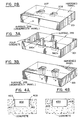
- FIGS. 1a and 1b depict two views of the anchorable portion of a support form suitable for use with the instant invention.
- Unit 101 is a noncementitious band shown in a square configuration to accomodate a square glass block having dimensions that are slightly less than the band.
- the band is made slightly larger then the block to accommodate the insertion of a sealant and possibly filler material between the inserted block and the band.
- Unit 101 is, according to the preferred embodiment of the invention, fabricated from stainless steel.
- the preferred band will have a smooth inner surface and "punchouts", extending outward from the band, to provide anchor hooks to secure the band in the concrete panel poured. These hook punchouts are typified by punchout 102.
- punchout 102 this type of anchor support is for the sake of illustration only. Any variation that locks the band in the concrete is contemplated by the invention described herein. The band's shape may obviously be varied as well.
- FIG. 1b shows a sectional view of band 101, and may be seen to include support lips 103 and 104.
- FIG. 1b shows a sectional view of band 101, and may be seen to include support lips 103 and 104.
- A portion of FIG. 1b labeled "A" constituting the outside of band 101
- concrete poured into the panel, upon hardening, will form a support beam under lip 103.
- the "beam” that will be formed is shown in dotted lines, running around the outside perimeter of band 101, as beam 114.
- FIG. 1b also shows support lip 104 upon which a glass block may be rested.
- the height of the band, together with the degree to which lips 103 and 104 extend from the vertical portion of the band, can be adjusted to provide a predetermined amount of support for the glass block and will obviously be a factor in determining the overall load bearing capacity of the formed panel.
- FIG. 1c depicts another type of anchorable band used as part of a support form contemplated by the invention.
- the only lip extending from the band depicting in FIG. 1c is lip 133.
- Lip 133 corresponds to lip 103 in FIG. 1a, is shaped differently then lip 103, and is an example of a band that may be used in applications where the block itself has independent support.
- the block can be rested on one or more support lips formed in the concrete panel itself after concrete is poured, hardened, and the unanchored portion of the support form is removed.
- the support lips that come in contact with the glass block may be a part of the anchorable portion of the band itself and/or the hardened concrete upon which a block rests once the nonanchorable portion of a support is removed.
- a predetermined panel load bearing capacity can be achieved by selecting the amount of concrete to be positioned underneath a support lip formed by the anchorable portion of the support form and/or by selecting the amount of concrete to be positioned underneath the block itself, one the nonanchorable portion of a support form is removed.
- anchorable bands without support lips.
- the support lips on the anchorable band may be dispensed with altogether.
- FIG. 2a depicts a panel form 201, which may be used to form an opaque concrete panel with embedded glass block.
- the form in this example and the preferred embodiment, comprises a removable wooden perimeter which forms a trough the size and shape of the panel.
- two Styrofoam support forms, 203a and 203b respectively, are shown positioned as desired.
- Forms 203a and 203b are not thru panel forms since an opaque panel is being fabricated. It will be seen hereinafter, referring to FIGS. 4a-4f, that support forms 203a and 203b further comprise an anchorable portion in addition to the Styrofoam nonanchored portion referred to hereinabove.
- Styrofoam is used in accordance with the preferred embodiment of the invention as part of the support forms, this is not intended to be a limiting factor. Any material which is removable after the concrete is poured would be suitable.
- the formed panel can be flipped over to rest on surface 205, created at the top of the trough as originally positioned (see FIGS. 2a and 2b).
- the support forms to the extent they are removable, can be taken out to expose voids 207 and 208 into which glass block may then be inserted.
- the completed opaque panel may obviously be designed to include a differenct number of glass blocks.
- FIG. 3a shows thru trough support forms 380a and 380b which, when the hardened concrete panel is flipped onto surface 355, form cavities within which to place glass block so that the glass rests on the concrete support lip shown as "X", surrounding the block.
- FIG. 3b depicting hardened panel 301, flipped onto surface 355.
- Variations of the support form to create support lips not completely surrounding a block are also contemplated by the invention.
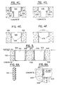
- FIGS. 4a-4f depict cross sections of several different types of support forms contemplated by the invention.
- Each of the support forms depicted in FIGS. 4a-4f are comprised of both the anchorable and nonanchorable portions referred to hereinabove.
- FIG. 4a is depicted as having an anchorable portion, band 401, which surrounds Styrofoam block 402.
- Band 401 is meant to be similar to the band depicted in FIG. 1c, with support lip 403 corresponding to lip 133 of FIG. 1c. Again, with reference to FIG. 4a, it may be seen that support lip 403 could be eliminated since the glass block is shown resting on a concrete base; however, lip 403 may be included to give a metallic finish to the panel surface if the band it is part of is anchored so lip 403 is flush with the surface.
- Styrofoam block 402 is the support form bulk that resists the fluid pressure of the poured concrete to form the cavity in which the glass block to be embedded in the panel will be set.
- Band 401 may be attached to the Styrofoam in any one of a number of ways.
- a channel or groove in, or outward extending nubs from the Styrofoam form, adhesives, etc., are examples of ways to support the band until it is anchored in concrete.
- the Styrofoam block may be removed. The same method applies using any of the support forms described herein.
- FIG. 4a shows band 401 running the full length (vertical) of the Styrofoam block. This is not required by the invention.
- the amount of inner band surface presented toward the glass block face may be varied as desired to accommodate the waterproof, resilient sealant to be inserted therebetween as will be explained hereinafter.
- FIG. 4b depicts an anchor band, 405 without support lips, running partway up the Styrofoam block.
- FIG. 4c and 4d illustrate examples of support forms designed to be utilized in fabricating panels which transmit light. These forms are also illustrated in FIG. 3a and 3b.
- FIG. 4c and 4d are thru panel.
- the thru panel support forms are comprised of Styrofoam blocks which are removable, and anchorable bands of the type described hereinbefore.
- FIG. 4c depicts the support form as the combination of Styrofoam block 422 and anchorable band 423;
- FIG. 4d depicts the support form as the combination of Styrofoam block 432 and anchorable band 433.
- FIG. 4c two support lips are illustrated. One is formed by lip 425 of anchorable band 423; the other is formed by the concrete lip, 426, that will be formed once the cement is poured, hardened and the Styrofoam is removed.
- lip 425 is not actually supporting the glass. As indicated hereinbefore, this lip may be used to provide a metallic finish on the surface of the panel.
- FIG. 4d illustrates using an anchorable band without support lips and once again it may be seen that a concrete lip, 438, will support the block.
- the concrete lip shown in FIGS. 4c and 4d may obviously be varied in size and shape to adjust the support capacity of the panel, by adjusting the size and shape of Styrofoam blocks 422 and 432, respectively.
- FIGS. 4e and 4f illustrate situations where the anchorable band is called upon to actually support the block.
- FIG. 4e depicts the band with support lip 455.
- Styrofoam block shown as 466
- the glass block support lip 455 is shown cut into the Styrofoam block.
- the remainder of the anchorable band, the portion depicted as 456, is affixed in or to the Styrofoam in any of the ways indicated hereinbefore.
- the anchored band and the rigidity of the support lip provide the load bearing capacity for the inserted block.
- This capacity may be increased by using an anchorable band of the type shown in FIG. 1b and illustrated in FIG. 4f as part of a support form.
- the choice of material from which to fabricate the band can also be used to add strength.
- FIG. 4f once the band is set in concrete, support is provided for the block by lips 475 and 476, both part of the anchorable band.
- support lip 476 can be positioned to increase or decrease the height of the concrete "beam" upon which it rests. It should also be noted that the support region may be extended or contracted horizontally as well by adjusting the horizontal length of lip 476.
- FIGS. 4a-4f are for the sake of illustration only.
- the teaching of the invention is that various combinations of anchorable and nonanchorable portions of the support form taught herein may be used to create various types of support lips to bear anticipated loads that may be placed on a completed panel.
- FIG. 5 depicts a cutaway view of a panel and support forms, which accommodate supporting glass block of approximately the same thickness as the panel into which the glass is to be inserted.
- the depicted panel form contains two support forms. In both cases the glass block is to be approximately the same thickness as the panel.
- the lefthand support form, 501 is designed to have a metallic surface finish on surface 512; the righthand support form, 502, is designed to have a concrete finish.
- the support forms used are of the type depicted in FIG. 4f.
- beams that will be formed underneath support lips 505 and 506 respectively, are illustrated by dotted lines and labeled as beam 525 and 526 respectively.
- FIG. 6 illustrates how glass block inserted into a panel form may be cushioned and sealed in accordance with the teachings of the invention.
- FIG. 6a depicts a suitable resilient seal and
- FIG. 6b depicts how the seal depicted in FIG. 6a may be used in combination with glazing and semisolid materials to position, cushion and secure the block.
- Seal 601 shown in FIG. 6a is a rubber gasket. Any resilient sealant will do.
- the purpose of the resilient sealant is to waterproof the panel where the glass and noncementitious band faces oppose one another.
- the resilient seal is to cushion the glass block so as to absorb the shock and stresses asserted on the completed panel when being handled or transported.
- FIG. 6b depicts an example of how further cushioning of a block may be achieved if desired. Additional cushioning material could be placed on concrete support lip 606 upon which the block in FIG. 6b is shown to be resting.
- the cushion would again preferrably be provided by a resilient type of material such as rubber.
- a cushion could also be provided for block lying on a support lip formed by the anchorable band itself as well as block resting on concrete.
- the block may also rest on a glazing compound to further waterproof the joint.
- the compound is shown as 609 in FIG. 6b.
- semisolid material may be injected into any cavity, such as cavity 608 shown in FIG. 6b, to further stabilize the inserted block prior to inserting seal 601.
- the support lips on the anchorable bands could come in a variety of shapes, such as flat top, inverted "U" shape tops, etc., to vary the degree of support provided.
- the resilient seals can come in any number of shapes or sizes, and support forms embodying the principles taught herein can vary in size, shape and composition of materials without departing from the scope of or spirit of the invention.
Landscapes
- Engineering & Computer Science (AREA)
- Architecture (AREA)
- Civil Engineering (AREA)
- Structural Engineering (AREA)
- Manufacturing & Machinery (AREA)
- Chemical & Material Sciences (AREA)
- Ceramic Engineering (AREA)
- Mechanical Engineering (AREA)
- Securing Of Glass Panes Or The Like (AREA)
- Conveying And Assembling Of Building Elements In Situ (AREA)
- On-Site Construction Work That Accompanies The Preparation And Application Of Concrete (AREA)
Priority Applications (4)
| Application Number | Priority Date | Filing Date | Title |
|---|---|---|---|
| US06/866,323 US4779324A (en) | 1986-05-22 | 1986-05-22 | Methods for fabricating concrete panels with embedded glass block |
| CA000572636A CA1317096C (en) | 1986-05-22 | 1988-07-21 | Method and apparatus for fabricating concrete panels with embedded glass block |
| DE8888308510T DE3877572D1 (de) | 1986-05-22 | 1988-09-14 | Verfahren und vorrichtung zum herstellen von betonplatten mit eingebettetem glasblock. |
| EP88308510A EP0358823B1 (de) | 1988-09-14 | 1988-09-14 | Verfahren und Vorrichtung zum Herstellen von Betonplatten mit eingebettetem Glasblock |
Applications Claiming Priority (1)
| Application Number | Priority Date | Filing Date | Title |
|---|---|---|---|
| EP88308510A EP0358823B1 (de) | 1988-09-14 | 1988-09-14 | Verfahren und Vorrichtung zum Herstellen von Betonplatten mit eingebettetem Glasblock |
Publications (3)
| Publication Number | Publication Date |
|---|---|
| EP0358823A2 true EP0358823A2 (de) | 1990-03-21 |
| EP0358823A3 EP0358823A3 (de) | 1991-01-16 |
| EP0358823B1 EP0358823B1 (de) | 1993-01-13 |
Family
ID=8200212
Family Applications (1)
| Application Number | Title | Priority Date | Filing Date |
|---|---|---|---|
| EP88308510A Expired - Lifetime EP0358823B1 (de) | 1986-05-22 | 1988-09-14 | Verfahren und Vorrichtung zum Herstellen von Betonplatten mit eingebettetem Glasblock |
Country Status (1)
| Country | Link |
|---|---|
| EP (1) | EP0358823B1 (de) |
Cited By (1)
| Publication number | Priority date | Publication date | Assignee | Title |
|---|---|---|---|---|
| ES2330492A1 (es) * | 2007-05-31 | 2009-12-10 | Eduardo Ruiz-Risueño Abad | Pieza prefabricada de hormigon y vidrio y proceso para su obtencion. |
Family Cites Families (9)
| Publication number | Priority date | Publication date | Assignee | Title |
|---|---|---|---|---|
| DE510892C (de) * | 1930-10-24 | Felix Valentin | Verfahren zur Herstellung doppelverglaster Bauelemente aus Eiusenbeton | |
| US1821003A (en) * | 1929-06-06 | 1931-09-01 | Robert W Bruner | Skylight construction |
| FR849457A (fr) * | 1938-07-30 | 1939-11-24 | Cie Reunies Glaces Et Verres | Paroi en béton avec éléments transparents ou translucides |
| US2303091A (en) * | 1939-09-11 | 1942-11-24 | Libbey Owens Ford Glass Co | Wall construction |
| GB743059A (en) * | 1952-01-12 | 1956-01-11 | Frank Cunliffe Howarth | Improvements in and relating to former cups for use in pavement or roof lights |
| FR1500249A (fr) * | 1966-09-09 | 1967-11-03 | Menuiseries alvéolaires pour réalisation de panneaux, fixes ouvrants ou mobiles, par enchassement dans les alvéoles de matériaux, transparents, translucides ou opaques | |
| GB1286146A (en) * | 1969-04-01 | 1972-08-23 | Peter Alan Grix | Improved method of and means for forming a cavity when making concrete structures |
| US4629155A (en) * | 1985-03-26 | 1986-12-16 | Dula-Wright, Inc. | In-situ post hole forming device |
| DE3815140C2 (de) * | 1987-05-07 | 2001-03-08 | Oddo Borghetto | Blendrahmen zur Bildung einer Fugenschalung zwecks Verbindung von einzelnen Glasbauelementen |
-
1988
- 1988-09-14 EP EP88308510A patent/EP0358823B1/de not_active Expired - Lifetime
Cited By (2)
| Publication number | Priority date | Publication date | Assignee | Title |
|---|---|---|---|---|
| ES2330492A1 (es) * | 2007-05-31 | 2009-12-10 | Eduardo Ruiz-Risueño Abad | Pieza prefabricada de hormigon y vidrio y proceso para su obtencion. |
| ES2330492B1 (es) * | 2007-05-31 | 2010-06-29 | Eduardo Ruiz-Risueño Abad | Pieza prefabricada de hormigon y vidrio y proceso para su obtencion. |
Also Published As
| Publication number | Publication date |
|---|---|
| EP0358823A3 (de) | 1991-01-16 |
| EP0358823B1 (de) | 1993-01-13 |
Similar Documents
| Publication | Publication Date | Title |
|---|---|---|
| CN110747899B (zh) | 地下室防水施工方法 | |
| US6032421A (en) | Structural blocks for building a basement, block manufacturing method, block transporting method, and block installing method | |
| US4779324A (en) | Methods for fabricating concrete panels with embedded glass block | |
| CA1218551A (en) | Prefabricated pavement module | |
| US4972643A (en) | Concrete panels with embedded block insert | |
| EP0358823B1 (de) | Verfahren und Vorrichtung zum Herstellen von Betonplatten mit eingebettetem Glasblock | |
| US4993208A (en) | Mold for producing tile-shaped floor elements for forming a double floor construction and a corresponding tile-shaped floor element | |
| GB2278384A (en) | Arch bridge constructed by initially positioning an arch former | |
| FI64969B (fi) | Foerfarande foer framstaellning av en sammansatt konstruktion | |
| KR100408895B1 (ko) | 교량의 신축이음 시공방법 | |
| JP2000186329A (ja) | 地下室構造体、その製造方法、その運搬方法およびその施工方法 | |
| SU1281626A1 (ru) | Способ создани противофильтрационной облицовки канала | |
| AU622135B2 (en) | Mould for manufacturing plate-like floor elements for false floors and corresponding plate-like floor elements | |
| BE1012476A3 (nl) | Ruwbouwconstructie, werkwijze voor het vervaardigen daarvan en bouwblok geschikt voor toepassing daarin. | |
| JP3848015B2 (ja) | プリズムガラス用緩衝材及びpcパネル | |
| JPS59187940A (ja) | 開口部を有するコンクリ−ト壁の構築方法 | |
| JPH0211534Y2 (de) | ||
| JPH0337625B2 (de) | ||
| JP3153274B2 (ja) | タイル付軽量気泡コンクリートパネルおよびその製造方法 | |
| JPH0415876Y2 (de) | ||
| SU1330243A1 (ru) | Способ замоноличивани стыков сборных железобетонных элементов в гидротехнических сооружени х | |
| JPH1181209A (ja) | 木質材とコンクリートの複合木レンガ | |
| JPS636709B2 (de) | ||
| GB1588252A (en) | Support frame | |
| JPH111911A (ja) | 支承補修工事用敷き材及び支承補修工事の施工方法 |
Legal Events
| Date | Code | Title | Description |
|---|---|---|---|
| PUAI | Public reference made under article 153(3) epc to a published international application that has entered the european phase |
Free format text: ORIGINAL CODE: 0009012 |
|
| AK | Designated contracting states |
Kind code of ref document: A2 Designated state(s): CH DE FR GB LI |
|
| PUAL | Search report despatched |
Free format text: ORIGINAL CODE: 0009013 |
|
| AK | Designated contracting states |
Kind code of ref document: A3 Designated state(s): CH DE FR GB LI |
|
| 17P | Request for examination filed |
Effective date: 19910711 |
|
| 17Q | First examination report despatched |
Effective date: 19911118 |
|
| GRAA | (expected) grant |
Free format text: ORIGINAL CODE: 0009210 |
|
| AK | Designated contracting states |
Kind code of ref document: B1 Designated state(s): CH DE FR GB LI |
|
| REF | Corresponds to: |
Ref document number: 3877572 Country of ref document: DE Date of ref document: 19930225 |
|
| ET | Fr: translation filed | ||
| PLBE | No opposition filed within time limit |
Free format text: ORIGINAL CODE: 0009261 |
|
| STAA | Information on the status of an ep patent application or granted ep patent |
Free format text: STATUS: NO OPPOSITION FILED WITHIN TIME LIMIT |
|
| 26N | No opposition filed | ||
| PGFP | Annual fee paid to national office [announced via postgrant information from national office to epo] |
Ref country code: GB Payment date: 19960910 Year of fee payment: 9 |
|
| PGFP | Annual fee paid to national office [announced via postgrant information from national office to epo] |
Ref country code: DE Payment date: 19960927 Year of fee payment: 9 |
|
| PGFP | Annual fee paid to national office [announced via postgrant information from national office to epo] |
Ref country code: FR Payment date: 19960930 Year of fee payment: 9 |
|
| PGFP | Annual fee paid to national office [announced via postgrant information from national office to epo] |
Ref country code: CH Payment date: 19961002 Year of fee payment: 9 |
|
| PG25 | Lapsed in a contracting state [announced via postgrant information from national office to epo] |
Ref country code: GB Free format text: LAPSE BECAUSE OF NON-PAYMENT OF DUE FEES Effective date: 19970914 |
|
| PG25 | Lapsed in a contracting state [announced via postgrant information from national office to epo] |
Ref country code: LI Free format text: LAPSE BECAUSE OF NON-PAYMENT OF DUE FEES Effective date: 19970930 Ref country code: FR Free format text: THE PATENT HAS BEEN ANNULLED BY A DECISION OF A NATIONAL AUTHORITY Effective date: 19970930 Ref country code: CH Free format text: LAPSE BECAUSE OF NON-PAYMENT OF DUE FEES Effective date: 19970930 |
|
| GBPC | Gb: european patent ceased through non-payment of renewal fee |
Effective date: 19970914 |
|
| REG | Reference to a national code |
Ref country code: CH Ref legal event code: PL |
|
| PG25 | Lapsed in a contracting state [announced via postgrant information from national office to epo] |
Ref country code: DE Free format text: LAPSE BECAUSE OF NON-PAYMENT OF DUE FEES Effective date: 19980603 |
|
| REG | Reference to a national code |
Ref country code: FR Ref legal event code: ST |