EP0358872A2 - Apparat und Verfahren zum Transportieren eines Werkstückes zwischen zwei Maschinen - Google Patents
Apparat und Verfahren zum Transportieren eines Werkstückes zwischen zwei Maschinen Download PDFInfo
- Publication number
- EP0358872A2 EP0358872A2 EP89112366A EP89112366A EP0358872A2 EP 0358872 A2 EP0358872 A2 EP 0358872A2 EP 89112366 A EP89112366 A EP 89112366A EP 89112366 A EP89112366 A EP 89112366A EP 0358872 A2 EP0358872 A2 EP 0358872A2
- Authority
- EP
- European Patent Office
- Prior art keywords
- bar
- deposit station
- transfer arm
- machine
- gripper
- Prior art date
- Legal status (The legal status is an assumption and is not a legal conclusion. Google has not performed a legal analysis and makes no representation as to the accuracy of the status listed.)
- Withdrawn
Links
- 238000000034 method Methods 0.000 title claims description 12
- 238000012546 transfer Methods 0.000 claims abstract description 77
- 230000007306 turnover Effects 0.000 claims abstract description 33
- 230000007246 mechanism Effects 0.000 claims abstract description 19
- 230000033001 locomotion Effects 0.000 claims description 26
- 238000000151 deposition Methods 0.000 claims description 10
- 230000003578 releasing effect Effects 0.000 claims description 2
- 230000004044 response Effects 0.000 claims description 2
- 239000002184 metal Substances 0.000 abstract description 3
- 238000004519 manufacturing process Methods 0.000 description 5
- 238000013461 design Methods 0.000 description 4
- 230000009471 action Effects 0.000 description 3
- 238000013459 approach Methods 0.000 description 2
- 238000012986 modification Methods 0.000 description 2
- 230000004048 modification Effects 0.000 description 2
- 230000008901 benefit Effects 0.000 description 1
- 230000008859 change Effects 0.000 description 1
- 230000009977 dual effect Effects 0.000 description 1
- 230000002452 interceptive effect Effects 0.000 description 1
Images


Classifications
-
- B—PERFORMING OPERATIONS; TRANSPORTING
- B21—MECHANICAL METAL-WORKING WITHOUT ESSENTIALLY REMOVING MATERIAL; PUNCHING METAL
- B21D—WORKING OR PROCESSING OF SHEET METAL OR METAL TUBES, RODS OR PROFILES WITHOUT ESSENTIALLY REMOVING MATERIAL; PUNCHING METAL
- B21D43/00—Feeding, positioning or storing devices combined with, or arranged in, or specially adapted for use in connection with, apparatus for working or processing sheet metal, metal tubes or metal profiles; Associations therewith of cutting devices
- B21D43/02—Advancing work in relation to the stroke of the die or tool
- B21D43/04—Advancing work in relation to the stroke of the die or tool by means in mechanical engagement with the work
- B21D43/10—Advancing work in relation to the stroke of the die or tool by means in mechanical engagement with the work by grippers
- B21D43/105—Manipulators, i.e. mechanical arms carrying a gripper element having several degrees of freedom
-
- B—PERFORMING OPERATIONS; TRANSPORTING
- B21—MECHANICAL METAL-WORKING WITHOUT ESSENTIALLY REMOVING MATERIAL; PUNCHING METAL
- B21D—WORKING OR PROCESSING OF SHEET METAL OR METAL TUBES, RODS OR PROFILES WITHOUT ESSENTIALLY REMOVING MATERIAL; PUNCHING METAL
- B21D43/00—Feeding, positioning or storing devices combined with, or arranged in, or specially adapted for use in connection with, apparatus for working or processing sheet metal, metal tubes or metal profiles; Associations therewith of cutting devices
- B21D43/02—Advancing work in relation to the stroke of the die or tool
- B21D43/04—Advancing work in relation to the stroke of the die or tool by means in mechanical engagement with the work
- B21D43/14—Advancing work in relation to the stroke of the die or tool by means in mechanical engagement with the work by turning devices, e.g. turn-tables
- B21D43/145—Turnover devices, i.e. by turning about a substantially horizontal axis
Definitions
- This invention relates to an apparatus and method for transferring parts between two workstations and, more particularly, for inverting the parts as well as transferring them.
- Transfer machines are used to automatically transfer parts between two workstations.
- These workstations can, for example, be two metal stamping presses which perform sequential operations on a workpiece. In some instances it is preferable for one of the presses to operate on an opposite side of the workpiece. Thus, it becomes necessary to turnover or invert the workpiece 180 o about a horizontal axis.
- U.S. Patent No. 3,921,822 to Dickson generally discloses a machine having jaws which pick up a part at a loading station and place the part at a delivery station. The machine may be adapted to turn the part over, end over end, during its transfer between the stations.
- U.S. Patent No. 2,904,192 to Reynolds et al a transfer device is disclosed for light bulbs that inverts the bulb during its travel.
- U.S. Patent No. 3,941,240 discloses grippers which engage and invert the workpiece.
- U.S. Patent No. 4,493,450 to Yuzui likewise discloses machinery that inverts the part.
- the patent to Wenzel (U.S. Patent No. 730,424) generally discloses a rack and gear arrangement for inverting bottles.
- U.S. Patent No. 3,342,125 to Curran generally discloses apparatus for reversing a workpiece in an automated press line.
- the object of the invention is to provide an apparatus and a method for transferring a part between two machines, the apparatus being easily movable within a production plant as necessary and readily modifiable for use with different parts.
- an apparatus comprising a carriage, carriage drive means for vertically and horizontally moving the carriage, a horizontal bar connected to the carriage, first transfer arm means on one end of the bar for picking up a part in one machine and depositing it at a first deposit station located between the two machines, second transfer arm means on an opposite end of the bar for picking up a part in a second deposit station and depositing the part into the other machine, and third means carried by the beam between the transfer arms for picking up a part at the first deposit station and depositing it at the second deposit station.
- said third means comprises turnover means for inverting the part while transferring it between the first and second deposit stations.
- said turnover means includes gripper means for temporarily gripping the part at the first deposit station and carrying it to the second deposit station, gripper drive means for translating horizontal movement of the bar into rotational movement of the gripper means such that it pivots about a horizontal axis to invert the part as the bar is moved horizontally.
- said gripper drive means comprises a rack having a cam follower at an upper end thereof, stationary cam track means in which the cam follower rides during at least a portion of the horizontal movement of the bar, pinion means driven by the rack and coupled to the gripper means for rotating the gripper means in response to vertical movement of the rack, and said cam track means being shaped to create sufficient vertical movement in the rack to cause the pinion means to rotate the gripper means 180 o about a horizontal axis as the bar carries the gripper means from the first deposit station to the second deposit station.
- the apparatus further comprises actuator means for quickly moving the first and second transfer arms relative to the bar to thereby permit fast positioning of the arms.
- the elements of the apparatus are connected together as a unit capable of being suspended from overhead support structure between the two machines.
- an apparatus for transferring parts between first and second presses while inverting the part about a horizontal axis said apparatus comprising a unit suspended from an overhead support structure between the two presses, said unit including: a carriage, carriage drive means for vertically and horizontally moving the carriage, a horizontally extending bar connected to the carriage and moveable therewith, a first deposit station adjacent the first press, a second deposit station located between the first deposit station and second press, first transfer arm means carried on one end of the bar, said first transfer arm means for picking up a part from the first press and transferring it to the first deposit station, second transfer arm means located on the opposite end of the bar from the first transfer arm means, said second transfer arm means for picking up a part from the second deposit station and placing it in the second press, and turnover means carried by the bar between the first and second transfer arm means, said turnover means for picking up a part at the first deposit station, inverting it and depositing it at the second deposit station.
- the turnover means includes gripper means for temporarily gripping the part at the first deposit station and carrying it to the second deposit station as the bar moves towards it, gripper drive means for translating horizontal movement of the bar into rotational movement of the gripper means such that it rotates about a horizontal axis to invert the part as the bar is moved horizontally.
- said gripper drive means comprises a rack having a cam follower at an upper end thereof, a stationary cam track in which the cam follower rides during at least a portion of the horizontal movement of the bar, pinion means driven by the rack and coupled to the gripper means for rotating it when the pinion is driven by vertical movement of the rack, and said cam track being shaped to create sufficient vertical movement in the rack to cause the pinion to rotate the gripper means 180 o about the horizontal axis as the bar moves the gripper means from the first deposit station to the second deposit station.
- this apparatus further comprises first actuator means for quickly moving the first transfer arm relative to the bar to enable the arm to quickly enter the first press as soon as it opens for retrieving the part therein, and second actuator means for quickly moving the second transfer arm relative to the bar so that it can quickly enter the second press to place a part therein.
- the object is also obtained by a method of transferring a part between a first machine and a second machine for performing sequential operations on the part, said method comprising the following steps: Suspending a transfer apparatus from overhead support structure between the first and second machines, said apparatus including a horizontally and vertically moveable bar to which first and second transfer arms are connected at opposite ends and a turnover mechanism connected to the bar between the transfer arms, providing a first deposit station adjacent the first machine, providing a second deposit station between the first deposit station and the second machine, moving the bar towards the first machine until the first transfer arm is adjacent the first machine, the turnover mechanism is located above the first deposit station and the second transfer arm located above the second deposit station, inserting the first transfer arm into the first machine, lowering the bar, using the first and second transfer arms, and turnover mechanism to hold parts located in the first machine, first deposit station and second deposit station, respectively, lifting the bar and moving it towards the second machine, using the turnover mechanism to invert the part held by it as the bar travels towards the second machine, inserting the
- the apparatus is suspended from an electric bridge riding on overhead beams, and the method further comprises the using of the electric bridge to move the apparatus to provide access to the machines.
- a transfer machine for transferring a part between two machines.
- the apparatus includes a horizontal bar connected to a vertically and horizontally moveable carriage.
- a first transfer means on one end of the bar is provided for picking up a part in one machine and depositing it at a first deposit station located between the machines.
- a second transfer arm on the other end of the bar serves to pick up the part from a second deposit station and place it into the second machine.
- Third means, carried by the bar between the two transfer arms, is provided for picking up a part at the first deposit station and depositing it at the second deposit station.
- the third means is adapted to invert the part while transferring it between the two deposit stations.
- the machine is easily moved within the production plant as necessary and can be readily modified for use with different parts.
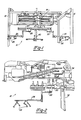
- FIGS. 1-4 The details of the combination transfer/turnover machine 10 are illustrated in FIGS. 1-4. Many of the details, such as pneumatic hose connections, mounting brackets and the like are self explanatory and therefore need not be described in this text in order for the person of ordinary skill in the art to understand the invention.
- the movement of carriage 12 is preferably provided by way of a drive mechanism that can be suspended between the two machines between which the parts are to be transferred by the apparatus 10.
- an electric chain drive 14 is employed.
- the chain drive 14, per se is of conventional design such as that provided by an ULTIMAX II dual motion programmable loader/unloader made by Clearing Mfg. Co. of Chicago, Illinois. Thus, the details of the chain drive 14 need not be discussed herein.
- the drive 14 includes electric motors under programmable control that drive suitable gearing arrangements cooperating with the chains to cause the desired vertical and/or horizontal movement of the carriage 12.
- the drive 14 is suspended between frames 16 and 18.
- the entire apparatus 10 be suspended from an overhead gantry as commonly found in a production factory as illustrated, for example, in FIG. 5.
- a horizontal bar 20 is connected to the carriage 12 and moves with it.
- a pair of transfer arms 22 and 24 are located on opposite lower ends of the bar 20. Means are provided on each transfer arm to pick up and carry the workpiece.
- each arm includes a plurality of fingers having vacuum suction cups 26 thereon for temporarily gripping the workpiece. As is known in the art, when vacuum is applied to cups 26, they operate to hold the part onto the arm so that it can be carried by it, and when the vacuum ceases, the part is released.
- Apparatus 10 advantageously includes a double-acting feature for each of the transfer arms 22 and 24.
- each of the arms can be moved along with the bar 20 and, in addition, they can move relative to the bar 20 under the control of actuators 28 and 30, respectively.
- the purpose of actuators 28 and 30 is to enable the arms 22 and 24 to be moved very quickly. As will appear, this will enable more efficient transfer of the parts between the two workstations.
- Various actuating designs may be employed.
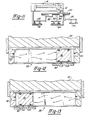
- FIGS. 12 and 13 illustrate an acceptable pneumatic design.
- air pressure selectively applied to ports 32 or 34 cause piston 36 to move to the right or left carrying with it bracket 38 connected to the transfer arm 22.
- the actuators may be driven by a ball/screw drive which is currently presently preferred.
- Transfer ber 20 also carries a turnover mechanism 40.
- Turnover mechanism 40 is connected to the lower portions of the bar 20 between the two arms 22 and 24.
- Turnover mechanism 40 is perhaps best shown in FIG. 4 as including a gripper 42 having a pair of gripping jaws 44, 46 which open and close about the workpiece in any suitable manner.
- the jaws operate in a scissors like action, each being pivoted at an intermediate point 48 under the control of the cylinder 50.
- Other suitable drive arrangements for the jaws can also be used such as a rack and pinion type mechanism.
- the gripping jaws are designed for a particular part configuration and can be easily replaced by another jaw design to accommodate differently shaped parts. In most other respects the machine 10 need not be modified even though the part changes.
- the gripper drive includes a vertically extending rack 52 having a wheel at one end serving as a cam follower 54.
- Rack 52 is suitably connected to the arm 20 via bracket 56 so that it moves horizontally with the bar 20.
- the cam follower 54 enters and follows a stationary cam track 58.
- cam track 58 includes a pair of open ended inclined rails 60 and 62 which are stationarily fixed via brackets to the chain drive 14.
- Apparatus 10 is shown as a one-piece unit that can be suspended from an electric bridge 72 that rides on the overhead beams 76 normally found in production factories.
- the apparatus 10 thus can be easily placed at desired locations in the factory, as well as being easily removed by energizing the bridge 72 to carry the apparatus along the beam 76 to the desired location. Removal may be necessary, for example, to provide access to the presses to change the dies therein or for other purposes.
- apparatus 10 is shown positioned between two metal stamping presses 78 and 80. Presses 78 and 80 operate in a predetermined sequence to perform sequential operations on a part.
- the presses 78, 80 and apparatus 10 are all suitably programmed to perform the following method.
- the press 78 is shown as just opening.
- the carriage 12 has moved transfer bar 20 to the left so that arm 22 is positioned as close as possible to the press 78 without interfering with its operation.
- Turnover mechanism 40 is located above a first deposit station 82 for temporarily holding a part.
- transfer arm 24 is positioned above a second deposit station 84.
- Deposit stations 82 and 84 are preferably platforms which are stationarily connected via struts 83, 85 to the housing of the chain drive 14 so that they also form a one-piece unit and nothing is permanently mounted on the floor of the factory.
- transfer bar 20 is moved upwardly and to the right towards the second press 80. As shown in FIG. 7, the horizontal movement of bar 20 causes the cam follower 52 to enter the mouth of the track 58 and begin in downward trek defined by the inclined rails of the track 58. This causes the rack 54 to move downwardly rotating pinion 64 and, thus, gripper 42.
- FIGS. 10-11 illustrate the substantially identical apparatus except that no provision is made to turn over the part during transfer between the presses. Instead, an intermediate transfer arm 90 is used. Transfer arm 90 is similar to transfer arms 22 and 24 but it does not include horizontal actuators. In all other respects the embodiment of FIGS. 10 and 11 is the same as the previously described embodiment. Various other modifications will become apparent to those skilled in the art after having the benefit of studying the specification, drawings and following claims.
Landscapes
- Engineering & Computer Science (AREA)
- Mechanical Engineering (AREA)
- Specific Conveyance Elements (AREA)
- Press Drives And Press Lines (AREA)
- Intermediate Stations On Conveyors (AREA)
Applications Claiming Priority (2)
| Application Number | Priority Date | Filing Date | Title |
|---|---|---|---|
| US245720 | 1988-09-16 | ||
| US07/245,720 US4921387A (en) | 1988-09-16 | 1988-09-16 | Combination transfer/turnover machine |
Publications (2)
| Publication Number | Publication Date |
|---|---|
| EP0358872A2 true EP0358872A2 (de) | 1990-03-21 |
| EP0358872A3 EP0358872A3 (de) | 1991-03-06 |
Family
ID=22927807
Family Applications (1)
| Application Number | Title | Priority Date | Filing Date |
|---|---|---|---|
| EP19890112366 Withdrawn EP0358872A3 (de) | 1988-09-16 | 1989-07-06 | Apparat und Verfahren zum Transportieren eines Werkstückes zwischen zwei Maschinen |
Country Status (2)
| Country | Link |
|---|---|
| US (1) | US4921387A (de) |
| EP (1) | EP0358872A3 (de) |
Cited By (3)
| Publication number | Priority date | Publication date | Assignee | Title |
|---|---|---|---|---|
| EP0659499A3 (de) * | 1993-12-21 | 1995-08-02 | Trantek Inc | |
| CN107570617A (zh) * | 2017-07-24 | 2018-01-12 | 深圳市嘉熠精密自动化科技有限公司 | 一种用于冲压机的自动下料装置 |
| CN114012020A (zh) * | 2021-10-18 | 2022-02-08 | 山东重诺锻造股份有限公司 | 一种翻坯机械手、油压机和法兰锻造翻坯方法 |
Families Citing this family (34)
| Publication number | Priority date | Publication date | Assignee | Title |
|---|---|---|---|---|
| SE464395B (sv) * | 1987-09-21 | 1991-04-22 | Volvo Ab | Hanteringsutrustning |
| US5006028A (en) * | 1990-05-18 | 1991-04-09 | Jackson Donald T | Cam lift and carry parts transfer apparatus |
| US5133444A (en) * | 1990-05-18 | 1992-07-28 | Juki America, Inc. | Method and apparatus for simultaneous transfer of workpieces between multiple stations |
| US5127787A (en) * | 1990-05-24 | 1992-07-07 | Brothers Industries, Inc. | Lift and carry mechanism and method |
| US5174709A (en) * | 1991-03-06 | 1992-12-29 | Leland D. Blatt | Workpiece transfer device |
| US5452981A (en) * | 1991-03-06 | 1995-09-26 | Leland D. Blatt | Automatic tool changer |
| DE19628333A1 (de) * | 1996-07-13 | 1998-01-15 | Schuler Pressen Gmbh & Co | Umsetzeinrichtung für Blechteile in einer Pressenanlage |
| US5738483A (en) * | 1996-09-11 | 1998-04-14 | Giddings & Lewis, Inc. | Lift and invert mechanism |
| SE515980C2 (sv) * | 1999-07-13 | 2001-11-05 | Binar Ab | En metod för snabb förflyttning av ett arbetsobjekt i både horisontalled och vertikalled från en arbetsstation till en annan |
| US6848566B2 (en) * | 2003-06-30 | 2005-02-01 | The Procter & Gamble Company | Continuously adjustable apparatus for repositioning discrete articles |
| DE102004006085B4 (de) * | 2004-02-07 | 2007-01-04 | Müller Weingarten AG | Transportvorrichtung für Werkstücke durch Pressenanlagen |
| AU2008204729B2 (en) * | 2007-01-12 | 2013-09-05 | Autobio Diagnostics Co., Ltd | Method and apparatus for orientating a solid growth culture medium plate |
| JP4935442B2 (ja) * | 2007-03-16 | 2012-05-23 | 村田機械株式会社 | 板材搬出装置および板材搬出方法 |
| US8100253B2 (en) | 2009-06-30 | 2012-01-24 | The Procter & Gamble Company | Methods and apparatuses for transferring discrete articles between carriers |
| US8607959B2 (en) | 2012-04-16 | 2013-12-17 | The Procter & Gamble Company | Rotational assemblies and methods for transferring discrete articles |
| US8720666B2 (en) | 2012-04-16 | 2014-05-13 | The Procter & Gamble Company | Apparatuses for transferring discrete articles |
| US8833542B2 (en) | 2012-04-16 | 2014-09-16 | The Procter & Gamble Company | Fluid systems and methods for transferring discrete articles |
| US8820513B2 (en) | 2012-04-16 | 2014-09-02 | The Procter & Gamble Company | Methods for transferring discrete articles |
| CN104736112A (zh) | 2012-10-23 | 2015-06-24 | 宝洁公司 | 用于将离散制品传送到纤维网上的方法 |
| US8667755B1 (en) * | 2013-03-14 | 2014-03-11 | Finfrock Industries, Inc. | Dual panel composite truss apparatus |
| US9463942B2 (en) | 2013-09-24 | 2016-10-11 | The Procter & Gamble Company | Apparatus for positioning an advancing web |
| US9527178B2 (en) * | 2014-04-16 | 2016-12-27 | Thermwood Corporation | Apparatus for inverting large panels |
| KR101494699B1 (ko) * | 2014-07-09 | 2015-02-26 | 이신영 | 제본 완성품의 적재장치 |
| US9511952B1 (en) | 2015-06-23 | 2016-12-06 | The Procter & Gamble Company | Methods for transferring discrete articles |
| US9511951B1 (en) | 2015-06-23 | 2016-12-06 | The Procter & Gamble Company | Methods for transferring discrete articles |
| US10717607B2 (en) | 2016-02-17 | 2020-07-21 | Wheelabrator Group, Inc. | Turnover mechanism of a conveyor system of a blast wheel machine |
| JP6823390B2 (ja) * | 2016-07-04 | 2021-02-03 | 川崎重工業株式会社 | ワークの反転装置 |
| US10322444B2 (en) * | 2017-01-17 | 2019-06-18 | Honda Motor Co., Ltd. | Apparatus, system, and method for manipulation of nested stamped parts |
| CN107946220A (zh) * | 2017-12-22 | 2018-04-20 | 君泰创新(北京)科技有限公司 | 电池片翻片装置 |
| IT202100000497A1 (it) * | 2021-01-13 | 2022-07-13 | Gmm S P A | Apparato e metodo per movimentare coppie di pezzi lavorati aventi una faccia grezza e una opposta faccia rifinita |
| US20240025665A1 (en) * | 2022-07-22 | 2024-01-25 | Manz Ag | Conveyor system with at least three axle devices |
| CN115945598B (zh) * | 2022-12-07 | 2026-05-01 | 惠州金源智能机器人有限公司 | 电池转向机构 |
| CN116532574B (zh) * | 2023-07-04 | 2023-09-19 | 合肥精亿工贸有限公司 | 一种用于汽车零部件的金属板冲压生产传输装置 |
| US12448222B2 (en) * | 2023-11-28 | 2025-10-21 | Oakwood Industries, LLC | Apparatus for manufacturing with overhead conveyor and pinch conveyor |
Family Cites Families (29)
| Publication number | Priority date | Publication date | Assignee | Title |
|---|---|---|---|---|
| US730424A (en) * | 1902-09-06 | 1903-06-09 | Fredrick E Wenzel | Labeling-machine. |
| US2259728A (en) * | 1939-07-26 | 1941-10-21 | Owens Illinois Glass Co | Apparatus for making hollow glass building blocks |
| US2332095A (en) * | 1940-04-29 | 1943-10-19 | Mcgibbon William | Apparatus for cleaning valves |
| US2904192A (en) * | 1956-11-23 | 1959-09-15 | Gen Electric | Lamp transfer apparatus |
| US3342125A (en) * | 1965-08-02 | 1967-09-19 | Danly Mach Specialties Inc | Apparatus for reversing a workpiece for an automatic press line |
| FR1571724A (de) * | 1967-06-30 | 1969-06-20 | ||
| US3468435A (en) * | 1968-04-18 | 1969-09-23 | Gleason Works | Transfer mechanism with work rotating device |
| US3651955A (en) * | 1970-06-29 | 1972-03-28 | Kaiser Aluminium Chem Corp | Workpiece handling and production apparatus |
| US3675302A (en) * | 1970-12-09 | 1972-07-11 | Paul H Dixon | Automatic assembly machine |
| GB1418852A (en) * | 1973-02-21 | 1975-12-24 | Schuler Gmbh L | Drives for automatic transfer mechanisms in press lines |
| FR2267199B1 (de) * | 1974-04-09 | 1982-10-15 | Schuler Gmbh L | |
| US3921822A (en) * | 1974-04-26 | 1975-11-25 | Dixon Babette | Machine for picking up, transferring and placing parts |
| AT348400B (de) * | 1974-10-15 | 1979-02-12 | Dyckerhoff & Widmann Ag | Vorrichtung zum herstellen von fertigteilen aus stahl- oder spannbeton |
| DE2544203C2 (de) * | 1975-10-03 | 1984-10-25 | L. Schuler GmbH, 7320 Göppingen | Wendevorrichtung |
| US4077523A (en) * | 1976-03-01 | 1978-03-07 | Gulf & Western Manufacturing Company | Vertically swinging article transfer apparatus |
| US4056198A (en) * | 1976-03-29 | 1977-11-01 | Danly Machine Corporation | Transfer and turnover mechanism for use with power press or the like |
| US4143776A (en) * | 1977-07-18 | 1979-03-13 | Mattison Machine Works | Apparatus for transferring and turning over parts |
| GB2006077B (en) * | 1977-10-21 | 1982-01-13 | Schuler Gmbh L | Workpiece conveyor device |
| JPS5473376A (en) * | 1977-11-24 | 1979-06-12 | Toyoda Mach Works Ltd | In-line type work transportation machine |
| FR2529809B2 (fr) * | 1979-09-21 | 1986-05-30 | Citroen Sa | Chargeur ou extracteur de pieces |
| US4386693A (en) * | 1981-04-23 | 1983-06-07 | The Budd Company | Transfer apparatus |
| NL8102620A (nl) * | 1981-05-29 | 1982-12-16 | Philips Nv | Werkwijze voor de vervaardiging van gedrukte bedrading en aldus verkregen produkten. |
| DE3301449A1 (de) * | 1982-01-29 | 1983-09-15 | Honda Giken Kogyo K.K., Tokyo | Schweissvorrichtung fuer fahrzeugkoerper zweiraedriger fahrzeuge |
| US4643634A (en) * | 1983-08-12 | 1987-02-17 | F. J. Littell Machine Co. | Work piece transporting apparatus |
| US4547115A (en) * | 1984-01-25 | 1985-10-15 | Charbonnet Carl D | Apparatus for transporting and aligning panel-like members |
| US4697231A (en) * | 1985-06-21 | 1987-09-29 | F. J. Littell Machine Company | Machine control system |
| IT1182515B (it) * | 1985-07-15 | 1987-10-05 | Imp Prima Spa | Dispositivo manipolatore particolarmente per il maneggio di lamiere durante operazioni di piegatura |
| JPS6221434A (ja) * | 1985-07-19 | 1987-01-29 | Toyota Motor Corp | プレス機へのワ−ク搬出入装置 |
| US4727976A (en) * | 1986-08-11 | 1988-03-01 | Toyota Jidosha Kabushiki Kaisha | Workpiece conveyor |
-
1988
- 1988-09-16 US US07/245,720 patent/US4921387A/en not_active Expired - Fee Related
-
1989
- 1989-07-06 EP EP19890112366 patent/EP0358872A3/de not_active Withdrawn
Cited By (4)
| Publication number | Priority date | Publication date | Assignee | Title |
|---|---|---|---|---|
| EP0659499A3 (de) * | 1993-12-21 | 1995-08-02 | Trantek Inc | |
| CN107570617A (zh) * | 2017-07-24 | 2018-01-12 | 深圳市嘉熠精密自动化科技有限公司 | 一种用于冲压机的自动下料装置 |
| CN114012020A (zh) * | 2021-10-18 | 2022-02-08 | 山东重诺锻造股份有限公司 | 一种翻坯机械手、油压机和法兰锻造翻坯方法 |
| CN114012020B (zh) * | 2021-10-18 | 2023-09-26 | 山东重诺锻造股份有限公司 | 一种翻坯机械手、油压机和法兰锻造翻坯方法 |
Also Published As
| Publication number | Publication date |
|---|---|
| EP0358872A3 (de) | 1991-03-06 |
| US4921387A (en) | 1990-05-01 |
Similar Documents
| Publication | Publication Date | Title |
|---|---|---|
| US4921387A (en) | Combination transfer/turnover machine | |
| EP0262132B1 (de) | Vorrichtung zum automatischen laden einer palette | |
| US5141093A (en) | Automotive body panel handling apparatus | |
| US8348590B2 (en) | Device for treating and/or handling articles | |
| US4678393A (en) | Loading and unloading mechanism | |
| US5326201A (en) | Loader/unloader for blind broaching | |
| US2934218A (en) | Automatic device for transferring workpieces from one machine-tool to another | |
| GB2052436A (en) | Labelling apparatus | |
| CN118617162B (zh) | 一种用于待加工轴套的自动定位系统 | |
| JPS6054235A (ja) | 被加工物の自動送り装置 | |
| JPH0666982U (ja) | 板材把持装置 | |
| US4690050A (en) | Transfer system for article printing machine | |
| US4491451A (en) | Work handling assembly for depositing a workpiece into the die space of a drop-forging press | |
| EP0123478B1 (de) | Einrichtung zum Fördern von Werkstücken | |
| JPS63500027A (ja) | 部品搬送用載荷および荷卸しシステム | |
| CN118083647A (zh) | 一种卷接机组自动供纸设备 | |
| JPH09388U (ja) | 板材把持装置 | |
| CN211870709U (zh) | 上下料结构及系统 | |
| JPH09206822A (ja) | 押出機用金型のピッキング装置 | |
| CN220074699U (zh) | 一种铝材定位摆杆机械手 | |
| JP2924700B2 (ja) | 製品切り離し装置 | |
| US3659693A (en) | Loading device for processing machines | |
| EP3398712A1 (de) | System und verfahren zum entladen von teilen | |
| JPS629730A (ja) | 空気制御式トランスフア−ユニツト | |
| RU2118274C1 (ru) | Машина для укладки штучных изделий в тару |
Legal Events
| Date | Code | Title | Description |
|---|---|---|---|
| PUAI | Public reference made under article 153(3) epc to a published international application that has entered the european phase |
Free format text: ORIGINAL CODE: 0009012 |
|
| AK | Designated contracting states |
Kind code of ref document: A2 Designated state(s): DE FR GB IT NL SE |
|
| PUAL | Search report despatched |
Free format text: ORIGINAL CODE: 0009013 |
|
| AK | Designated contracting states |
Kind code of ref document: A3 Designated state(s): DE FR GB IT NL SE |
|
| 17P | Request for examination filed |
Effective date: 19910430 |
|
| 17Q | First examination report despatched |
Effective date: 19920217 |
|
| STAA | Information on the status of an ep patent application or granted ep patent |
Free format text: STATUS: THE APPLICATION HAS BEEN WITHDRAWN |
|
| 18W | Application withdrawn |
Withdrawal date: 19930118 |