EP0358894B1 - Dispositif de présélection et de changement de vitesse pour une boîte de vitesses pour automobiles - Google Patents
Dispositif de présélection et de changement de vitesse pour une boîte de vitesses pour automobiles Download PDFInfo
- Publication number
- EP0358894B1 EP0358894B1 EP89113529A EP89113529A EP0358894B1 EP 0358894 B1 EP0358894 B1 EP 0358894B1 EP 89113529 A EP89113529 A EP 89113529A EP 89113529 A EP89113529 A EP 89113529A EP 0358894 B1 EP0358894 B1 EP 0358894B1
- Authority
- EP
- European Patent Office
- Prior art keywords
- gearstick
- rocker arms
- gear shift
- shift lever
- shift
- Prior art date
- Legal status (The legal status is an assumption and is not a legal conclusion. Google has not performed a legal analysis and makes no representation as to the accuracy of the status listed.)
- Expired - Lifetime
Links
Images


Classifications
-
- F—MECHANICAL ENGINEERING; LIGHTING; HEATING; WEAPONS; BLASTING
- F16—ENGINEERING ELEMENTS AND UNITS; GENERAL MEASURES FOR PRODUCING AND MAINTAINING EFFECTIVE FUNCTIONING OF MACHINES OR INSTALLATIONS; THERMAL INSULATION IN GENERAL
- F16H—GEARING
- F16H59/00—Control inputs to control units of change-speed- or reversing-gearings for conveying rotary motion
- F16H59/02—Selector apparatus
- F16H59/04—Ratio selector apparatus
- F16H59/042—Ratio selector apparatus comprising a final actuating mechanism
-
- B—PERFORMING OPERATIONS; TRANSPORTING
- B60—VEHICLES IN GENERAL
- B60K—ARRANGEMENT OR MOUNTING OF PROPULSION UNITS OR OF TRANSMISSIONS IN VEHICLES; ARRANGEMENT OR MOUNTING OF PLURAL DIVERSE PRIME-MOVERS IN VEHICLES; AUXILIARY DRIVES FOR VEHICLES; INSTRUMENTATION OR DASHBOARDS FOR VEHICLES; ARRANGEMENTS IN CONNECTION WITH COOLING, AIR INTAKE, GAS EXHAUST OR FUEL SUPPLY OF PROPULSION UNITS IN VEHICLES
- B60K20/00—Arrangement or mounting of change-speed gearing control devices in vehicles
- B60K20/02—Arrangement or mounting of change-speed gearing control devices in vehicles of initiating means
-
- F—MECHANICAL ENGINEERING; LIGHTING; HEATING; WEAPONS; BLASTING
- F16—ENGINEERING ELEMENTS AND UNITS; GENERAL MEASURES FOR PRODUCING AND MAINTAINING EFFECTIVE FUNCTIONING OF MACHINES OR INSTALLATIONS; THERMAL INSULATION IN GENERAL
- F16H—GEARING
- F16H59/00—Control inputs to control units of change-speed- or reversing-gearings for conveying rotary motion
- F16H59/02—Selector apparatus
- F16H2059/026—Details or special features of the selector casing or lever support
- F16H2059/0265—Selector lever support with pivot axis offset, e.g. support by four bar linkage to create pivoting centre outside the mechanism
-
- Y—GENERAL TAGGING OF NEW TECHNOLOGICAL DEVELOPMENTS; GENERAL TAGGING OF CROSS-SECTIONAL TECHNOLOGIES SPANNING OVER SEVERAL SECTIONS OF THE IPC; TECHNICAL SUBJECTS COVERED BY FORMER USPC CROSS-REFERENCE ART COLLECTIONS [XRACs] AND DIGESTS
- Y10—TECHNICAL SUBJECTS COVERED BY FORMER USPC
- Y10T—TECHNICAL SUBJECTS COVERED BY FORMER US CLASSIFICATION
- Y10T74/00—Machine element or mechanism
- Y10T74/20—Control lever and linkage systems
- Y10T74/20012—Multiple controlled elements
- Y10T74/20018—Transmission control
-
- Y—GENERAL TAGGING OF NEW TECHNOLOGICAL DEVELOPMENTS; GENERAL TAGGING OF CROSS-SECTIONAL TECHNOLOGIES SPANNING OVER SEVERAL SECTIONS OF THE IPC; TECHNICAL SUBJECTS COVERED BY FORMER USPC CROSS-REFERENCE ART COLLECTIONS [XRACs] AND DIGESTS
- Y10—TECHNICAL SUBJECTS COVERED BY FORMER USPC
- Y10T—TECHNICAL SUBJECTS COVERED BY FORMER US CLASSIFICATION
- Y10T74/00—Machine element or mechanism
- Y10T74/20—Control lever and linkage systems
- Y10T74/20396—Hand operated
Definitions
- the invention relates to a device for preselecting and shifting a motor vehicle gear shift transmission according to the preamble of claim 1.
- a similar gear shifting device is described in DE-OS 27 43 875.
- the shift lever is guided on a four-bar linkage, which is composed of two mutually parallel rockers and a shift lever housing forming the coupling.
- the gear lever is pivotally mounted in the gear lever housing by means of a ball joint.
- a special arrangement of the articulated axes and coordination of the center distances is intended to ensure that oscillating movements of the transmission are not transferred to corresponding movements on the shift lever. In particular, no forward, backward or vertical movements of the button of the shift lever to be actuated by the driver should occur so as not to irritate the driver and to keep the button at rest.
- a crosspiece of the shift lever is the coupling of the four-bar linkage or is rigidly connected to it, appropriate dimensioning of the lengths and distances of the articulation points of the rockers allows an approximate straight line of the shift lever handle and the achieve shift rod attached to the shift lever.
- a pivot pin which is fastened in both eyes and projects from them serves as the crosspiece of the shift lever. On it left and right joint parts are mounted, on which the wings are hinged. If the shift lever is pivoted about the pivot pin, the shift rod is rotated about its longitudinal axis in order to preselect the transmission gears.
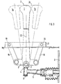
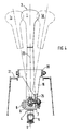
- a shift lever 1 of a motor vehicle gear shift transmission 2 is provided at its upper end with a handle 3 to be operated by the driver. At its lower end, the shift lever 1 is connected via a joint piece 4 to a shift rod 5 engaging in the gear shift transmission 2.
- the hinge piece 4 is formed by two U-shaped tabs 6 and 7, which engage around the shift lever, which are articulated on the shift rod 5 via a hinge pin 8 and a pin 9, which is perpendicular to the hinge pin 8 and to which the shift rod 5 is rotatably connected .
- a cross piece 1 ' is attached to the shift lever 1, which forms the coupling of the four-bar linkage.
- the cross piece 1 'of the shift lever 1 consists of eyes 10, 11 on both sides, in whose bores a pivot pin 12 is fastened.
- Joint parts 13, 14 are attached to the ends of the joint pin 12 protruding from the eyes 10, 11 and axially secured by split pins.
- a shorter rocker arm 15 is articulated on the left joint part 13, and a longer rocker arm 16 is articulated with the pins 17 and 18 on the right joint part 14.
- the two rockers 15 and 16 are articulated in fixed bearing points 19, 20 of a frame part 21 of the motor vehicle with screw pins so that the longitudinal center lines of the rockers form an acute angle to one another and that they intersect near the longitudinal central axis 22 of the shift lever 1.
- the two rockers 15, 16, the fixed bearing points 19, 20 and the two joint parts 13, 14 with the pins 17, 18 form a four-bar linkage, the coupling of which represents the eyes 10, 11 of the shift lever 1 and the pivot pin 12 fastened in them.
- the four-bar linkage is supplemented to a spatial four-bar linkage for better storage stability, in that a further shorter link 15a is attached parallel to the shorter link 15 the fixed bearing 19 is articulated; the same applies to the longer rocker arm 16.
- the frame part 21 can be slidably screwed to the chassis 23 in order to be able to change the basic position of the shift lever 1 relative to the shift rod 5.
- the shift lever 1 moves into either the left shift position 1a or the right shift position 1b.
- the four-bar linkage is dimensioned such that the highest point of the handle 3 moves on an approximate straight line 24.
- a ball joint 25 can replace the joint parts 13, 14.
- the rocker arms 15, 16 must be arranged and their lengths selected so that the pivot axis of the shift lever for preselecting the transmission gears lies on the pivot axes of the rocker arms 15, 16 on the shift lever 1.
- the left rocker 15 and right rocker 16 have the same length here. Adequate storage stability can already be achieved by two rockers 15, 16.
- the wings 15, 16 are rotatable at fixed bearing points 19, 20 of the frame part 21, below they are articulated with ball joints 25 to the cross piece 1 formed on the shift lever 1 '.
- a joint piece 4 is also rotatably connected to the shift lever 1, via which the movements of the shift lever are transmitted to the shift rod 5.
- the translation of the switching and preselection paths of the shift rod 5 to the pivoting movements of the shift lever can be determined by choosing the articulation points of the four-bar linkage and by dimensioning the length of its wings 15, 16.
- the uppermost point of the grip piece can execute any curved curve with a different design of the quadrilateral joint, if the shift lever is easier to handle for the driver of the motor vehicle with such a course of movement.
Landscapes
- Engineering & Computer Science (AREA)
- Mechanical Engineering (AREA)
- General Engineering & Computer Science (AREA)
- Chemical & Material Sciences (AREA)
- Combustion & Propulsion (AREA)
- Transportation (AREA)
- Arrangement Or Mounting Of Control Devices For Change-Speed Gearing (AREA)
- Gear-Shifting Mechanisms (AREA)
- Control Of Transmission Device (AREA)
Claims (7)
- Dispositif de présélection et de changement de vitesse pour une boîte de vitesses (2) d'un véhicule automobile comportant un levier de manoeuvre (1), qui à son extrémité supérieure est pourvu d'une poignée (3) et qui dans la zone de l'extrémité inférieure est guidé par un carré d'articulation (4), qui est constitué d'au moins deux bras oscillants (15, 16) montés pivotants sur le châssis du véhicule et d'une bielle les reliant de manière articulée, une tige de manoeuvre (5), s'engageant dans la boîte de vitesses (2), étant articulée à l'extrémité inférieure du levier de manoeuvre (1) caractérisé en ce qu'une pièce transversale (1') du levier de manoeuvre (1) forme la bielle du carré d'articulation et en ce que sur ses deux côtés s'articulent les bras oscillants (15, 16).
- Dispositif selon la revendication 1, caractérisé en ce que les bras oscillants (15, 16) s'étendent l'un vers l'autre en formant un angle aigu et en ce que leurs lignes médianes longitudinales se coupent à proximité de la ligne médiane longitudinale (22) du levier de manoeuvre (1).
- Dispositif selon les revendications 1 ou 2, caractérisé en ce que sur les deux côtés longitudinaux du levier de manoeuvre (1) s'articulent deux bras oscillants (15, 15a) gauches et bras oscillants droits (16, 16a) parallèles entre eux.
- Dispositif selon les revendications 1 et 2, caractérisé en ce que les bras oscillants (15, 16) s'articulent sur une partie d'articulation gauche (13) et une partie d'articulation droite (14) et en ce que les parties d'articulation (13, 14) sont reliées par un pivot d'articulation (12) traversant, de manière à pouvoir tourner avec le levier de manoeuvre (1)
- Dispositif selon les revendications 1 et 2, caractérisé en ce que les deux bras oscillants (15, 16) s'articulent sur le levier de manoeuvre (1), chacun avec un joint sphérique (22).
- Dispositif selon l'une des revendications 1 à 5, caractérisé en ce que sur le levier de manoeuvre (1) , au-dessous des points d'articulation des bras oscillants (15, 16), s'articule une pièce d'articulation (4) sur laquelle est fixée tournante la tige de manoeuvre (5) menant à la boîte de vitesses (2).
- Dispositif selon la revendication 1, caractérisé en ce que le point d'articulation (19, 20) des bras oscillants (15, 16) sur le châssis (23) du véhicule est fixé de manière réglable par rapport à celui-ci.
Applications Claiming Priority (2)
| Application Number | Priority Date | Filing Date | Title |
|---|---|---|---|
| DE3831310A DE3831310A1 (de) | 1988-09-15 | 1988-09-15 | Vorrichtung zum vorwaehlen und schalten eines kraftfahrzeug-gangschaltgetriebes |
| DE3831310 | 1988-09-15 |
Publications (3)
| Publication Number | Publication Date |
|---|---|
| EP0358894A2 EP0358894A2 (fr) | 1990-03-21 |
| EP0358894A3 EP0358894A3 (fr) | 1991-06-12 |
| EP0358894B1 true EP0358894B1 (fr) | 1993-11-18 |
Family
ID=6362966
Family Applications (1)
| Application Number | Title | Priority Date | Filing Date |
|---|---|---|---|
| EP89113529A Expired - Lifetime EP0358894B1 (fr) | 1988-09-15 | 1989-07-22 | Dispositif de présélection et de changement de vitesse pour une boîte de vitesses pour automobiles |
Country Status (5)
| Country | Link |
|---|---|
| US (1) | US5022281A (fr) |
| EP (1) | EP0358894B1 (fr) |
| JP (1) | JPH02109736A (fr) |
| DE (2) | DE3831310A1 (fr) |
| ES (1) | ES2046391T3 (fr) |
Families Citing this family (8)
| Publication number | Priority date | Publication date | Assignee | Title |
|---|---|---|---|---|
| US5182961A (en) * | 1991-07-30 | 1993-02-02 | Honeywell Inc. | Three degree of freedom translational axis hand controller mechanism |
| FR2734214B1 (fr) * | 1995-05-17 | 1997-07-04 | Renault | Dispositif de commande d'une boite de vitesses muni d'un bati deporte |
| SE517453C2 (sv) * | 1997-06-27 | 2002-06-11 | Kongsberg Automotive Ab | Manöveranordning |
| SE511147C2 (sv) * | 1997-12-19 | 1999-08-09 | Kongsberg Automotive Ab | Manöveranordning |
| SE512418C2 (sv) | 1998-06-29 | 2000-03-13 | Kongsberg Automotive Ab | Manöveranordning |
| DE10060803A1 (de) * | 2000-12-07 | 2002-07-04 | Deere & Co | Schaltvorrichtung für ein Fahrzeuggetriebe |
| JP4236515B2 (ja) * | 2003-05-26 | 2009-03-11 | 小島プレス工業株式会社 | シフトレバー装置 |
| DE102006039860B3 (de) * | 2006-08-25 | 2008-03-27 | Zf Friedrichshafen Ag | Betätigungsvorrichtung für Kraftfahrzeuggetriebe |
Family Cites Families (6)
| Publication number | Priority date | Publication date | Assignee | Title |
|---|---|---|---|---|
| GB1402662A (en) * | 1973-01-18 | 1975-08-13 | Chrysler Uk | Gear change mechanisms |
| JPS51141957A (en) * | 1975-05-30 | 1976-12-07 | Toyota Motor Corp | Operating device of change gear for automobile |
| US4132124A (en) * | 1976-09-29 | 1979-01-02 | Manno Kogyo Company, Limited | Shift mechanism for automotive transmission |
| JPS5632335Y2 (fr) * | 1976-10-30 | 1981-08-01 | ||
| US4625842A (en) * | 1985-06-03 | 1986-12-02 | Deere & Company | U-pattern hydrostatic transmission control linkage |
| JPS628210A (ja) * | 1985-07-04 | 1987-01-16 | Keihin Seimitsu Kogyo Kk | 可動型シフトレバ−装置 |
-
1988
- 1988-09-15 DE DE3831310A patent/DE3831310A1/de not_active Withdrawn
-
1989
- 1989-07-22 ES ES198989113529T patent/ES2046391T3/es not_active Expired - Lifetime
- 1989-07-22 DE DE89113529T patent/DE58906198D1/de not_active Expired - Fee Related
- 1989-07-22 EP EP89113529A patent/EP0358894B1/fr not_active Expired - Lifetime
- 1989-09-12 JP JP1234832A patent/JPH02109736A/ja active Pending
- 1989-09-15 US US07/408,112 patent/US5022281A/en not_active Expired - Fee Related
Also Published As
| Publication number | Publication date |
|---|---|
| DE3831310A1 (de) | 1990-03-29 |
| US5022281A (en) | 1991-06-11 |
| ES2046391T3 (es) | 1994-02-01 |
| JPH02109736A (ja) | 1990-04-23 |
| DE58906198D1 (de) | 1993-12-23 |
| EP0358894A2 (fr) | 1990-03-21 |
| EP0358894A3 (fr) | 1991-06-12 |
Similar Documents
| Publication | Publication Date | Title |
|---|---|---|
| DE69801325T2 (de) | Verbesserte gelenkvorrichtung eines an einer kraftfahrzeugkarosserie schwenkbar angeordneten flügels | |
| EP0358894B1 (fr) | Dispositif de présélection et de changement de vitesse pour une boîte de vitesses pour automobiles | |
| DE3734814C2 (fr) | ||
| DE102005001818B4 (de) | Schaltvorrichtung für ein Automatikgetriebe eines Kraftfahrzeuges | |
| DE2747189A1 (de) | Verstellmechanismus fuer einen fahrzeugsitz | |
| DE4238070C2 (de) | Hebelbetätigungsvorrichtung für einen Schalter | |
| DE10219477C1 (de) | Mehrwegeschaltmittel | |
| DE69014253T2 (de) | Scheinwerfereinrichtung für Fahrzeuge. | |
| DE68919855T2 (de) | Gelenkfahrzeug mit lenkgestänge. | |
| DE3115606C2 (de) | Lenk- und Antriebseinrichtung | |
| DE19737036B4 (de) | Lenkmodul eines Kraftfahrzeugs mit sowohl in ihrer Neigung als auch in der Länge verstellbarer Lenksäule | |
| DE3428703C2 (de) | Vorrichtung zur Höhenverstellung von Sitzen, insbesondere Kraftfahrzeugsitzen | |
| DE4446741B4 (de) | Betätigungseinrichtung | |
| DE3618673A1 (de) | Fahrzeugsitz mit einer schenkelstuetze | |
| EP0736444B1 (fr) | Timon pour un chariot de manutention | |
| DE102006042202B4 (de) | Verdeckantrieb | |
| DE2731332C2 (de) | Schwenkvorrichtung für Fahrzeugscheinwerfer | |
| DE19645343B4 (de) | Radaufhängung für ein lenkbares Fahrzeugrad | |
| DE2616239A1 (de) | Gelenkfensterheber, insbesondere fuer kraftfahrzeuge | |
| DE3319958C2 (de) | Lenksystem für ein lenkbare Vorder- und Hinterräder aufweisendes Fahrzeug | |
| DE3014067C2 (de) | Fernschaltvorrichtung für das Gangwechselgetriebe eines Kraftfahrzeuges | |
| DE29615268U1 (de) | Weiche | |
| DE29702964U1 (de) | Getriebeschalteinrichtung | |
| DE102004030724B4 (de) | Schaltvorrichtung für ein Getriebe eines Kraftfahrzeugs, insbesondere Frontlenker- Lastkraftwagens | |
| DE102005047192B3 (de) | Verstellbares Fahrzeugdach |
Legal Events
| Date | Code | Title | Description |
|---|---|---|---|
| PUAI | Public reference made under article 153(3) epc to a published international application that has entered the european phase |
Free format text: ORIGINAL CODE: 0009012 |
|
| AK | Designated contracting states |
Kind code of ref document: A2 Designated state(s): DE ES FR GB IT SE |
|
| PUAL | Search report despatched |
Free format text: ORIGINAL CODE: 0009013 |
|
| RHK1 | Main classification (correction) |
Ipc: F16H 59/04 |
|
| AK | Designated contracting states |
Kind code of ref document: A3 Designated state(s): DE ES FR GB IT SE |
|
| 17P | Request for examination filed |
Effective date: 19911108 |
|
| 17Q | First examination report despatched |
Effective date: 19930330 |
|
| ITF | It: translation for a ep patent filed | ||
| GRAA | (expected) grant |
Free format text: ORIGINAL CODE: 0009210 |
|
| AK | Designated contracting states |
Kind code of ref document: B1 Designated state(s): DE ES FR GB IT SE |
|
| REF | Corresponds to: |
Ref document number: 58906198 Country of ref document: DE Date of ref document: 19931223 |
|
| ET | Fr: translation filed | ||
| REG | Reference to a national code |
Ref country code: ES Ref legal event code: FG2A Ref document number: 2046391 Country of ref document: ES Kind code of ref document: T3 |
|
| GBT | Gb: translation of ep patent filed (gb section 77(6)(a)/1977) |
Effective date: 19940113 |
|
| PG25 | Lapsed in a contracting state [announced via postgrant information from national office to epo] |
Ref country code: GB Effective date: 19940722 |
|
| PG25 | Lapsed in a contracting state [announced via postgrant information from national office to epo] |
Ref country code: SE Effective date: 19940723 Ref country code: ES Free format text: LAPSE BECAUSE OF THE APPLICANT RENOUNCES Effective date: 19940723 |
|
| PLBE | No opposition filed within time limit |
Free format text: ORIGINAL CODE: 0009261 |
|
| STAA | Information on the status of an ep patent application or granted ep patent |
Free format text: STATUS: NO OPPOSITION FILED WITHIN TIME LIMIT |
|
| 26N | No opposition filed | ||
| EUG | Se: european patent has lapsed |
Ref document number: 89113529.5 Effective date: 19950210 |
|
| GBPC | Gb: european patent ceased through non-payment of renewal fee |
Effective date: 19940722 |
|
| PG25 | Lapsed in a contracting state [announced via postgrant information from national office to epo] |
Ref country code: FR Effective date: 19950331 |
|
| PG25 | Lapsed in a contracting state [announced via postgrant information from national office to epo] |
Ref country code: DE Effective date: 19950401 |
|
| EUG | Se: european patent has lapsed |
Ref document number: 89113529.5 |
|
| REG | Reference to a national code |
Ref country code: FR Ref legal event code: ST |
|
| REG | Reference to a national code |
Ref country code: ES Ref legal event code: FD2A Effective date: 20001009 |
|
| PG25 | Lapsed in a contracting state [announced via postgrant information from national office to epo] |
Ref country code: IT Free format text: LAPSE BECAUSE OF NON-PAYMENT OF DUE FEES;WARNING: LAPSES OF ITALIAN PATENTS WITH EFFECTIVE DATE BEFORE 2007 MAY HAVE OCCURRED AT ANY TIME BEFORE 2007. THE CORRECT EFFECTIVE DATE MAY BE DIFFERENT FROM THE ONE RECORDED. Effective date: 20050722 |